


 En
En


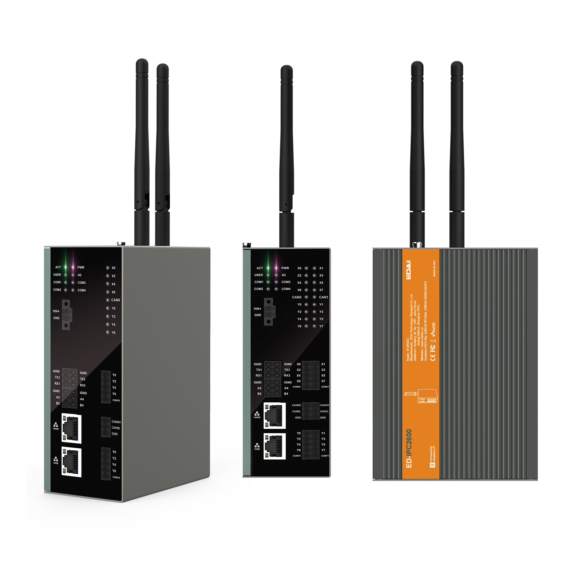


| Model No. | CAN | DI | DO |
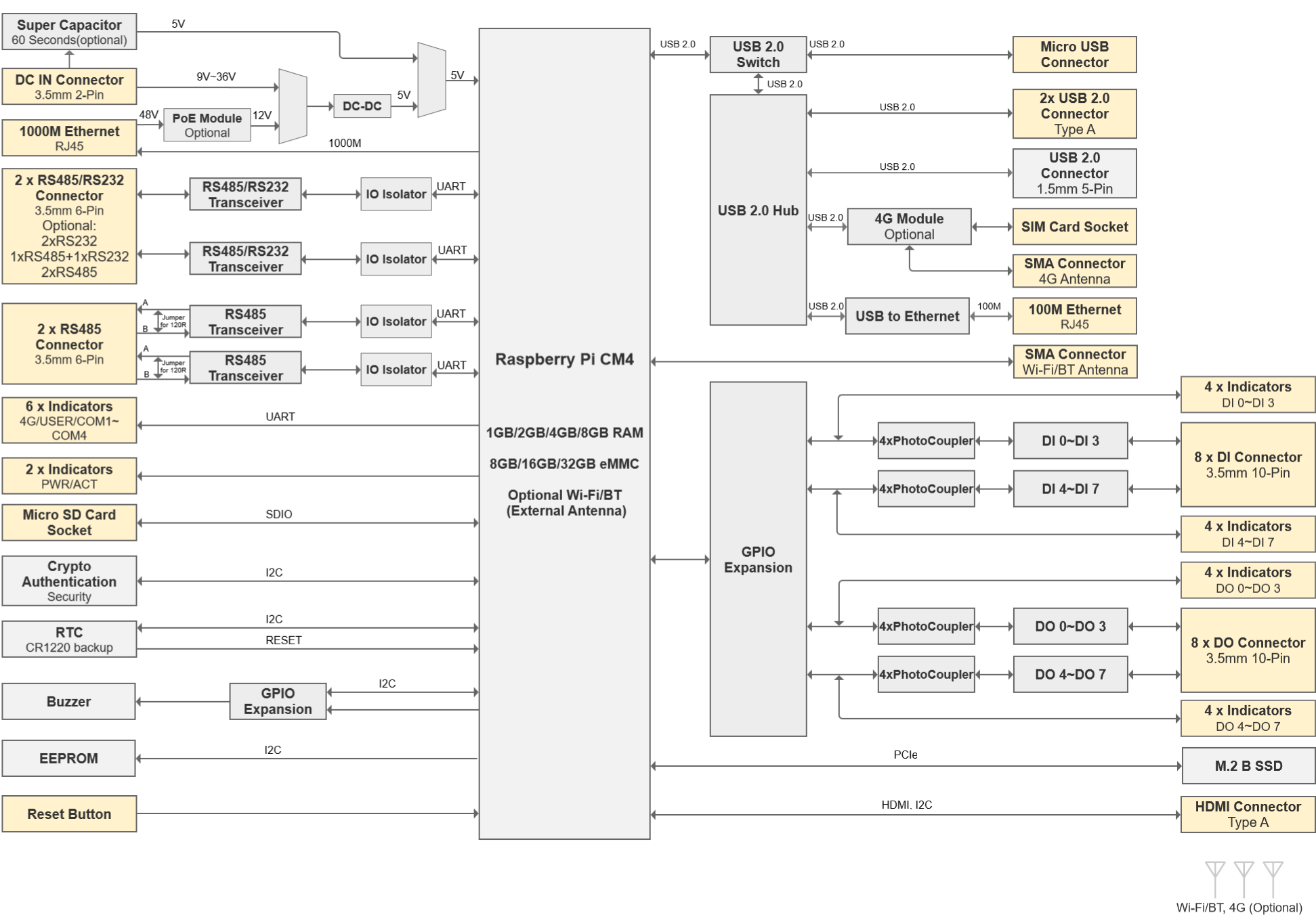
| IPC2610 | - | x 8 | x 8 |
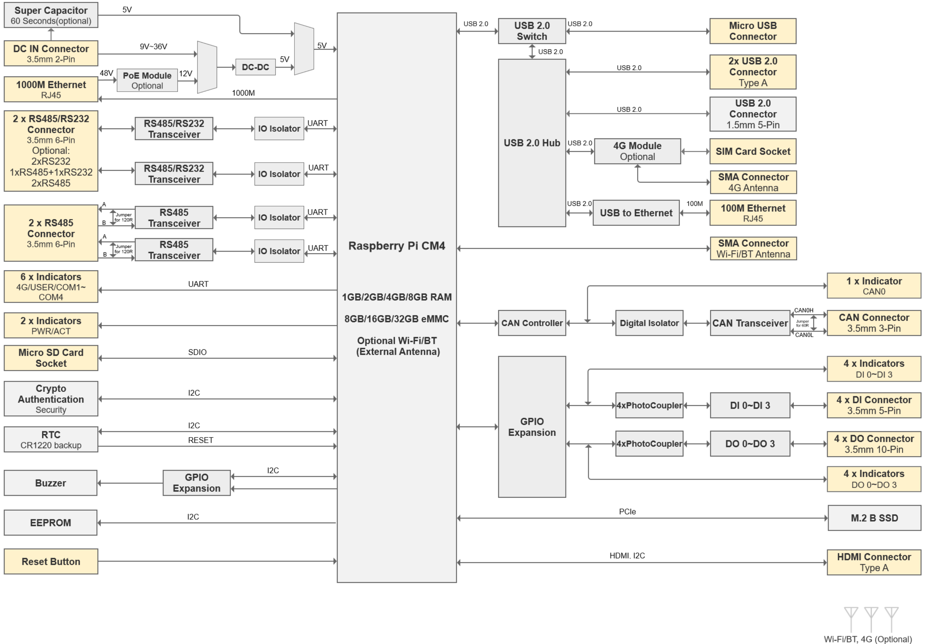
| IPC2620 | x 1 | x 4 | x 4 |
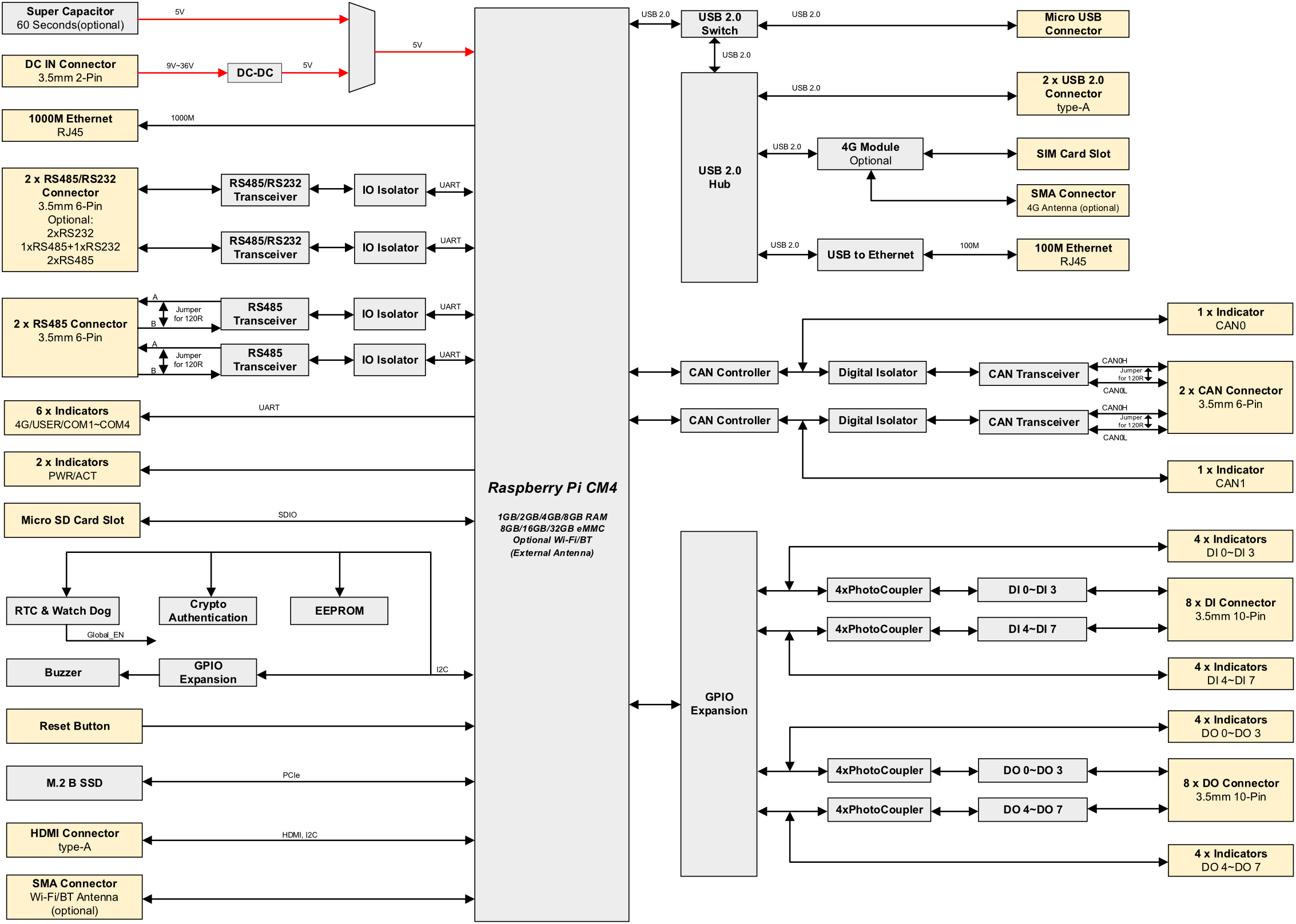
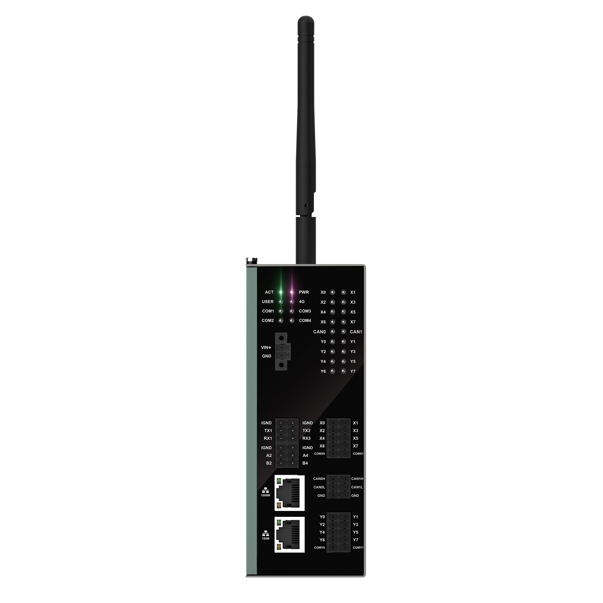
| IPC2630 | x 2 | x 8 | x 8 |

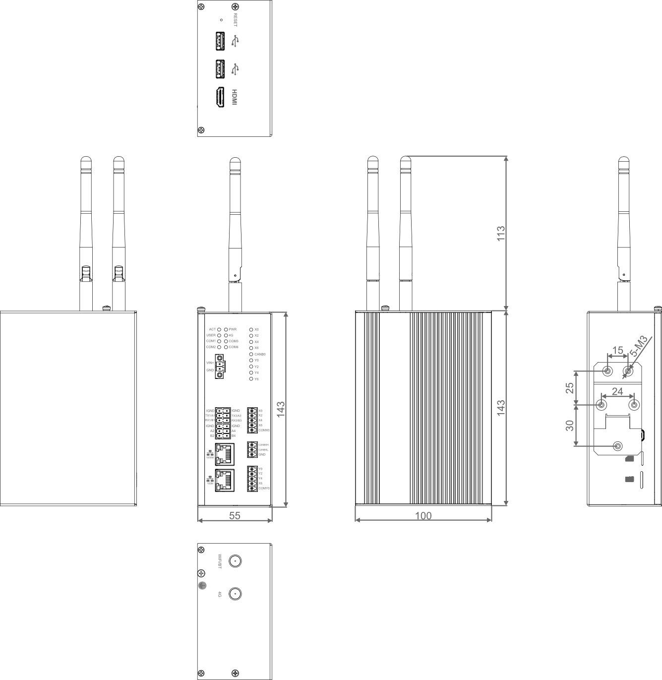
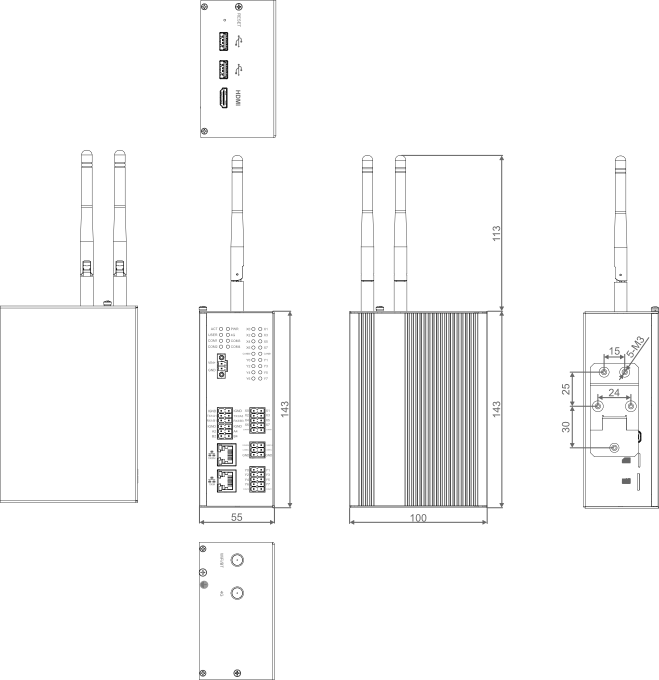
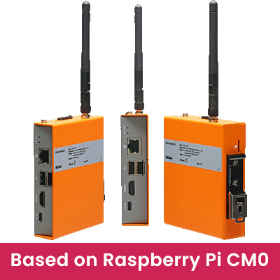
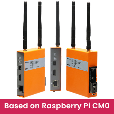
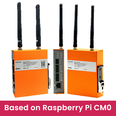
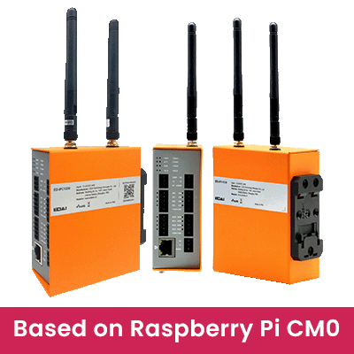
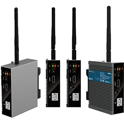
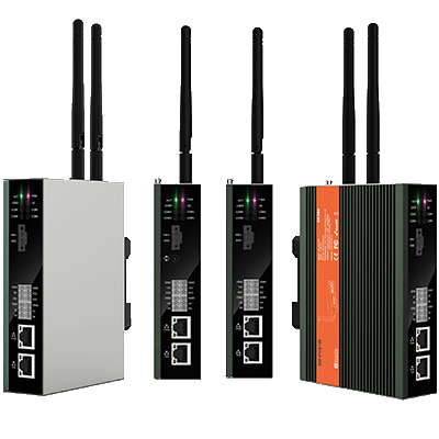
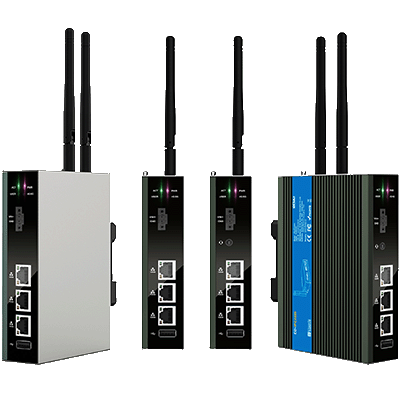
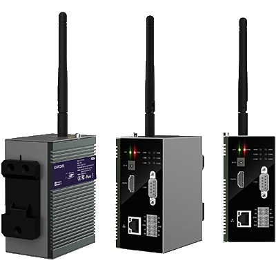
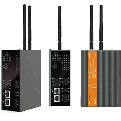
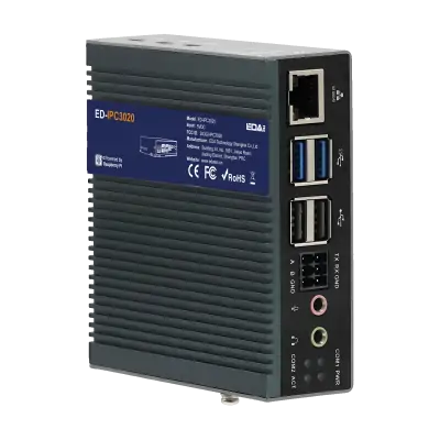
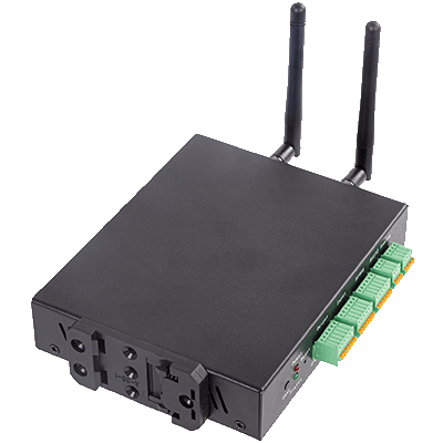
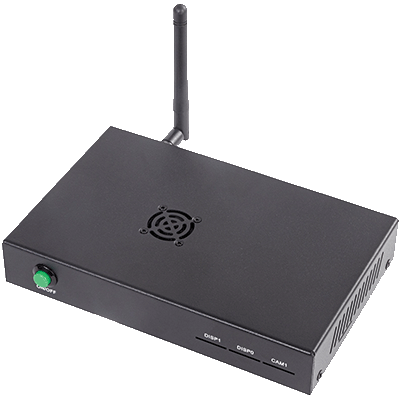
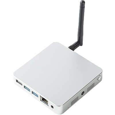
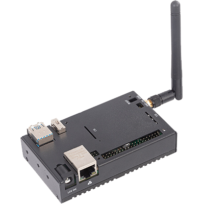
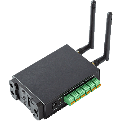
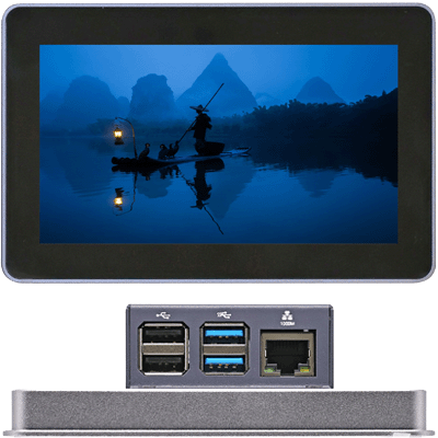
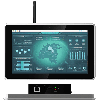
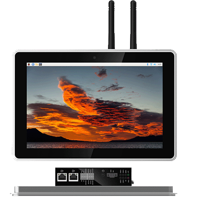
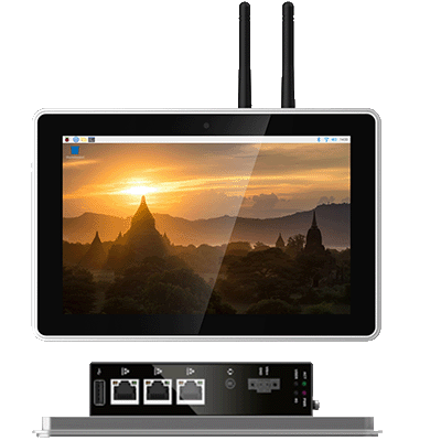
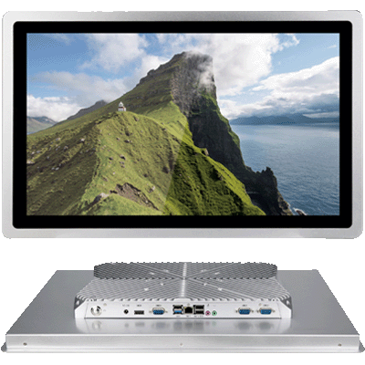
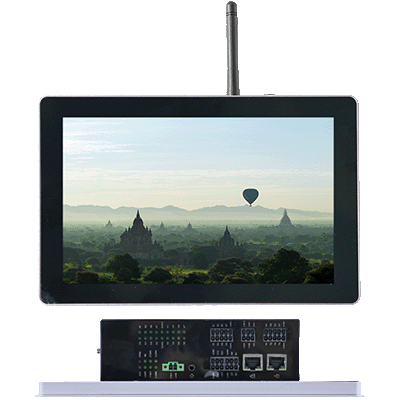
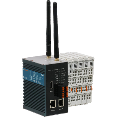
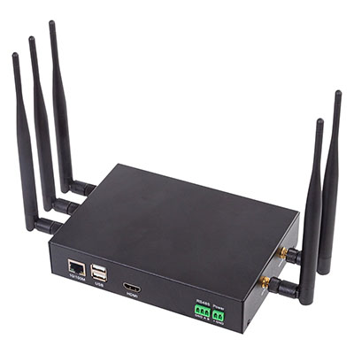
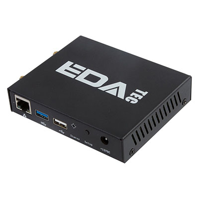
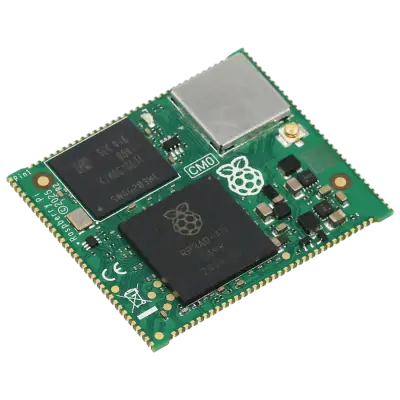
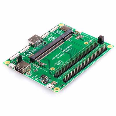
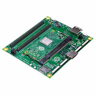
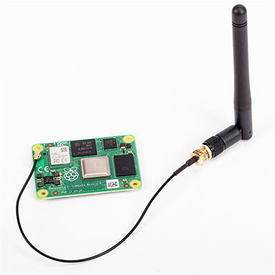
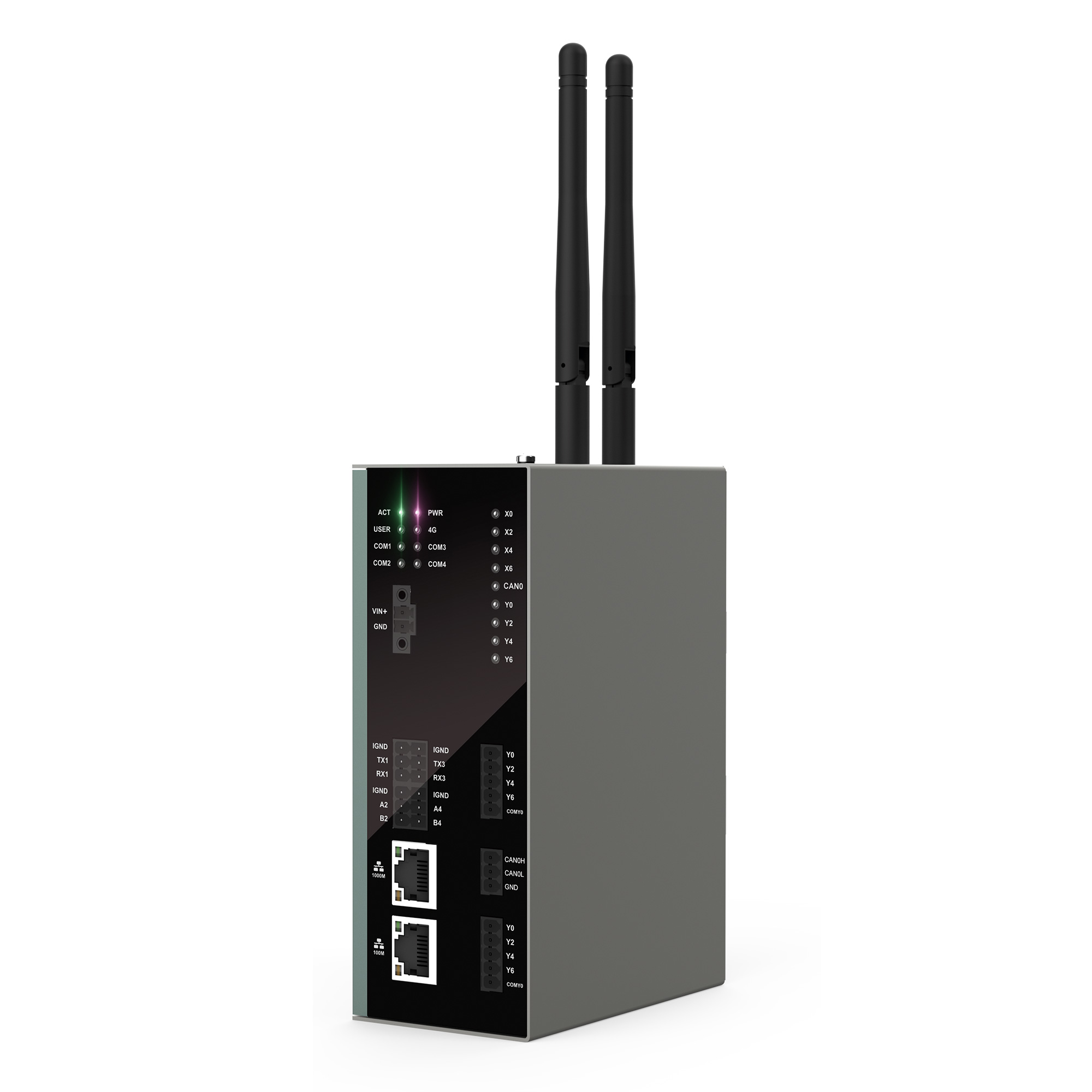
The ED-IPC2600 series represents a formidable line of industrial computers built upon the Raspberry Pi CM4 platform, engineered to deliver high reliability in tough industrial environments. These computers are equipped with a powerful Broadcom BCM2711 processor, which features a quad-core Cortex-A72 CPU based on the 64-bit ARM v8 architecture, running at a speed of 1.5GHz. They also offer up to 8GB of LPDDR4 RAM and up to 32GB of eMMC storage, with the added flexibility of Micro-SD Card and M.2 NVMe SSD support for storage expansion.
The ED-IPC2600 series boasts dual Ethernet connectivity, with one Gigabit Ethernet port and one 100M Ethernet port, providing robust network capabilities. For serial communication, these units feature 2 isolated RS232 and 2 isolated RS485 interfaces, complete with electrostatic and surge protection. Depending on the model, they also offer a varying number of isolated digital inputs (DI) and digital outputs (DO), all equipped with LED indicators and protection for overcurrent and electrostatic discharge.