


 En
En


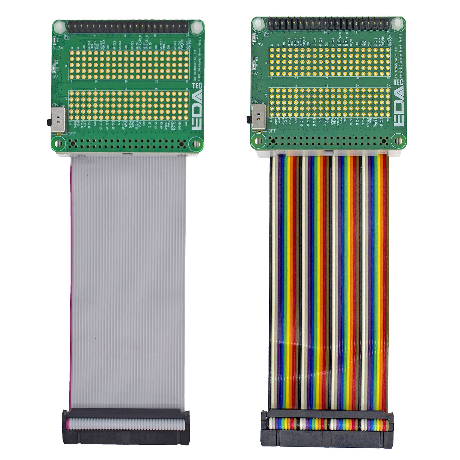
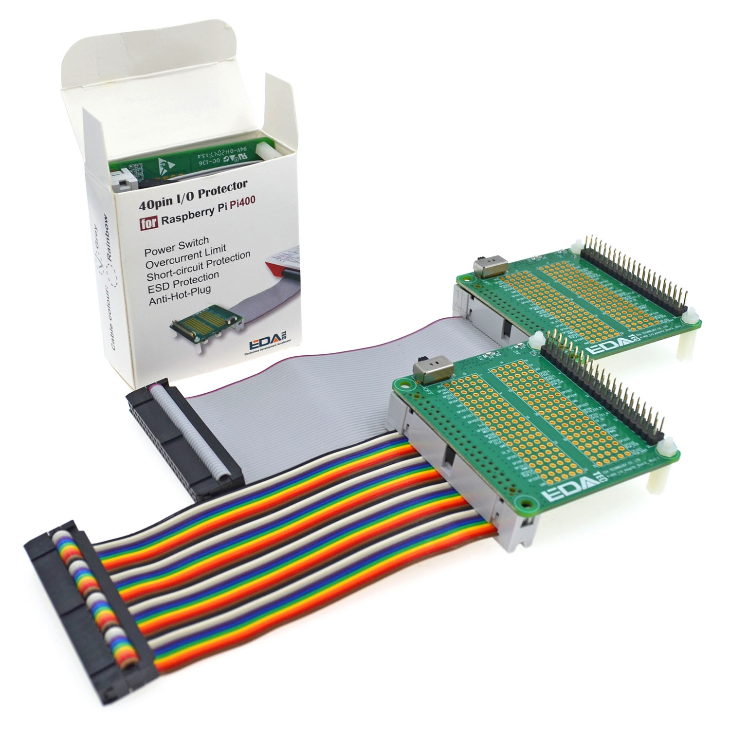
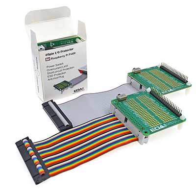
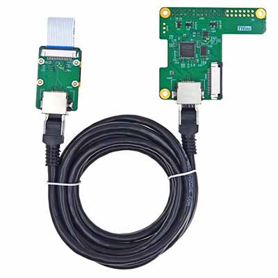
40pin GPIO Protector are made of a 40pin ribbon cable & a circuit board, the 40pin ribbon cable is to lead 40pin GPIO signals from Pi 400, Pi 500, Pi 500+ to the circuit board, the circuit board provides a seriesof functions to protect Pi 400, Pi 500, Pi 500+ computer.
A tiny switch at the left board edge is to control +5V & +3.3V power supply for the daughter board, the user can switch off the daughter board by switching the tiny switch at “OFF” position, when the user wants to install the daughter board on the 40pin connector, he/she doesn’t have to shut down Pi 400, Pi 500, Pi 500+, just need to switch off the power of 40pin GPIO Protector, it protects Pi 400, Pi 500, Pi 500+ from damage due to hot plug.
All of 40 signals from Pi 400, Pi 500, Pi 500+ are protected by ESD immunity IC including power signal, ESD immunity IC will absorb the energy of ESD which may come from the daughter boards.
All of GPIO signals are protected by current limit resistors-33ohm, short circuit between GPIOs and GPIO to GND, 5V or 3.3V won’t damage the IO of Pi 400, Pi 500, Pi 500+.
Although PMU of Pi 400, Pi 500, Pi 500+ provides the over-current protection, Pi 400, Pi 500, Pi 500+ won’t properly work when PMU is on protection mode. Over-current limit circuit on GPIO protector limits 2A@5V and 1.5A@3.3V maximal current draw from Pi 400, Pi 500, Pi 500+, it void the PMU of Pi 400, Pi 500, Pi 500+ to shut down the system due to short circuit or over current of daughter board, a green LED indicates the status of 3.3V power supply for daughter board, a red LED indicates the status of 5V power.
When daughter board draw too much power from Pi 400, Pi 500, Pi 500+, LED will blink.
2pcs 220uF capacitors stabilise the power supply of 5V and 3.3V respectively, 5*40pin bread board allows the user to do some experiment without additional cost.
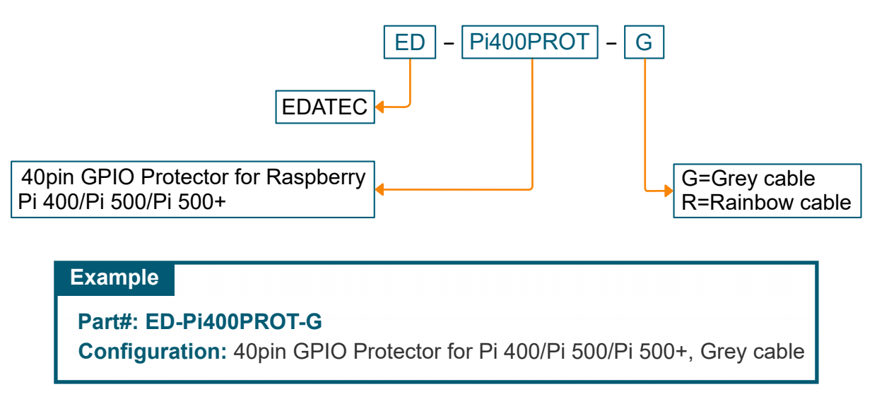
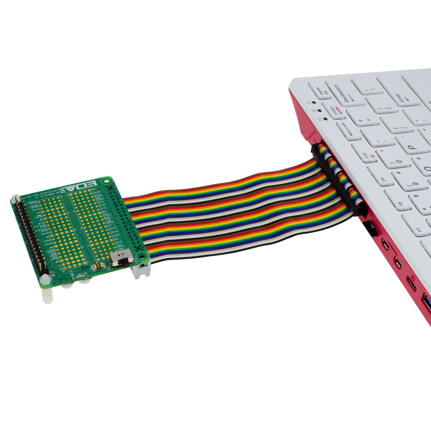
The IO board comes with a 40pin ribbon cable, which is Grey and rainbow colors optional, 40pin black female connector with anti-reverse insertion at one end is to connect 40pin male connector at the back of Pi 400, Pi 500, Pi 500+, the user can install the daughter board on the IO board.
All of materials used on this product are RoHS compliant.
Installation Guide
Note: The installation steps are identical for the Raspberry Pi 400, Pi 500, and Pi 500+, and are only illustrated here using the Pi 400 as an example.
40pin GPO Protector include 40pin GPIO Extender, if you already have 40 pin GPIO Protector, there is no need to buy 40 Pin GPIO Extender.
1. Set the switch of 40pin GPIO protector at the “OFF” position.
2. Install daughter board on the top of 40pin GPIO protector, make sure the holes on the four corners between GPIO protector and daughter boards are aligned.
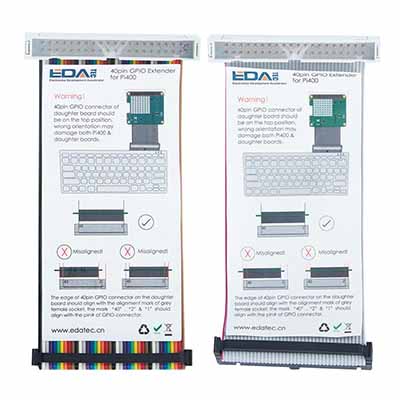
3. Insert 40pin black female connector into 40pin male connector at the back of Pi 400. If black female connector can’t be inserted into Pi 400, the orientation of the black female connector should be wrong, please reverse the cable and re-insert.
4. Power on Pi 400, turn the switch to “ON” position.
5. If you want to remove daughter board from 40pin GPIO protector, turn the switch to “OFF”position, remove the daughter board from 40pin GPIO protector. (You don’t have to power off Pi 400 when you do it)