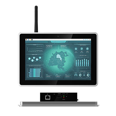
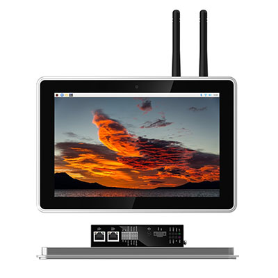
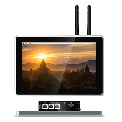
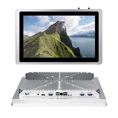
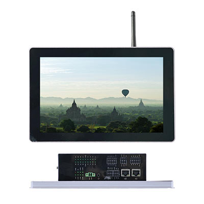
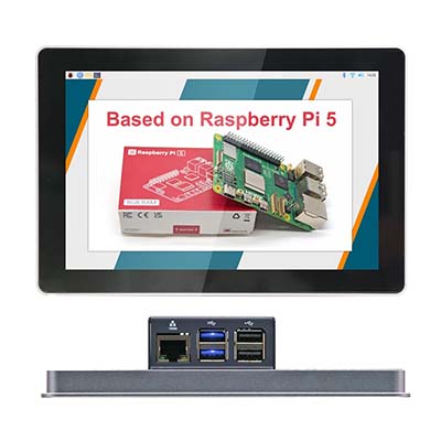
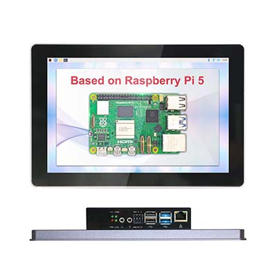
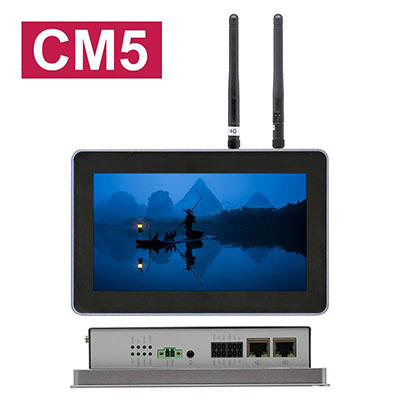
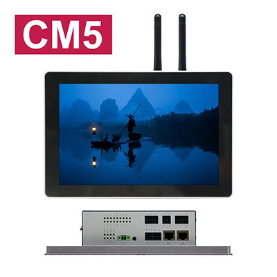
ED-HMI2630-101C Features |
10.1" TFT, resolution 1280x800, multi-point capacitive touch screen
|
Broadcom BCM2711, quad core Arm Cortex-A72 (ARM v8) 64-bit SoC @ 1.5GHz
|
Up to 8GB LPDDR4 RAM and 32GB eMMC storage |
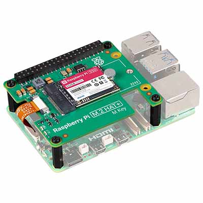
Support Micro SD card and M.2 NVMe SSD storage expansion |
Dual Lans, 1 x Gigabit Ethernet and 1 x 100M Ethernet
|
4 x isolated RS232/485 with electrostatic and surge protection |
2 x isolated CAN with led indicator, support CAN 2.0B standard
|
8 x isolated DI with led indicator, support AC input
|
8 x isolated DO with led indicator, support overcurrent protection |
2.4GHz and 5GHz dual-band Wi-Fi, Bluetooth and 4G LTE |
Wide voltage power input range of DC 9V~36V with reverse polarity protection, overvoltage protection and overcurrent protection
|
Integrated supercapacitor (backup power supply, optional) , RTC, Watch Dog, EEPROM and crypto authentication
|
Embedded installation, compatible with VESA standard bracket installation
|
Document Download
ED-HMI2630-101C Datasheet |
Specifications
System | |
CPU | Broadcom BCM2711, quad core Arm Cortex-A72 (ARM v8) 64-bit SoC @ 1.5GHz |
VPU |
H.265(HEVC), up to 4Kp60 decode
H.264, up to 1080p60 decode, 1080p30 encode
|
GPU | OpenGL ES 3.1 & Vulkan 1.0 |
Memory | Options for 1GB, 2GB, 4GB, 8GB LPDDR4-3200 SDRAM |
Storage |
Options for 8GB, 16GB, 32GB eMMC storage
Micro SD card (user storage expansion)
M.2 NVMe SSD (options for 128GB, 256GB, 512GB)
|
Software
|
|
Operating System |
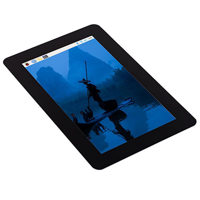
- Raspberry Pi OS(Desktop) 32-bit
- Raspberry Pi OS(Lite) 32-bit
- Raspberry Pi OS(Desktop) 64-bit
- Raspberry Pi OS(Lite) 64-bit
|
Front I/O | |
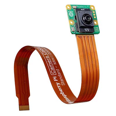
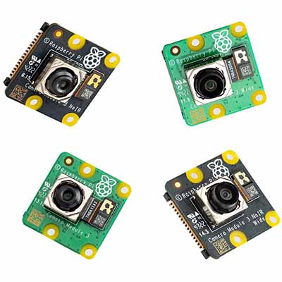
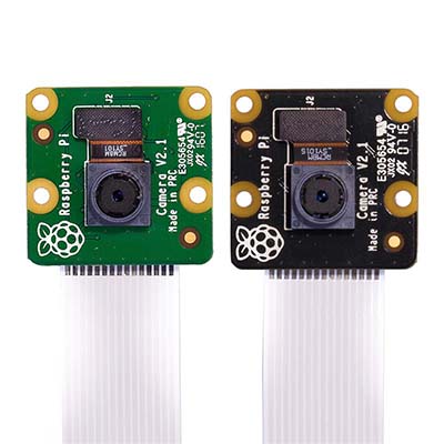
Camera | Built-in 8-megapixel front camera(optional). |
Side I/O
|
|
Power |
1 x DC IN, 2-Pin 3.5mm spacing phoenix terminals with screw holes.
It supports 9V~36V input, the signal is defined as VIN+/GND.
|
RS485/232 |
12-Pin 3.5mm spacing phoenix terminals with IO isolator, which are equipped with electrostatic and surge protection. Different numbers of RS232 and RS485 ports can be selected according to actual application. The signal of RS485 is defined as IGND/A/B, and the signal of RS232 is defined as IGND/TX/RX.
ED-HMI2632-101C: 2 x RS485 + 2 x RS232
ED-HMI2633-101C: 3 x RS485 + 1 x RS232
ED-HMI2634-101C: 4 x RS485
|
Audio
|
1 x Audio In/Stereo Out, 3.5mm audio jack connector. It can be used as MIC IN and LINE OUT.
- When a headphone is connected, the audio output switches to the headphone.
- When no headphone is connected, the audio output switches to the speaker.
|
1000M Ethernet
|
1 x adaptive 10/100M ethernet port, RJ45 connector. It can be used to access the network.
|
100M Ethernet
|
1 x Audio port, 3.5mm audio jack connector, 4-pole stereo audio. |
CAN |
2 x CAN ports, 6-Pin 3.5mm spacing phoenix terminals
- Isolation Protection: 3 KV
- CAN Protocol: CAN 2.0B
- Baud Rate: 10~1000 kbps
- Signals: CANH, CANL, GND
|
DI |
8 x DI ports, 10-Pin 3.5mm spacing phoenix terminals
- Sensor Type: Wet Contact (NPN & PNP), Dry Contact
- Isolation Protection: 5 KV
- Every 4 DI share one common pin (called COM): X0, X2, X4 and X6 share COMX0; X1, X3, X5 and X7 share COMX1
- DI to COM:
ON: 5~30 VDC or -30~-5 VDC
OFF: 0~2 VDC or -2~0 VDC
|
DO |
8 x DO ports, 10-Pin 3.5mm spacing phoenix terminals
- Sensor Type: NPN
- Isolation Protection: 5 KV
- Output: 5~36 VDC (24 VDC is recommended), maximum current is 1.5A(per channel)
|
SD Card Slot
|
1 x Micro SD card slot, which is used to install SD card for storing user data. |
SIM Card Slot
|
1 x Nano SIM card slot, which is used to install SIM card for getting 4G signal. |
Micro USB |
1 x PROGRAMMING port, which supports to flash to eMMC for the system.
|
HDMI
|
1 x HDMI port, type A connector. It is compatible with HDMI 2.1 and supports 4K 60Hz. |
USB 2.0 | 2 x USB 2.0 ports, type A connector, supporting up to 480Mbps. |
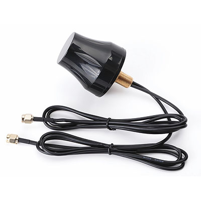
Antenna | 2 x SMA ports, using to connect 4G antenna and Wi-Fi/BT antenna. |
Speaker | 1 x PA output, built-in a 4Ω 3W speaker. |
Buttons and Indicators | |
Reset | 1 x Reset button, which can reset the device. |
PWR | 1 x red power indicator, which is used to check the status of device power-on and power-off. |
4G | 1 x green 4G indicator, which is used to check the status of 4G signal. |
ACT
|
1 x green system indicator, which is used to check the working status of device. |
USER |
1 x green user indicator, user can customize a status according to actual application.
|
COM1~COM4 |
4 x green UART indicators, using to check the communication status of UART ports.
|
CAN0~CAN1 |
2 x green CAN indicators, using to check the communication status of CAN ports.
|
X0~X7 | 8 x green DI indicators, using to check the input status of DI ports. |
Y0~Y7
|
8 x green DO indicators, using to check the output status of DO ports.
|
Expansion I/O | |
12V 1A |
3 x DC OUT, 2-Pin 2.0mm spacing WTB connector, supporting 12V 1A output.
These pins are defined as GND/12V, reserving to provide power supply for extended LCD.
|
10-Pin GPIO |
1 x GPIO Pin Header, 2x5-Pin 2.54mm spacing, using to lead out the expansion GPIO ports. User can customize the function according to actual application, these pins are defined as 8xGPIO/3V3/GND.
|
USB | 1 x USB 2.0, 5-Pin 1.5mm spacing WTB connector, supporting to expand the USB 2.0 port. |
M.2 B
|
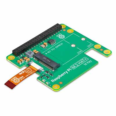
1 x M.2 B, M.2 B Key connector, supporting to connect SSD. It is compatible with M.2 2230 and M.2 2242.
|
Expansion Performance | |
EEPROM
|
Supports 4K byte storage and improves the ease of use of device. |
Crypto Authentication
|
It can be matched to realize the required upper layer application and improves the security of device.
|
RTC
|
RTC with 1F SuperCAP backup, which can ensure that the system clock is not affected by device power-off. We also provide a battery base, and you can buy a CR1220 battery backup for RTC.
|
Buzzer |
A tip or an abnormity can be configurated according to actual application, which realizes the alarm function.
|
Watch Dog*
|
This function has been reserved on hardware. But we need additional software to support it, which is under development.
|
LCD | |
LCD Size | 10.1" TFT |
Resolution | 1280x800 |
Colors | 16.7MB |
Active Area | 216.576mm(H) x 135.36mm(V) |
Backlight | LED |
MTBF | >30000h |
Luminance | 400cd/m^2 |
Contrast Ratio | 1000:1 |
Response Time | 30ms |
Viewing Angle(CR≥10) | 80°(L)/80°(R)/80°(U)/80°(D) |
Touch Screen | |
Type | Multi-point Capacitive Touch Screen |
Transmittance | ≥85% |
Connection Method | COF |
Controller Interface | I2C |
Driver Support | Linux |
Multi-touch | 10 points |
Surface Hardness | 6H |
Electrical Characteristics | |
Input Voltage | 9V ~ 36V DC |
Maximum Power Consumption |
25W |
Mechanical Characteristics
|
|
Dimensions | 258mm x 172mm x 61.5mm (WxDxH) |
Weight | 1.3Kg |
Installation | Embedded front installation |
Wireless
|
|
Wi-Fi/Bluetooth (optional)
|
2.4GHz & 5GHz dual-band Wi-Fi and Bluetooth with antenna.
- 2.4GHz Wi-Fi: Compatible with IEEE 802.11 b/g/n
- 5GHz Wi-Fi: Compatible with IEEE 802.11 a/n/ac
- The Bluetooth supports 2402MHz ~ 2480MHz frequency
|
4G(optional)
|
Connect with various 4G LTE modules through the Mini PCIe interface, with antenna.
- EC20-CE Module (China/India)
LTE FDD: B1/B3
LTE TDD: B38/B39/B40/B41
TDSCDMA: B34/B39
WCDMA: B1
CDMA 1x/EVDO: BC0
GSM: 900/1800MH
- EC25-AFX Module (North America)
LTE-FDD: B2/B4/B5/B12/B13/B14/B66/B71
LTE-TDD
WCDMA: B2/B4/B5
GSM/EDGE
- EC25-AUX Module (Latin America/Australia/New Zealand)
LTE-FDD: B1/B2/B3/B4/B5/B7/B8/B28
LTE-TDD: B40
WCDMA: B1/B2/B4/B5/B8
GSM/EDGE: B2/B3/B5/B8
- EC25-EUX Module (Europe/Middle East/Africa/Thailand)
LTE-FDD: B1/B3/B7/B8/B20/B28A
LTE-TDD: B38/B40/B41
WCDMA: B1/B8
GSM/EDGE: B3/B8
|
Environmental & Regulatory | |
Operating Temperature | -20℃~60℃ |
Storage Temperature | -25℃~60℃ |
Ambient Humidity | 5% ~ 95% (non-condensing) |
Certifications |
FCC
- FCC 47 CFR Part 15 Subpart B
CE
- EN IEC 62368-1/EN IEC 62311/EN IEC 61000-3-2/EN IEC 61000-3-3
- EN 55032/EN 55035/
- EN 301 489-1/EN 301 489-3/EN 301 489-17/EN 301 489-52
- EN 301 328/EN 301 440/EN 301 511/EN 301 908-1/EN 301 908-2
|
System Block Diagram
Dimension Unit:mm
Order Information
Optional Accessory
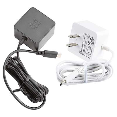
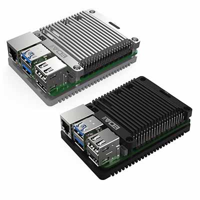
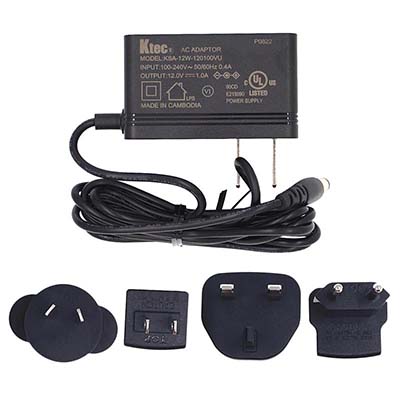
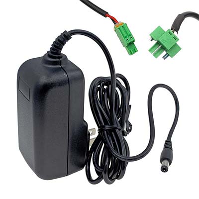
You can choose a power adapter according to actual needs.More Products
ED-HMI Series Selection Guide |
|||||||||
Model No. | CPU | LCD Size | Audio Input & Output | #Ethernet | RS485/RS232 | 4G | SSD | DI/DO | Supercaps |
ED-HMI2002 | Pi 4 | 7"/10.1" | √ | x 1 | - | - | - | - | - |
ED-HMI2020 | CM4 | 7"/10.1" | √ | x 1 | - | - | - | - | - |
ED-HMI2120 | CM4 | 7"/10.1" | √ | x 2 | √ | √ | √ | - | √ |
ED-HMI2220 | CM4 | 7"/10.1" | √ | x 3 | - | √ | √ | - | √ |
ED-HMI2320 | CM4 | 12.1"/15"/15.6"/17"/21.5" | √ | x 1 or x 2 | √ | √ | √ | - | - |
ED-HMI2630 | CM4 | 10.1" | √ | x 2 | √ | √ | √ | √ | √ |
ED-HMI3010 | Pi 5 | 7"/10.1" | - | x 1 | - | - | - | - | - |
ED-HMI3020 | Pi 5 | 7"/10.1" | √ | x 1 | √ | - | √ | - | - |