
1 Hardware Manual
This chapter introduces the product overview, package contents, appearance, buttons, indicators, and interfaces.
1.1 Overview
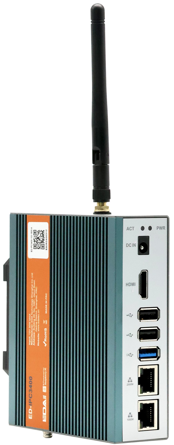
The ED-IPC3400 is an industrial computer based on the Raspberry Pi CM5. Depending on different application scenarios and user requirements, it can be configured with various specifications of RAM, eMMC, and SD card.
- Available RAM options: 2GB, 4GB, 8GB, and 16GB.
- Available eMMC options: 16GB, 32GB, and 64GB.
- Available SD card options: 32GB and 64GB.
The ED-IPC3400 features HDMI, USB 2.0/3.0, and dual Ethernet ports (2.5G + 1G), supports Wi-Fi and wired network access, and integrates RTC, EEPROM, and a security chip, significantly enhancing usability and reliability in industrial control and IoT applications. Additionally, it includes a built-in M.2 M Key expansion interface, supporting optional 128GB/256GB/512GB SSDs or a Hailo‑8 AI module (13 TOPS), efficiently powering high-compute industrial scenarios such as machine vision.
1.2 Package Contents
- 1 x ED-IPC3400 Unit
- [Optional Wi-Fi/BT Version] 1 x 2.4GHz/5GHz Wi-Fi/BT Antenna
1.3 Appearance
Describes the functions and definitions of the interfaces on each panel.
1.3.1 Front Panel
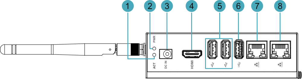
Describes the types and definitions of the front panel interfaces.
| NO. | Function Definition |
|---|---|
| 1 | 1 x System Status Indicator (Green), indicates system read/write data status. |
| 2 | 1 x Power Indicator (Red), indicates device power-on status. |
| 3 | 1 x DC Input, DC Jack (5.5x2.5) connector, supports 9V~28V input. |
| 4 | 1 x HDMI, Type-A interface, compatible with HDMI 2.0, supports 4K 60Hz resolution for connecting to a monitor. |
| 5 | 2 x USB 2.0, Type-A interfaces, each supporting up to 480Mbps transfer rate. |
| 6 | 1 x USB 3.0, Type-A interface, supports up to 5Gbps transfer rate. |
| 7 | 1 x 2500M Ethernet Interface, RJ45 connector with LED indicator, auto-negotiating 10/100/1000M/2500M, for Ethernet connection. |
| 8 | 1 x 1000M Ethernet Interface, RJ45 connector with LED indicator, auto-negotiating 10/100/1000M, for Ethernet connection. |
1.3.2 Rear Panel
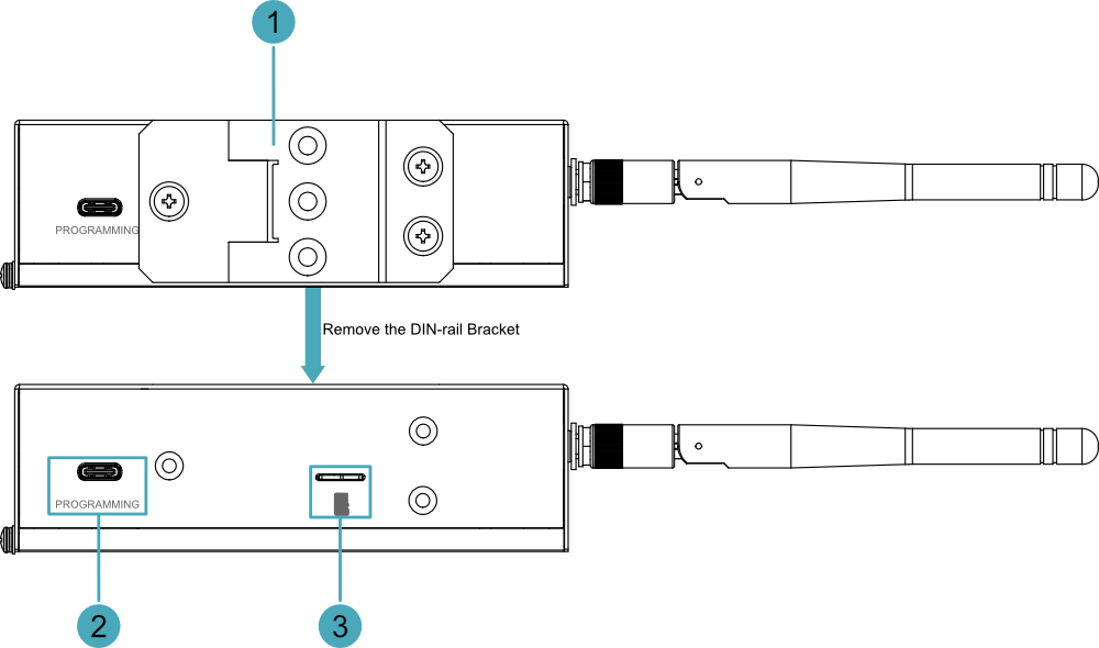
Describes the types and definitions of the rear panel interfaces.
| NO. | Function Definition |
|---|---|
| 1 | 1 x DIN Rail Bracket, mounts the ED-IPC3400 unit onto a DIN rail. |
| 2 | 1 x Type-C USB Interface, supports eMMC flashing via this interface. |
| 3 | 1 x Micro SD Card Slot, supports installing a Micro SD card for system boot. Note: The installed Micro SD card is only effective when using CM5Lite. |
1.3.3 Side Panel
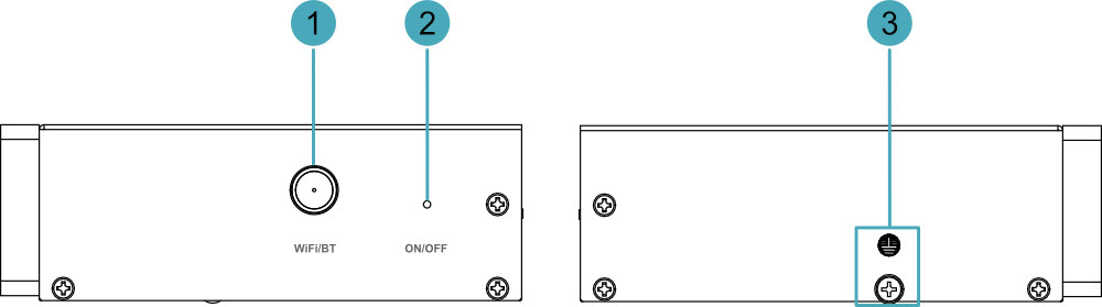
Describes the types and definitions of the side panel interfaces.
| NO. | Function Definition |
|---|---|
| 1 | 1 x Wi-Fi/BT Antenna Connector (Optional), SMA connector, for connecting a Wi-Fi/BT antenna. |
| 2 | 1 x ON/OFF Button, recessed button, press to open the shutdown options menu in Desktop systems. |
| 3 | 1 x Ground Terminal, connects to the earth ground of the external power supply. |
1.4 Button
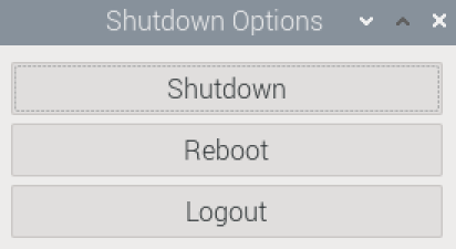
The ED-IPC3400 includes one ON/OFF button. This is a recessed button, marked with "ON/OFF" silkscreen on the casing. In Desktop systems, short pressing the button opens the shutdown options menu, allowing you to choose Shut Down, Reboot, or Logout.
TIP
- In Desktop systems, quickly pressing the ON/OFF button twice in succession will shut down the device directly.
- After shutting down the device by pressing the ON/OFF button twice in succession, a single short press of the ON/OFF button will power on the device.
1.5 Indicator
Describes the various states and meanings of the indicators on the ED-IPC3400.
| Indicator | Status | Description |
|---|---|---|
| PWR | Solid On | Device is powered on |
| Blinking | Device power anomaly, stop supplying power immediately | |
| Off | Device is not powered on | |
| ACT | Blinking | System boot successful and reading/writing data |
| Off | Device is not powered on or not reading/writing data | |
| Yellow indicator of Ethernet port | On | The data transmission is abnormal. |
| Blink | Data is being transmitted over the Ethernet port. | |
| Off | The Ethernet connection is not set up. | |
| Green indicator of Ethernet port | On | The Ethernet connection is in the normal state. |
| Blink | The Ethernet connection is abnormal. | |
| Off | The Ethernet connection is not set up. |
1.6 Interface
Describes the definition and function of each interface on the product.
1.6.1 Micro SD Card
The ED-IPC3400 includes one Micro SD card slot, with the silkscreen marking " ". It supports installing a Micro SD card for system boot.
TIP
The installed Micro SD card is only effective when using CM5Lite.
1.6.2 Power Interface
The ED-IPC3400 includes one power input, using a DC Jack (5.5x2.5) connector, with the silkscreen marking "DC IN". It supports 9V~28V power input.
TIP
It is recommended to use a 12V 4A power adapter.
1.6.3 2500M Ethernet Interface
The ED-IPC3400 includes one auto-negotiating 10/100/1000M/2500M Ethernet interface, with the silkscreen marking "  ". It uses an RJ45 connector. For Ethernet connections, it is recommended to use Cat6 or higher specification cables. The pin definitions for the connector are as follows:
 | Pin ID | Pin Name |
|---|---|---|
| 1 | TX1+ | |
| 2 | TX1- | |
| 3 | TX2+ | |
| 4 | TX2- | |
| 5 | TX3+ | |
| 6 | TX3- | |
| 7 | TX4+ | |
| 8 | TX4- |
1.6.4 1000M Ethernet Interface
The ED-IPC3400 includes one auto-negotiating 10/100/1000M Ethernet interface, with the silkscreen marking "  ". It uses an RJ45 connector. For Ethernet connections, it is recommended to use Cat6 or higher specification cables. The pin definitions for the connector are as follows:
| Pin ID | Pin Name |
|---|---|---|
| 1 | TX1+ | |
| 2 | TX1- | |
| 3 | TX2+ | |
| 4 | TX2- | |
| 5 | TX3+ | |
| 6 | TX3- | |
| 7 | TX4+ | |
| 8 | TX4- |
1.6.5 HDMI Interface
The ED-IPC3400 includes one HDMI interface, with the silkscreen marking "HDMI", standard Type-A interface. It supports connecting an HDMI monitor, with a maximum video output of 4Kp60.
1.6.6 USB 2.0 Interface
The ED-IPC3400 includes two USB 2.0 interfaces, with the silkscreen marking "  ", standard Type-A interfaces. They support connecting standard USB 2.0 peripherals, with a maximum transfer rate of 480Mbps.
1.6.7 USB 3.0 Interface
The ED-IPC3400 includes one USB 3.0 interface, with the silkscreen marking " ", standard Type-A interface. It supports connecting standard USB 3.0 peripherals, with a maximum transfer rate of 5Gbps.
1.6.8 Type-C USB Interface
The ED-IPC3400 includes one Type-C USB interface, with the silkscreen marking "PROGRAMMING". It supports flashing the device's eMMC by connecting to a PC.
1.6.9 Antenna Interface (Optional)
The ED-IPC3400 includes one SMA antenna interface, with the silkscreen marking "WiFi/BT", for connecting a Wi-Fi/BT antenna.
1.6.10 Internal Interfaces
This section describes the internal interfaces reserved on the ED-IPC3400. Access requires opening the device case and can be expanded based on actual requirements.
1.6.10.1 MIPI Interface
The ED-IPC3400 includes two MIPI interfaces, using 22-Pin FPC connectors. These are DPHY0 (MIPI0) and DPHY1 (MIPI1), both supporting expansion connections for Raspberry Pi Camera and Raspberry Pi Touch Display 2.
1.6.10.2 40-Pin GPIO Header
The ED-IPC3400 features an internal 40-pin GPIO connector with the pin definitions listed below:
| Pin | Definition | Pin | Definition |
|---|---|---|---|
| 1 | 3.3V | 2 | 5V |
| 3 | GPIO2 (Pulled up to 3.3V by default; configured for I2C function as SDA) | 4 | 5V |
| 5 | GPIO3 (Pulled up to 3.3V by default; configured for I2C function as SCL) | 6 | GND |
| 7 | GPIO4 | 8 | GPIO14 |
| 9 | GND | 10 | GPIO15 |
| 11 | GPIO17 | 12 | GPIO18 |
| 13 | GPIO27 | 14 | GND |
| 15 | GPIO22 | 16 | GPIO23 |
| 17 | 3.3V | 18 | GPIO24 |
| 19 | GPIO10 | 20 | GND |
| 21 | GPIO9 | 22 | GPIO25 |
| 23 | GPIO11 | 24 | GPIO8 |
| 25 | GND | 26 | GPIO7 |
| 27 | ID_SD5 (Assigned) | 28 | ID_SC5 (Assigned) |
| 29 | GPIO5 | 30 | GND |
| 31 | GPIO6 | 32 | GPIO12 |
| 33 | GPIO13 | 34 | GND |
| 35 | GPIO19 | 36 | GPIO16 (Assigned) |
| 37 | GPIO26 | 38 | GPIO20 |
| 39 | GND | 40 | GPIO21 |
1.7 RTC
The ED-IPC3400 integrates an RTC function internally. It provides an RTC battery base by default, supporting a CR1220 battery as an RTC backup power source.
1.8 Security Chip
The ED-IPC3400 integrates a security chip (Microchip ATSHA204A) internally. It can work with user-level upper-layer applications to securely store critical information such as device private keys and digital certificates, ensuring that this information cannot be read or exported by software, effectively preventing device cloning or forgery.
1.9 EEPROM
The ED-IPC3400 integrates an internal EEPROM with 4K Bytes of storage capacity. It allows users to write and save small amounts of critical data.
1.10 Hailo‑8 (13 TOPS) AI Acceleration Module (Optional)
The ED-IPC3400 supports an optional Hailo‑8 (13 TOPS) AI module. Paired with the Raspberry Pi CM5, it enables AI edge computing with high computing power, suitable for industrial scenarios such as machine vision.