
5 Configuring System
This chapter describes the specific operations for system configuration.
5.1 Finding Device IP
5.2 Remote Login
5.3 Configuring Storage Devices
5.4 Configuring Ethernet IP
5.5 Configuring Wi-Fi
5.6 Configuring Bluetooth
5.7 Configuring RTC
5.8 Configuring MIPI Interfaces (Optional)
The ED-IPC3400 includes two MIPI interfaces (located inside the device), using 22-Pin FPC connectors. These are DPHY0 (MIPI0) and DPHY1 (MIPI1), both supporting expansion connections for Raspberry Pi Camera and Raspberry Pi Touch Display.
TIP
These interfaces are located inside the device and require opening the device casing for access. They are reserved interfaces only.
The two MIPI interfaces support the following Raspberry Pi Camera/Touch Display models for expansion connection:
- Camera:
- OmniVision OV5647
- Sony IMX219
- Sony IMX296
- Sony IMX477
- Sony IMX708
- Raspberry Pi Touch Display 2 (5-inch and 7-inch)
Before using a Raspberry Pi Camera/Touch Display on the ED-IPC3400, you need to perform the relevant configuration, add the Camera and Touch Display parameters, and then connect the Raspberry Pi Camera/Touch Display. The following sections describe the specific operations.
Preparation:
The ED-IPC3400 device has been successfully started.
Steps:
- After the device has started successfully, open a command terminal and execute the following command to open the
config.txtconfiguration file.
sudo nano /boot/firmware/config.txt
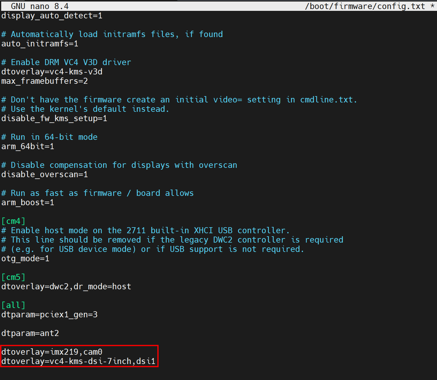
- Add the information for the Camera and Touch Display to be used at the end of the configuration file. As shown in the red box in the image below, MIPI0 is configured as a Sony IMX219 Camera, and MIPI1 is configured as a 7-inch Raspberry Pi Touch Display 2.
Other configuration parameter examples:
- Configure both MIPI0 and MIPI1 as Sony IMX219 Cameras.
dtoverlay=imx219,cam0
dtoverlay=imx219,cam1
- Configure both MIPI0 and MIPI1 as 7-inch Raspberry Pi Touch Display 2.
dtoverlay=vc4-kms-dsi-ili9881-7inch,dsi0
dtoverlay=vc4-kms-dsi-ili9881-7inch,dsi1
- Configure MIPI0 as a 7-inch Raspberry Pi Touch Display 2 and MIPI1 as a Sony IMX219 Camera.
dtoverlay=vc4-kms-dsi-ili9881-7inch,dsi0
dtoverlay=imx219,cam1
TIP
- If using a different Camera model, modify the Camera model in the configuration parameters accordingly. For example, if using a Sony IMX296, change
imx219toimx296. - If using a 5-inch Touch Display 2, modify the screen size in the configuration parameters accordingly. For example, if using a 5-inch Raspberry Pi Touch Display 2, change
vc4-kms-dsi-ili9881-7inchtovc4-kms-dsi-ili9881-5inch. - For more information about Raspberry Pi Camera configuration, please refer to Raspberry Pi Camera.
- For more information about Raspberry Pi Touch Display 2 configuration, please refer to Raspberry Pi Touch Display 2.
Press
Ctrl+Oto save the file, then pressEnter, and finally pressCtrl+Xto exit the file editing mode.Execute the following command to restart the device and apply the configuration.
sudo reboot
Disconnect the ED-IPC3400 device from its power source.
Install the Raspberry Pi Camera/Touch Display onto the ED-IPC3400 motherboard via the FPC interface.
Hailo-8 Module (Optional)
The ED-IPC3400 supports an optional Hailo‑8 (13 TOPS) AI module. The pre-installed operating system from our company comes with the corresponding configuration and software installation for Hailo-8 (a fixed version) by default. If users install a standard Raspberry Pi OS themselves, they can refer to the following instructions for configuration and software installation.
Preparation:
The ED-IPC3400 device has been successfully started.
Steps:
- Modify the
config.txtconfiguration file to enable the PCIe Gen3.0 interface.
a. After the device has started successfully, open a command terminal and execute the following command to open the config.txt configuration file.
sudo nano /boot/firmware/config.txt
b. Add the following content to the configuration file.
dtparam=pciex1_gen=3
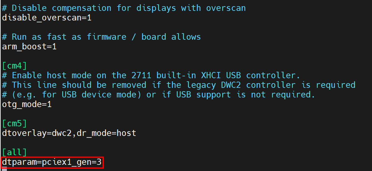
c. Press Ctrl+O to save the file, then press Enter, and finally press Ctrl+X to exit the file editing mode.
d. Execute the following command to restart the device and apply the configuration.
sudo reboot
- Execute the following commands in sequence to install the Hailo software.
sudo apt install dkms
sudo apt install hailo-all
- Execute the following command to view the detailed information of the installed Hailo software.
dpkg -l | grep hailo
- For more specific configuration details regarding the Hailo module, please refer to Raspberry Pi AI Software documentation.
TIP
The version information of the Hailo software built into the pre-installed operating system from our company is as follows:

5.10 Configuring Security Chip
The ED-IPC3400 integrates a security chip (Microchip ATSHA204A) internally. The specific usage of the security chip depends on the user's actual upper-layer application. Since customer requirements vary, the following sections only describe the download/compilation of the encryption library source code corresponding to the security chip and a test example for the security chip.
Preparation:
The ED-IPC3400 device has been successfully started.
Steps:
- Modify the
config.txtconfiguration file to enable I2C and the security chip.
a. After the device has started successfully, open a command terminal and execute the following command to open the config.txt configuration file.
sudo nano /boot/firmware/config.txt
b. Add the following content to the configuration file.
dtparam=i2c_arm=on
dtparam=ant2
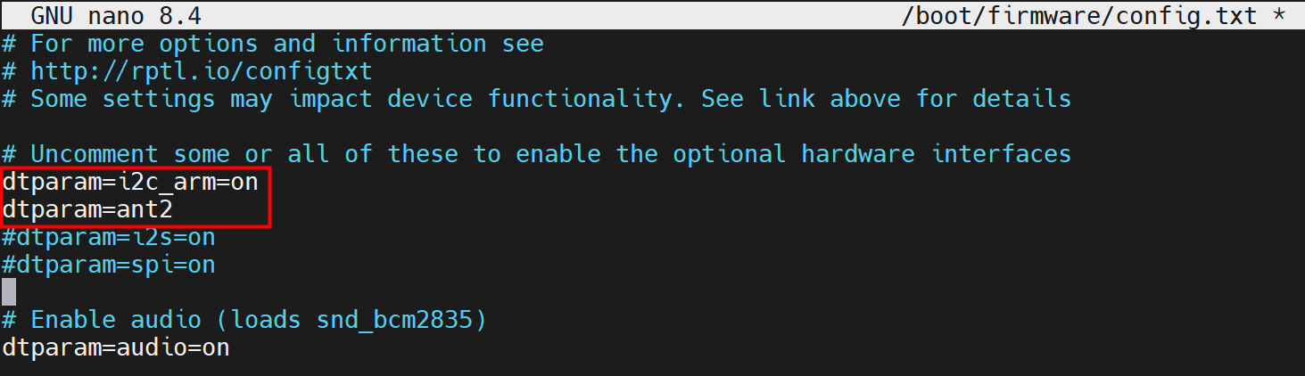
c. Press Ctrl+O to save the file, then press Enter, and finally press Ctrl+X to exit the file editing mode.
d. Execute the following command to restart the device and apply the configuration.
sudo reboot
(Optional) Obtain the CryptoAuthLib v3.7.0 encryption library source code from GitHub at the following path: CryptoAuthLib v3.7.0。
(Optional) Compile the downloaded encryption library source code on the ED-IPC3400 device.
mkdir build && cd build
cmake .. -DATCA_HAL_I2C=ON -DATCA_BUILD_SHARED_LIBS=on -DATCA_USE_ATCAB_FUNCTIONS=ON
make -j4
sudo make install
- Install Python to allow Python to import cryptoauthlib.
cd ~/cryptoauthlib-3.7.0/python
sudo cp -r cryptoauthlib/ $(python3 -c "import site; print(site.getsitepackages()[0])")
- Test whether the security chip can be used normally through the sample code.
#!/usr/bin/env python3
"""
CryptoAuthLib 3.7.0 + ATSHA204A @ i2c-1 0x64
"""
import ctypes

from cryptoauthlib.library import load_cryptoauthlib,AtcaReference
load_cryptoauthlib()

from cryptoauthlib.atcab import (
    atcab_init, atcab_release,
    atcab_info, atcab_read_serial_number,
    atcab_random, atcab_is_locked
)
# from cryptoauthlib.iface import cfg_ateccx08a_i2c_default
from cryptoauthlib.iface import cfg_atsha20xa_i2c_default

cfg = cfg_atsha20xa_i2c_default()

cfg.cfg.atcai2c.u.slave_address = 0x64 << 1
cfg.cfg.atcai2c.bus = 1
print(f"slave_address = 0x{cfg.cfg.atcai2c.u.slave_address:02X}")

st = atcab_init(cfg)
if st != 0:
    print(f"❌ atcab_init failed: {st}")
    exit(1)

print("ATSHA204A@0x64 initialized ok.")

rev = bytearray(4)
atcab_info(rev)
print(f"Rev : {rev.hex()}")

sn = bytearray(9)
atcab_read_serial_number(sn)
print(f"SN  : {sn.hex()}")

rnd = bytearray(32)
atcab_random(rnd)
print(f"RND : {rnd[:8].hex()}...")

is_locked_cfg = AtcaReference(ctypes.c_bool(False))

status1 = atcab_is_locked(0x00, is_locked_cfg)
if status1 == 0:
    cfg_lock = is_locked_cfg.value
    print(f"Config localed: {cfg_lock}")
else:
    print(f"Config lock status read failed: {status1}")

atcab_release()
print("Test completed.")
TIP
- CryptoAuthLib v3.7.0 offers stable support for the ATSHA204A with complete functionality, so it is recommended to use the CryptoAuthLib v3.7.0 version of the encryption library source code.
- If using the pre-installed operating system from our company, the CryptoAuthLib v3.7.0 encryption library source code is already installed and compiled by default, so Steps 1 and 2 can be skipped.
- If users install a standard Raspberry Pi OS themselves, Steps 1 through 4 must be performed.
5.11 Configuring EEPROM
The ED-IPC3400 integrates an internal EEPROM with 4K Bytes of storage capacity. It allows users to write and save small amounts of critical data. The following sections describe the specific operations for writing and reading data.
Preparation:
The ED-IPC3400 device has been successfully started.
Steps:
- Open a command terminal and execute the following command to create a
.txtfile with a custom name.
nano edatec_hat.txt
edatec_hatrepresents the custom file name.
- Add the content to be written to the EEPROM in the
edatec_hat.txtfile (this is only an example; users can add content as needed).
cat > myhat.txt << 'EOF'
product_uuid 00000000-0000-0000-0000-000000000000
product_id 0x0001
product_ver 0x0001
vendor "My Company"
product "My HAT"
current_supply 0
dt_blob "my-overlay"
EOF
TIP
The content written to the EEPROM has format restrictions. For detailed specifications, please refer to EEPROM Configuration File Description.
Press
Ctrl+Oto save the file, then pressEnter, and finally pressCtrl+Xto exit the file editing mode.Execute the following command to convert the created
.txtfile into a.eepfile recognizable by the EEPROM.
eepmake edatec_hat.txt edatec_hat.eep
- Execute the following command to write
edatec_hat.eepto the EEPROM.
sudo eepflash.sh -w -f=edatec_hat.eep -t=24c32 -d=1
-w: Specifies write mode;-f=edatec_hat.eep: Specifies the file to be written;-t=24c32: Specifies the EEPROM chip model as AT24C32;-d=1: Specifies the I2C bus number.
- Execute the following command to read data from the EEPROM and save it as a binary file named
readback.bin.
sudo eepflash.sh -r -f readback.bin -t=24c32 -d=1
-r: Specifies read mode;-t=24c32: Specifies the EEPROM chip model as AT24C32;-d=1: Specifies the I2C bus number.
- Execute the following command to parse the read
readback.binbinary file.
hexdump -C readback.bin | head -20
20: Specifies displaying 20 lines of information.
TIP
EEPROM read/write cycles have a limited lifespan. Please avoid frequent operations to prevent affecting its service life.