5 Configuring System
This chapter describes the specific operations for system configuration.
5.1 Finding Device IP
Since the ED-IPC1220 does not include an HDMI interface, remote login is required for device management in practical applications, necessitating obtaining the device's IP address.
5.1.1 Querying via Local Serial Port Login
Logging In to the System via Local Serial Port
5.1.2 Querying by Logging into the Router
After the device starts up normally, you can log into the router to view the current device IP.
Preparation:
- The device is connected to the network via a router.
- You have obtained the IP address (e.g., 192.168.X.X) and network password of the router in your network.
Steps:
- Open a browser, enter the router's IP address (e.g., 192.168.X.X) in the address bar, and press
Enterto access the router login interface. - Input the network password as prompted to access the router management interface.
- Find the device's IP address by its hostname in the list of connected devices within the management interface.
TIP
The default hostname for the ED-IPC1220 device is ipc1220.
5.1.3 Querying via Ping in Windows Terminal
Preparation:
- Have a functioning Windows PC.
- Have connected both the ED-IPC1220 and the PC to the same router, so they are on the same IP subnet.
Steps:
- Open the Windows PC's terminal pane as an administrator.
- Execute the following command in the terminal pane to ping the ED-IPC1220 device.
ping -4 ipc1220.local
- ipc1220 represents the device's hostname.
TIP
This method is only applicable when there is only one ED-IPC1220 device on the same subnet.
5.2 Connecting to the Device via SSH
After the device starts up normally, you can choose to connect to it remotely via SSH for configuration or debugging. Users can choose their own remote login tool. The following uses MobaXterm as an example.
Preparation:
- Have a functioning Windows PC with the
MobaXtermtool installed. - Have connected both the ED-IPC1220 and the PC to the same router, so they are on the same IP subnet.
- Have obtained the IP address of the ED-IPC1220.
Steps:
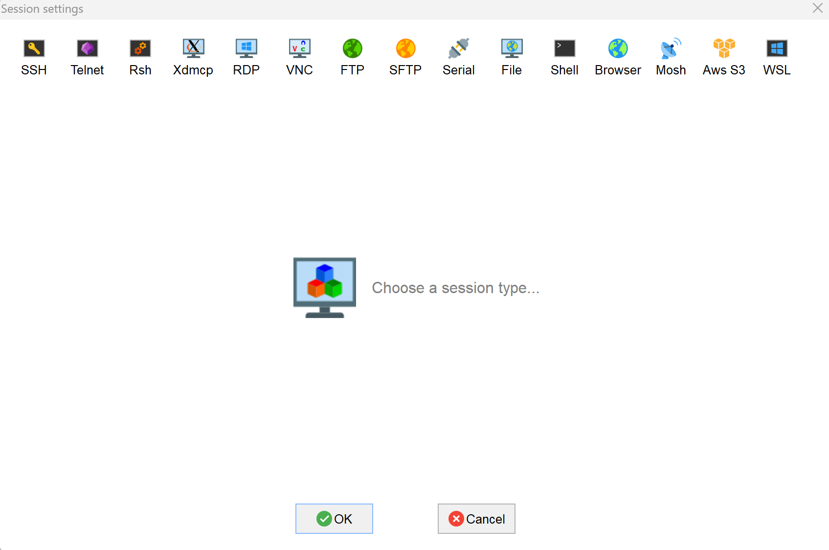
- Open
MobaXterm, click the button to open the session creation window, as shown below.
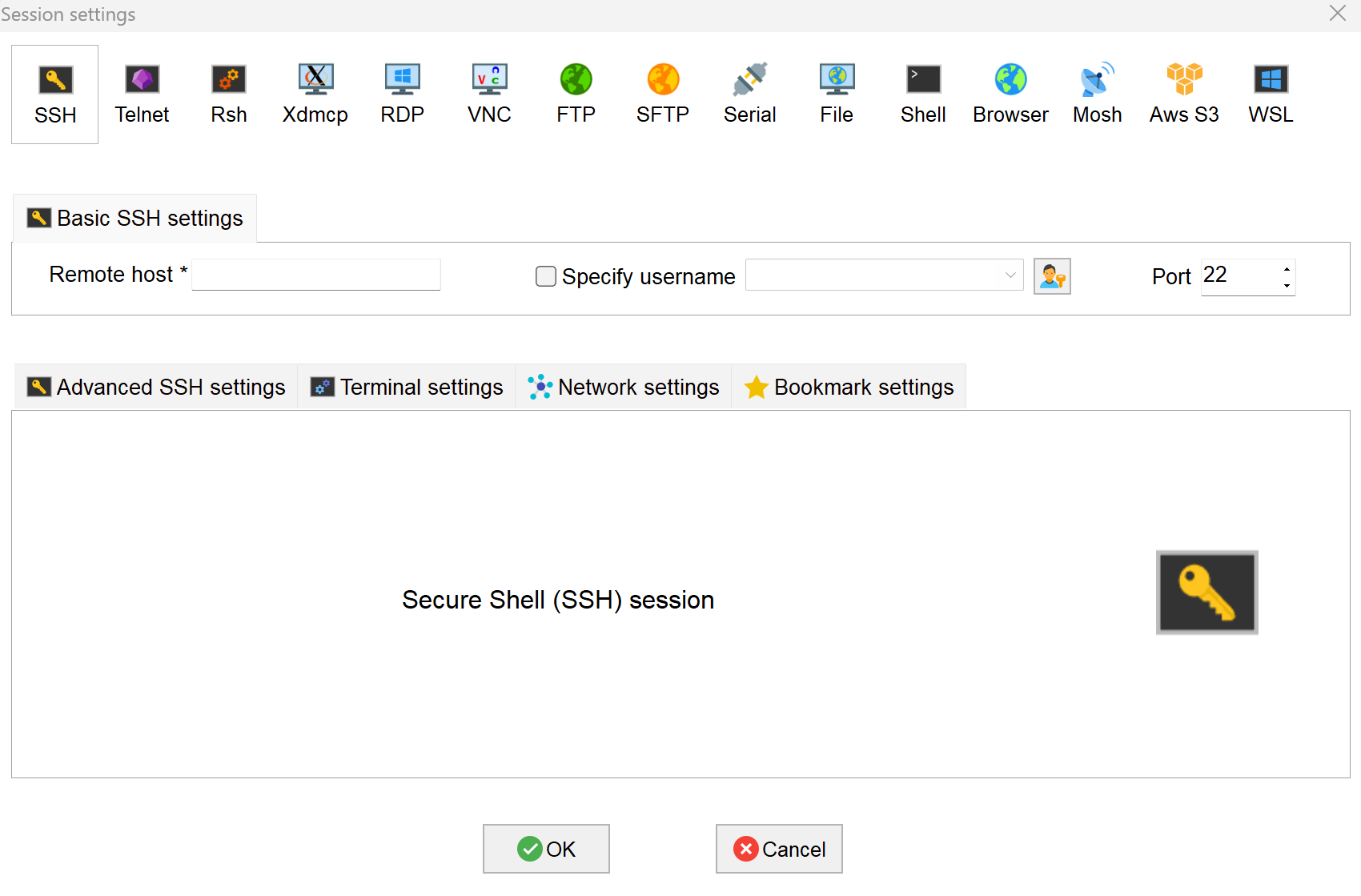
- Click the
 icon in the top-left corner to open the SSH connection interface.
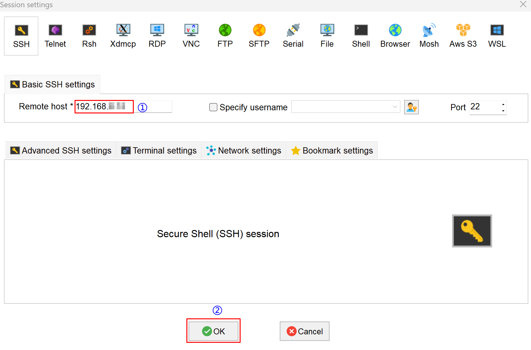
- Input the obtained device IP address, then click "OK".
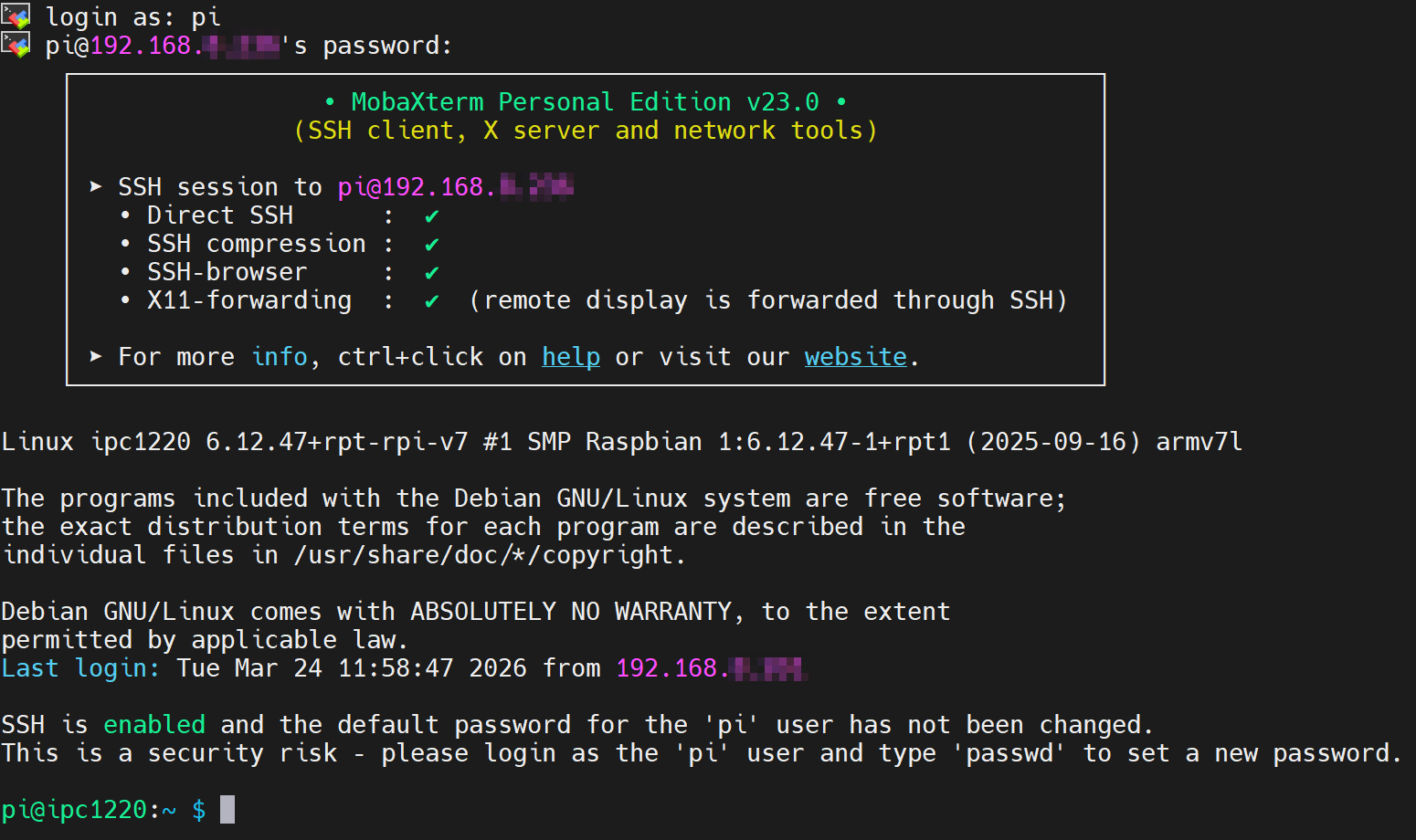
- Click "Accept" in the pop-up prompt box to enter the system login interface.
- Input the username and password as prompted. After successful login, you will enter the system.
TIP
Default username: pi, Default password: raspberry.
5.3 Configuring Storage Devices
5.4 Configuring Ethernet IP
5.5 Configuring Wi-Fi
5.6 Configuring Bluetooth
5.7 Configuring 4G
The 4G function is enabled by default on the ED-IPC1220 device. After inserting the SIM card and powering on the device, wait a few minutes for the 4G network to connect automatically.
5.7.1 Scenarios Without APN Configuration
If the user's 4G network does not require APN configuration, you can follow the steps below to check the 4G network status.
Preparation:
- The ED-IPC1220 device has started up normally, and you are logged into the system.
- A Nano SIM card with 4G service is correctly installed in the ED-IPC1220's SIM card slot.
NOTE
Please turn off the power before inserting or removing the Nano SIM card.
Steps:
- Open a command pane and execute the following command to check if the 4G network is connected.
ifconfig
The return information is as shown below (the usb0 interface represents the 4G interface):
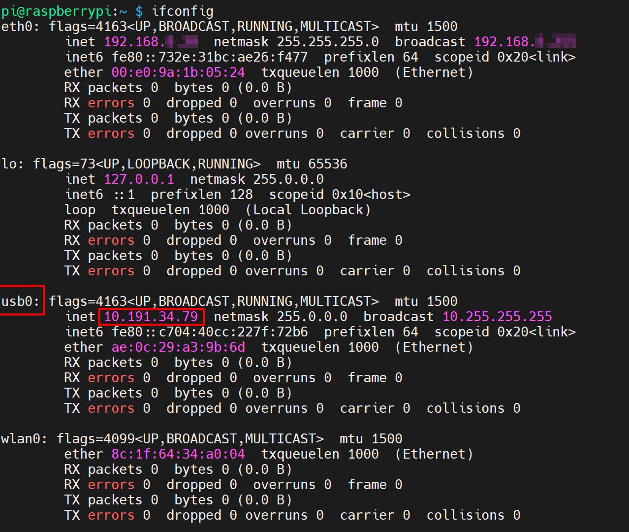
- If the usb0 interface in the returned information displays a specific IP address, it indicates that the 4G network is connected.
- If the usb0 interface in the returned information does not display a specific IP address, it indicates that the 4G network is not connected.
- Execute the following command to query the status of the 4G service.
sudo systemctl status ed-lte-daemon.service
The returned information is as shown in the figure below:
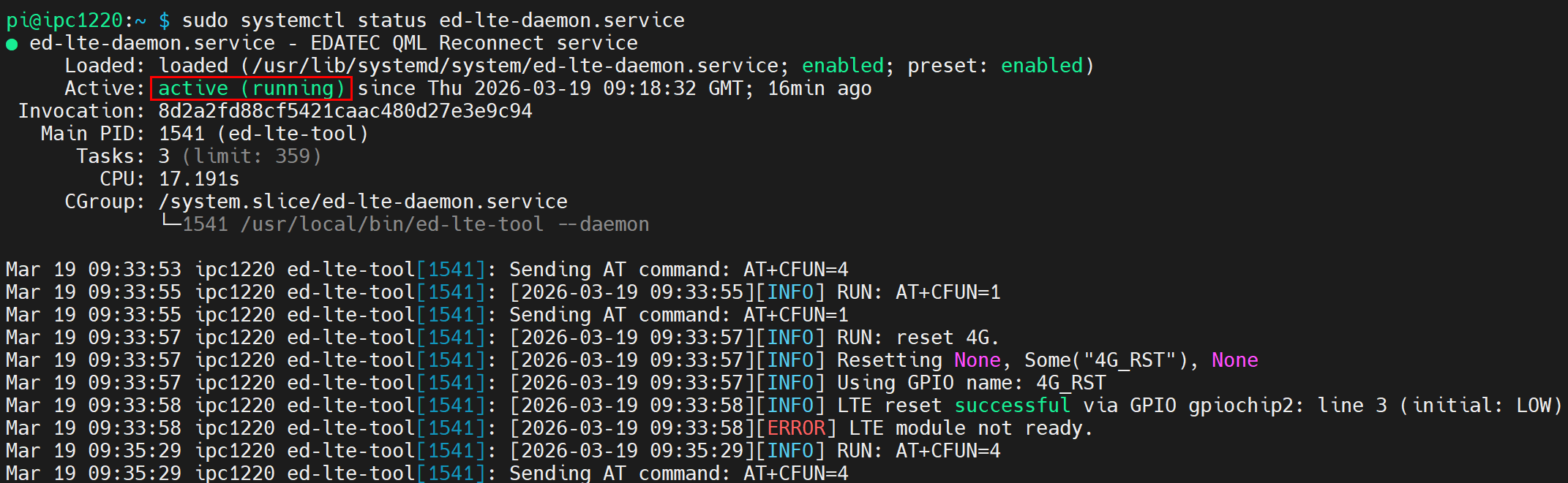
- If the information at the marked position in the returned message shows "Active: active (running)", it indicates that the 4G status is normal.
- If the information at the marked position in the returned message shows "Active: inactive (dead)", it indicates that the 4G status is abnormal.
5.7.2 Scenarios With APN Configuration
If the user's 4G network requires APN configuration, it can be configured by following the steps below.
Preparation:
- The ED-IPC1220 device has started up normally.
- A Nano SIM card with 4G service is correctly installed in the ED-IPC1220's SIM card slot.
- You have obtained the APN name, username, and password. The following uses the example information below.
- APN Name: APN1
- Username: admin
- Password: admin
NOTE
Please turn off the power before inserting or removing the Nano SIM card.
Steps:
- Open a command pane and execute the following commands in sequence to open the
ed-qml.confconfiguration file.
cd /etc/
sudo nano ed-qml.conf
- Set "apn", "apn_user", and "apn_password" in the "APN Config" section as needed.
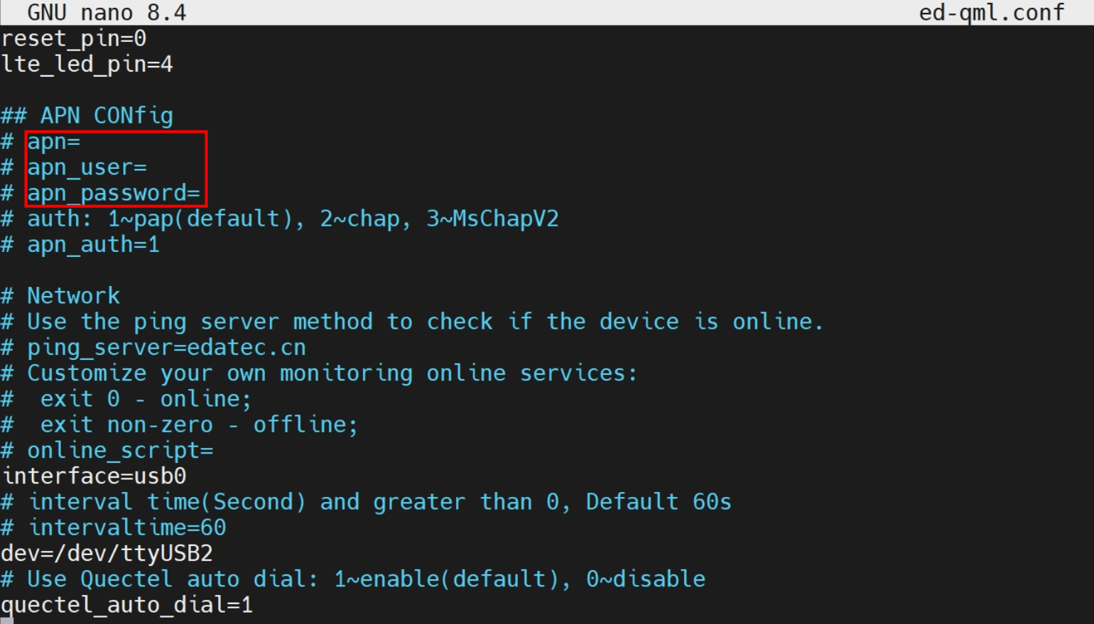
If the ed-qml.conf file does not contain the default configuration example, you can add the following information at the end of the file to customize the APN configuration, "ping_server" in the "Network" section, "online_script", etc.
- APN configuration example:
apn=custom_value
apn_user=custom_value
apn_password=custom_value
auth: 1~pap(default), 2~chap, 3~MsChapV2
apn_auth=1
- Network configuration, default is "edatec.cn".
ping_server=custom_value
- Configure custom script, specify the custom path.
online_script=custom_path
Press
Ctrl+Oto save the file, then pressEnter, and finally pressCtrl+Xto exit the file editing mode.Open a command pane and execute the following command to check if the 4G network is connected.
ifconfig
The return information is as shown below (the usb0 interface represents the 4G interface):
- If the usb0 interface in the returned information displays a specific IP address, it indicates that the 4G network is connected.
- If the usb0 interface in the returned information does not display a specific IP address, it indicates that the 4G network is not connected.
- Execute the following command to query the status of the 4G service.
sudo systemctl status ed-lte-daemon.service
The return information is as shown below:
- If the information at the marked position in the returned message shows "Active: active (running)", it indicates that the 4G status is normal.
- If the information at the marked position in the returned message shows "Active: inactive (dead)", it indicates that the 4G status is abnormal.
5.7.3 Basic Configuration Commands
If the 4G network cannot connect, you can use the following commands for querying and configuration.
| Command | Description |
|---|---|
| ifconfig | Check if the 4G network is connected. The usb0 interface represents the 4G interface, as shown below.
|
| sudo systemctl status ed-lte-daemon.service | Query the status of the 4G service, as shown below.
|
| sudo systemctl enable ed-lte-daemon.service | Enable the 4G service |
| sudo systemctl start ed-lte-daemon.service | Start the 4G service |
| sudo systemctl stop ed-lte-daemon.service | Stop the 4G service |
| sudo ed-lte-tool -r | Reset the 4G module |
TIP
If the 4G port connection is normal but the 4G service status query shows an abnormality, you can enable and then start the 4G service in sequence.
5.8 Configuring RTC
5.9 Configuring Serial Port
Describes the configuration methods for RS485 and RS232.
TIP
Serial port communication supports baud rates from 2400 to 115200.
5.9.1 Installing Picocom Tool
In a Linux environment, you can use the picocom tool to debug the RS232 and RS485 serial ports.
Execute the following command to install the picocom tool.
sudo apt-get install picocom
5.9.2 Configuring RS485
The ED-IPC1220 includes two RS485 interfaces. Their corresponding COM ports and device files are as follows:
| RS485 Port Number | Corresponding COM Port | Corresponding Device File |
|---|---|---|
| 1 | RS485-1 | /dev/com1 |
| 2 | RS485-2 | /dev/com2 |
Preparation:
The connection between the ED-IPC1220's RS485 port and the external device is completed.
Steps:
- (Optional) Disable the serial port login mode.
TIP
- The RS485-1 (GND/A1/B1) port on the ED-IPC1220 device defaults to serial port login mode. If it needs to be configured as a regular serial port, please disable the serial console login mode first.
- The RS485-2 (GND/A2/B2) port defaults to a normal serial port with the serial port login mode disabled, so this step can be skipped.
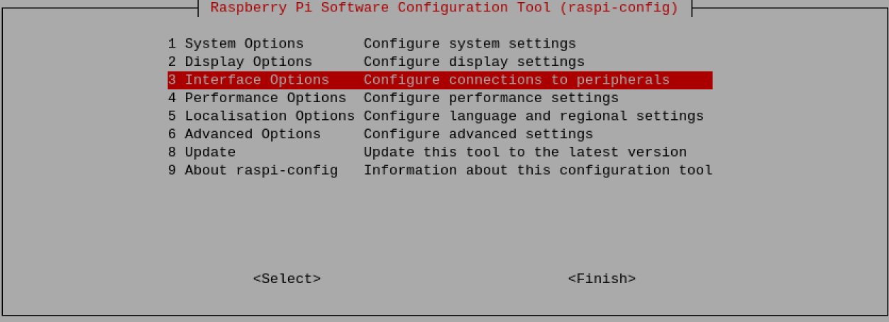
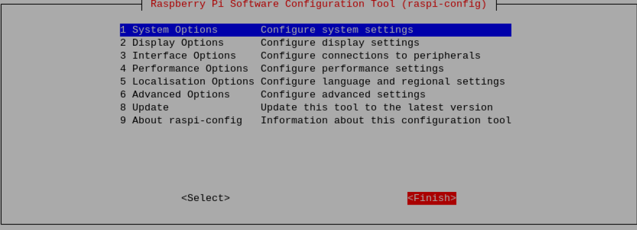
a. Open a command pane and execute the following command to open the configuration tool interface.
sudo raspi-config
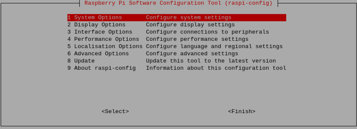
b. Select "Interface Options" from the menu, then press "Enter".
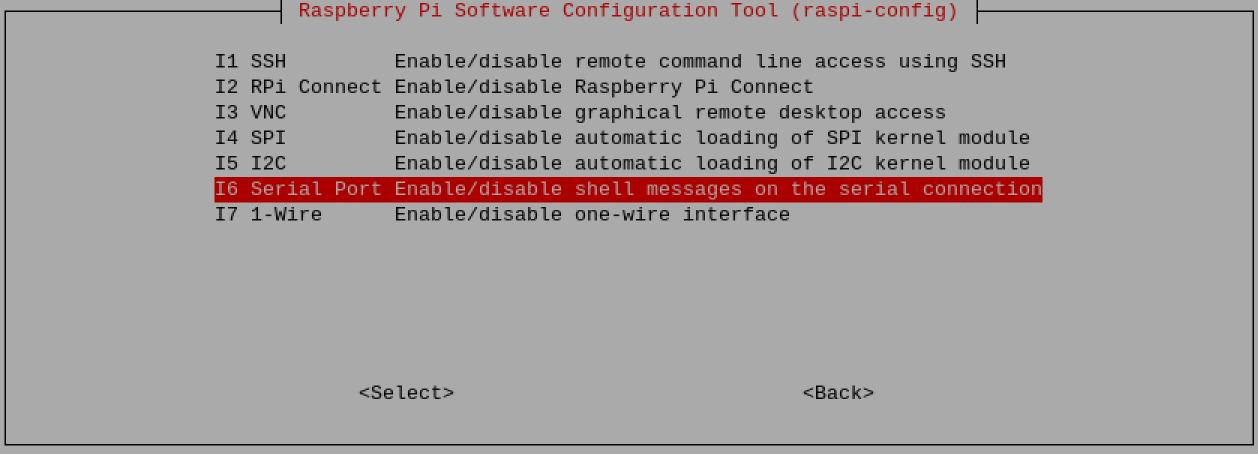
c. Select "Serial Port" from the menu, then press "Enter".
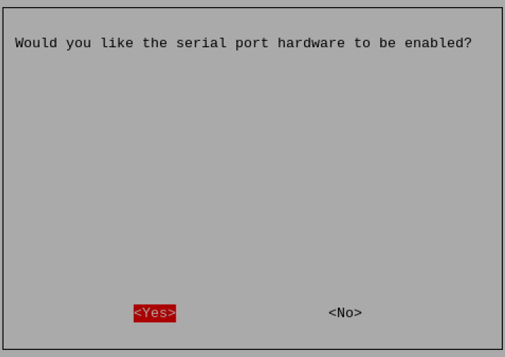
d. Select "No" in the prompt box, then press "Enter".

e. Select "Yes" in the prompt box, then press "Enter".
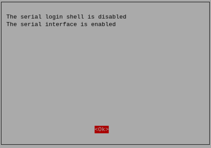
f. Press "Enter" to confirm the settings.
g. Select "Finish" in the configuration tool interface, then press "Enter".
h. Select "Yes" in the prompt box, then press "Enter" to restart the device.

TIP
If the RS485-1 (GND/A1/B1) port needs to be restored to serial console login mode after being disabled, you can reconfigure it in the raspi-config tool.
- Open the serial port and configure the baud rate.
- Execute the following command to open the RS485-1 port and configure the serial baud rate to 115200.
picocom -b 115200 /dev/com1
- Execute the following command to open the RS485-2 port and configure the serial baud rate to 115200.
sudo picocom -b 115200 /dev/com2
- Enter commands as needed to control the external device.
5.9.3 Configuring RS232
The ED-IPC1220 includes one RS232 interface. Its corresponding COM port and device file are as follows:
| RS232 Port Number | Corresponding COM Port | Corresponding Device File |
|---|---|---|
| 1 | RS232 | /dev/com3 |
Preparation:
The connection between the ED-IPC1220's RS232 port and the external device is completed.
Steps:
- Execute the following command to open the RS232 serial port and configure the serial baud rate to 115200.
sudo picocom -b 115200 /dev/com3
- Enter commands as needed to control the external device.
5.10 Configuring DI
The ED-IPC1220 includes 8 DI interfaces. DI0~DI3 are native GPIO ports of the CM0, and DI4~DI7 are extended GPIO ports. The corresponding GPIO ports and names for each DI interface are listed in the table below. Users can configure them according to actual needs.
| DI Interface | Corresponding GPIO of CM0 | Name |
|---|---|---|
| DI0 | GPIO17 | - |
| DI1 | GPIO18 | - |
| DI2 | GPIO19 | - |
| DI3 | GPIO20 | - |
| DI4 | - | DI4 |
| DI5 | - | DI5 |
| DI6 | - | DI6 |
| DI7 | - | DI7 |
Preparation:
The connection between the ED-IPC1220's DI interface and the external sensor is completed.
Steps:
- If the interface is DI0~DI3, execute the following command to obtain the interface data, where X represents the GPIO number corresponding to the DI interface, e.g., 17.
pinctrl get X
A low level (lo) in the returned result indicates an active state.
- If the interface is DI4~DI7, execute the following command to obtain the interface data, where Y represents the name corresponding to the DI interface, e.g., DI4.
sudo ed-gpio get Y
A low level (0) in the returned result indicates an active state.
5.11 Configuring DO
The ED-IPC1220 includes 8 DO interfaces. DO0~DO3 are native GPIO ports of the CM0, and DO4~DO7 are extended GPIO ports. The corresponding GPIO ports and names for each DO interface are listed in the table below. Users can configure them according to actual needs.
| DO Interface | Corresponding GPIO of CM0 | Name |
|---|---|---|
| DO0 | GPIO12 | - |
| DO1 | GPIO21 | - |
| DO2 | GPIO22 | - |
| DO3 | GPIO23 | - |
| DO4 | - | DO4 |
| DO5 | - | DO5 |
| DO6 | - | DO6 |
| DO7 | - | DO7 |
Preparation:
The connection between the ED-IPC1220's DO interface and the external load is completed.
Steps:
- If the interface is DO0~DO3, execute the following commands to set the output to high or low level, where X represents the GPIO number corresponding to the DO interface, e.g., 12.
Set to high level:
pinctrl set X op dh
Set to low level:
pinctrl set X op dl
- If the interface is DO4~DO7, execute the following commands to set the output, where Y represents the name corresponding to the DO interface, e.g., DO4.
Set to high level:
sudo ed-gpio set Y 1
Set to low level:
sudo ed-gpio set Y 0
5.12 Configuring ADC (Optional)
The ED-IPC1220 device includes 2 ADV channels and 2 ADA channels, namely V0, V1, A0, and A1. The default sampling rate for the 4 ADC ports is 1600sps. If you need to use a different sampling rate, you can configure the ADC sampling rate. The detailed configuration steps are described below.
Preparation:
The ED-IPC1220 has been successfully started.
Steps:
- After the device starts normally, open a command window and execute the following command to open the
config.txtconfiguration file.
sudo nano /boot/firmware/config.txt
- In the
[all]section of the configuration file, view the default ADC configuration parameters, as shown in the red box in the figure below.
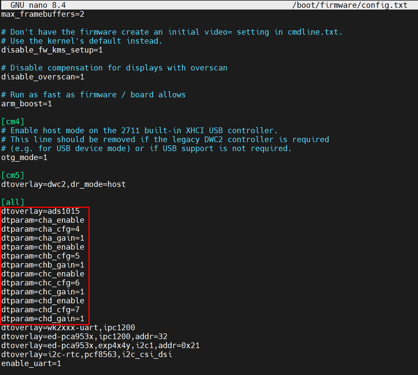
- The default sampling rate is 1600sps, and the parameter is not displayed in the configuration file.
- Add the sampling rate configuration parameters as needed:
dtparam=cha_datarate(V0 channel),dtparam=chb_datarate(V1 channel),dtparam=chc_datarate(A0 channel), anddtparam=chd_datarate(A1 channel).
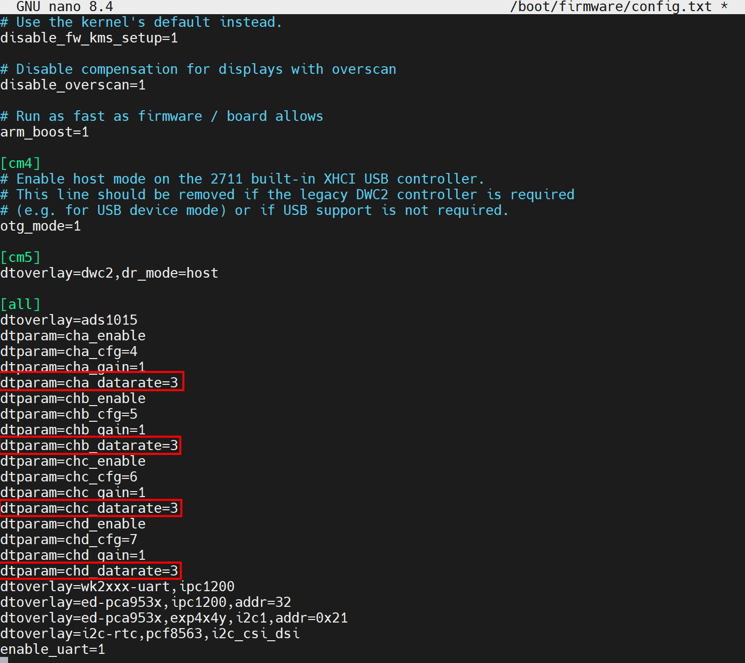
- The sampling rate parameter values include 0, 1, 2, 3, 4, 5, and 6. The corresponding sampling rates are described in the table below.
- As shown in the red box in the figure above, the sampling rate for each of the 4 channels is configured as 920sps.
| Parameter | ADC Channel | Sampling Rate Values |
|---|---|---|
| dtparam=cha_datarate | V0 |
|
| dtparam=chb_datarate | V1 | |
| dtparam=chc_datarate | A0 | |
| dtparam=chd_datarate | A1 |
TIP
Only the sampling rate can be configured. Other parameters cannot be modified and should remain at their default values.
Press
ctrl+oto save the file, then pressEnter, and finally pressctrl+xtoexit the file editing mode.Execute the following command to restart the device and apply the configuration.
sudo reboot
5.13 Configuring USER Indicator
The ED-IPC1220 includes one USER LED. The LED is a dual-color (red/green) LED supporting mixed colors and is controlled via extended I/O. The corresponding extended I/O names are listed in the table below:
| USER LED | GPIO Name |
|---|---|
| Red LED | USER_LED_RED |
| Green LED | USER_LED_GED |
- Query the LED status:
sudo ed-gpio get USER_LED_RED
sudo ed-gpio get USER_LED_GED
- Turn on the red LED:
sudo ed-gpio set USER_LED_RED 1
- Turn off the red LED:
sudo ed-gpio set USER_LED_RED 0
- Turn on the green LED:
sudo ed-gpio set USER_LED_GED 1
- Turn off the green LED:
sudo ed-gpio set USER_LED_GED 0
TIP
The USER LED supports mixing red and green to produce orange.
5.14 Configuring USER Button
The ED-IPC1220 includes one USER button, controlled via GPIO. The corresponding GPIO pin is listed in the table below:
| USER Button | Corresponding GPIO of CM0 |
|---|---|
| USER | GPIO25 |
By default, GPIO25 is at a high level. Pressing the button sets GPIO25 to a low level. You can query the current state using the following command.
pinctrl get 25