1 Hardware Manual
This chapter introduces the product overview, packing list, appearance, button, indicator, and interface.
1.1 Overview
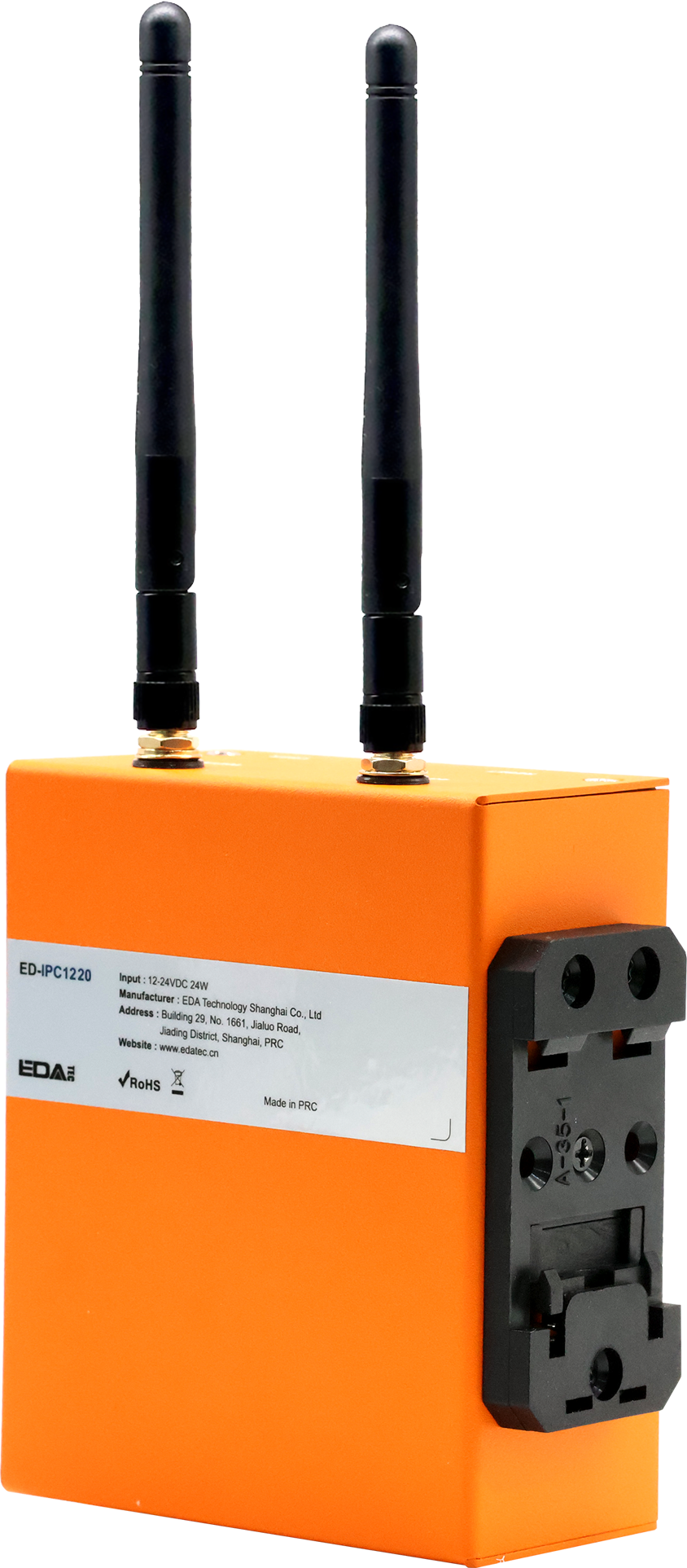
The ED-IPC1220 is an industrial computer based on the Raspberry Pi CM0, featuring 512MB RAM as standard, with optional 8GB or 16GB eMMC. It provides common interfaces such as USB, Ethernet, RS232, RS485, DI/DO, and ADC. It supports network access via Wi-Fi, Ethernet, and 4G, and integrates an RTC. It is primarily used in industrial control and IoT applications.
1.2 Packing List
- 1 x ED-IPC1220 Unit
- [Optional Wi-Fi/BT Version] 1 x 2.4GHz Wi-Fi/BT Antenna
- [Optional 4G Version]1 x 4G Antenna
- 3 x 3-Pin Phoenix Terminals
- 1 x 2-Pin Phoenix Terminal with Screw Holes
- 1 x 6-Pin Phoenix Terminal
- 4 x 5-Pin Phoenix Terminals
1.3 Appearance
Introduce the functions and definitions of the interfaces on each panel.
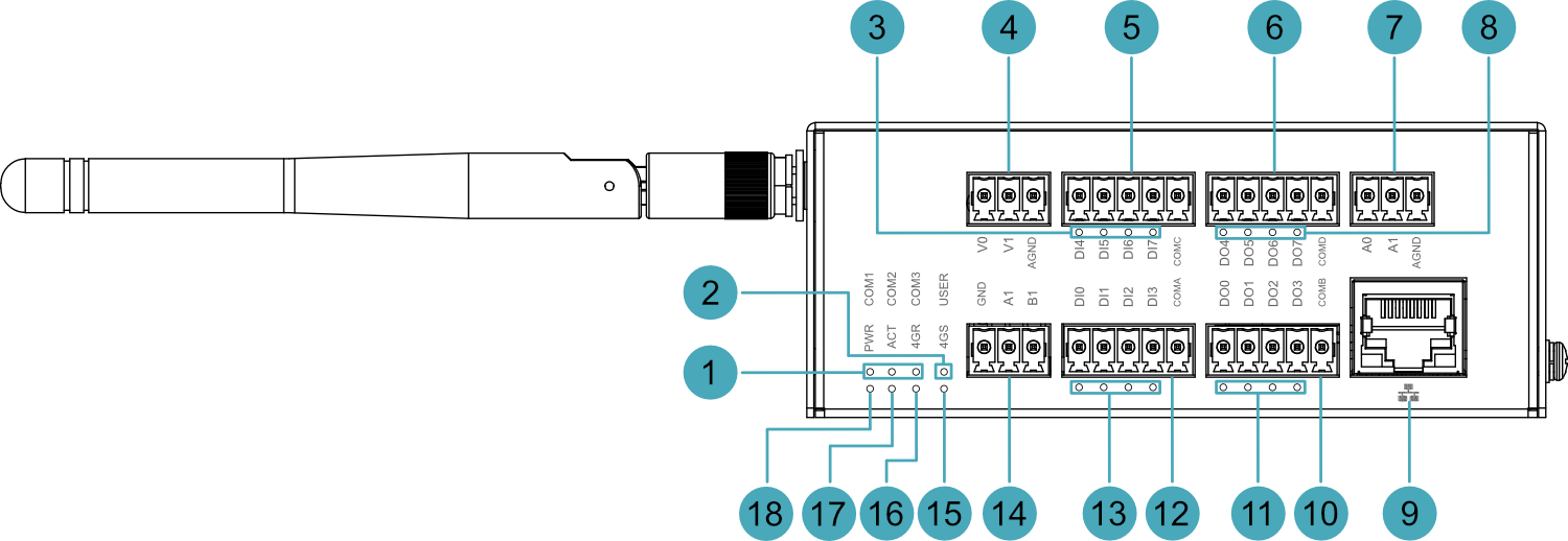
1.3.1 Front Panel
Introduce the types and definitions of the front panel interfaces.
| NO. | Function Definition |
|---|---|
| 1 | 3 x Serial port indicators, green, used to view the communication status of the serial ports.
|
| 2 | 1 x User indicator, green, users can customize its status according to actual needs. |
| 3 | 4 x DI indicators (DI4~DI7), green, used to view the input status of DI ports (DI4~DI7). |
| 4 | 2 x ADV interfaces, 3-Pin 3.5mm pitch Phoenix terminals, for connecting external sensors. |
| 5 | 4 x DI interfaces (DI4~DI7), 5-Pin 3.5mm pitch Phoenix terminals, for connecting external sensors. |
| 6 | 4 x DO interfaces (DO4~DO7), 5-Pin 3.5mm pitch Phoenix terminals, for connecting external loads. |
| 7 | 2 x ADA interfaces, 3-Pin 3.5mm pitch Phoenix terminals, for connecting external sensors. |
| 8 | 4 x DO indicators (DO4~DO7), green, used to view the output status of DO ports (DO4~DO7). |
| 9 | 1 x 100M Ethernet Interface, RJ45 connector, with LED indicator, 10/100M auto-negotiation interface, for connecting to Ethernet. |
| 10 | 4 x DO interfaces (DO0~DO3), 5-Pin 3.5mm pitch Phoenix terminals, for connecting external loads. |
| 11 | 4 x DO indicators (DO0~DO3), green, used to view the output status of DO ports (DO0~DO3). |
| 12 | 4 x DI interfaces (DI0~DI3), 5-Pin 3.5mm pitch Phoenix terminals, for connecting external sensors. |
| 13 | 4 x DI indicators (DI0~DI3), green, used to view the input status of DI ports (DI0~DI3). |
| 14 | 1 x RS485 interface (RS485-1), 3-Pin 3.5mm pitch Phoenix terminal, for connecting third-party controllers. |
| 15 | 1 x 4G Signal indicator, red/green dual-color, used to view the status of the 4G signal. |
| 16 | 1 x 4G Network registration indicator, red/green dual-color, used to view the network registration status of the 4G module. |
| 17 | 1 x System status indicator, green, used to view the system's read/write data status. |
| 18 | 1 x Power indicator, red, used to view the device's power status. |
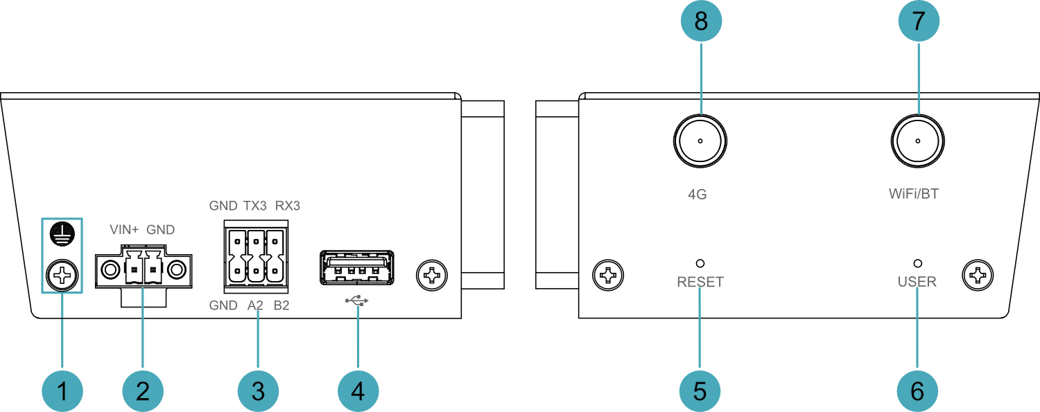
1.3.2 Rear Panel
Introduces the interface types and definitions on the rear panel.

| NO. | Function Definition |
|---|---|
| 1 | 1 x Rail mounting bracket, used to install the ED-IPC1220 unit on a DIN rail via the bracket. |
| 2 | 1 x Nano SIM card slot (optional) for installing a Nano SIM card to obtain 4G signal. |
| 3 | 1 x Type-C USB interface, supports eMMC flashing via this interface. |
1.3.3 Side Panel
Introducing the types and definitions of side panel interfaces.
| NO. | Function Definition |
|---|---|
| 1 | 1 x Grounding point, for connecting to the earth ground of the external power supply. |
| 2 | 1 x DC input, 2-Pin 3.5mm pitch Phoenix terminal with screw holes, supports 9V~28V power input. |
| 3 | 1 x RS485 interface (RS485-2) + 1 x RS232 Interface, 2x3-Pin 3.5mm pitch phoenix terminal, for connecting third-party controllers. |
| 4 | 1 x USB 2.0 interface, Type-A connector, supports up to 480Mbps transmission rate. |
| 5 | 1 x Reset Button, recessed button, pressing the button restarts the device. |
| 6 | 1 x User Button, recessed button, users can customize its action according to actual needs. |
| 7 | 1 x Wi-Fi/BT antenna interface (optional), SMA connector, for connecting the Wi-Fi/BT antenna. |
| 8 | 1 x 4G antenna interface (optional), SMA connector, for connecting the 4G antenna. |
1.4 Button
The ED-IPC1220 device contains 2 recessed buttons, namely the RESET button and the USER button, marked as "RESET" and "USER" on the housing.
- RESET Button: Pressing the RESET button resets the device, causing it to restart.
- USER Button: A user-defined button. No action is configured by default. The corresponding GPIO pin is GPIO25, supporting user-defined actions.
1.5 Indicator
Introduces the various states and meanings of the indicators on the ED-IPC1220 device.
| Indicator | Status | Description |
|---|---|---|
| PWR | On | The device has been powered on. |
| Blink | Power supply of the device is abnormal, please stop the power supply immediately. | |
| Off | The device is not powered on. | |
| ACT | Blink | The system started successfully and is reading and writing data. |
| Off | The device is not powered on or does not read and write data. | |
| USER | On | User-defined |
| Off | The device is not powered on or is not user-defined. The default state is off. | |
| 4GR | Red Steady On | SIM card failure |
| Red Slow Blink | 4G module initializing | |
| Red Fast Blink | 4G module disconnected from network | |
| Green Steady On | 4G module successfully registered to network | |
| Green Slow Blink | 4G module data traffic normal | |
| Off | 4G module not working | |
| 4GS | Red Steady On | 4G module has no signal |
| Green Steady On | 4G module signal normal | |
| Red/Green Dual-color Steady On | 4G module signal abnormal | |
| Off | 4G module not working | |
| Green indicator of Ethernet port | On | The Ethernet connection is abnormal |
| Blink | Data is being transmitted over the Ethernet port | |
| Off | The Ethernet connection is not set up | |
| Yellow indicatorof Ethernet port | On | The Ethernet connection is in the normal state |
| Blink | The Ethernet connection is abnormal | |
| Off | The Ethernet connection is not set up | |
| COM1~COM3 | On/Blink | Data is being transmitted |
| Off | The device is not powered on or there is no data transmission | |
| DI0~DI7 | On/Blink | Input signal detected |
| Off | Device not powered on or no data transmission | |
| DO0~DO7 | On/Blink | Output signal detected |
| Off | Device not powered on or no data transmission |
1.6 Interface
Introduce the definitions and functions of the various interfaces in the product.
1.6.1 Nano SIM Card Slot (Optional)
The ED-IPC1220 device contains 1 Nano SIM card slot. The slot interface is marked with " ", used for installing a Nano SIM card to obtain 4G signal.
TIP
If the customer's selected product does not include the 4G function, the device will not include the Nano SIM card slot.
1.6.2 Power Interface
The ED-IPC1220 device contains 1 power input interface, using a 2-Pin 3.5mm pitch Phoenix terminal with screw holes. The interface is marked as "VIN+/GND" and supports 9V~28V power input.
1.6.3 RS485/RS232 Interface
The ED-IPC1220 device contains 2 RS485 interfaces and 1 RS232 interface, using one 3-Pin 3.5mm pitch Phoenix terminal (1 x RS485) and one 2x3-Pin 3.5mm pitch Phoenix terminal (1 x RS485 + 1 x RS232). The interfaces are marked as "GND/A1/B1", "GND/A2/B2", and "GND/TX3/RX3" respectively, supporting connection to third-party controllers.
1.6.3.1 3-Pin 3.5mm Pitch Phoenix Terminal (1 x RS485)
The terminal pin definitions are as follows:
 | Pin ID | Pin Name |
|---|---|---|
| 1 | GND | |
| 2 | A1(RS485-1_A) | |
| 3 | B1(RS485-1_B) |
The corresponding CM0 GPIO pin names for the RS485 interface are as follows:
| Signal | CM0 GPIO Name |
|---|---|
| RS485-1_A | GPIO14 |
| RS485-1_B | GPIO15 |
1.6.3.2 2x3-Pin 3.5mm Pitch Phoenix Terminal (1 x RS485 + 1 x RS232)
The terminal pin definitions are as follows:
 | Pin ID | Pin Name |
|---|---|---|
| 1 | GND | |
| 2 | A2(RS485-2_A) | |
| 3 | B2(RS485-2_B) | |
| 4 | GND | |
| 5 | TX3 | |
| 6 | RX3 |
The corresponding SPI pin names for the RS485 and RS232 interfaces are as follows:
| Signal | SPI Pin Out |
|---|---|
| RS485-2_A | TX1 |
| RS485-2_B | RX1 |
| TX3 | TX2 |
| RX3 | RX2 |
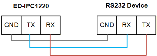
1.6.3.3 Connecting Cables
The RS232 connection diagram is as follows:
The RS485 connection diagram is as follows:
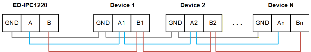
RS485 Termination Resistor Configuration
The ED-IPC1220 device contains 2 RS485 interfaces. A 120Ω termination resistor is reserved between lines A and B on the RS485 circuit. Inserting a jumper cap enables this termination resistor. By default, no jumper cap is connected, and the 120Ω termination resistor function is disabled. The locations of the termination resistors on the PCBA are J11 (for RS485-1) and J13 (for RS485-2).
TIP
The device housing needs to be opened to view the location of the 120Ω termination resistors.
1.6.4 DI Interface
The ED-IPC1220 device contains 8 DI interfaces, using two 5-Pin 3.5mm pitch Phoenix terminals, supporting connection to external sensors.
The terminal pin definitions are as follows:
 | Pin ID | Pin Name |
| 1 | DI0 | |
| 2 | DI1 | |
| 3 | DI2 | |
| 4 | DI3 | |
| 5 | COMA | |
| 6 | DI4 | |
| 7 | DI5 | |
| 8 | DI6 | |
| 9 | DI7 | |
| 10 | COMC |
Connecting Cables
The connection diagram for a single DI interface is as follows:

| Parameter | Description |
|---|---|
| Input Type | Wet Contact (NPN) |
| Isolation Protection | 3.75kV |
| COM Terminal | Every 4 DI channels share one common COM terminal
|
| DI to COM |
|
1.6.5 DO Interface
The ED-IPC1220 device contains 8 DO interfaces, using two 5-Pin 3.5mm pitch Phoenix terminals, supporting connection to external loads.
The terminal pin definitions are as follows:
 | Pin ID | Pin Name |
| 1 | DO0 | |
| 2 | DO1 | |
| 3 | DO2 | |
| 4 | DO3 | |
| 5 | COMB | |
| 6 | DO4 | |
| 7 | DO5 | |
| 8 | DO6 | |
| 9 | DO7 | |
| 10 | COMD |
Connecting Cables
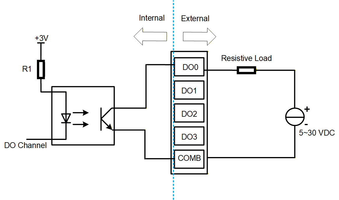
The connection diagram for a single DO interface is as follows:
| Parameter | Description |
|---|---|
| Sensor Type | NPN |
| Isolation Protection | 3.75kV |
| COM Terminal | Every 4 DO channels share one common COM terminal:
|
| Output | 5~30 VDC, 24 VDC recommended, maximum current 0.2A (per channel) |
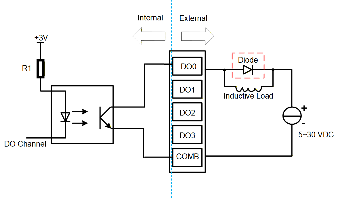
WARNING
If an inductive load is connected to a DO channel, it is recommended to add a freewheeling diode (as shown below) to the circuit for protection. Please select an appropriate freewheeling diode according to the specifications of the inductive load.
1.6.6 ADV Interface
The ED-IPC1220 device contains 2 Analog Voltage Input (ADV) interfaces, using 3-Pin 3.5mm pitch Phoenix terminals, supporting connection to external sensors.
The terminal pin definitions are as follows:
 | Pin ID | Pin Name |
| 1 | V0 | |
| 2 | V1 | |
| 3 | AGND |
Connecting Cables
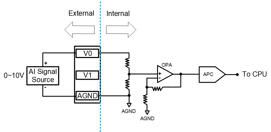
The connection diagram for a single ADV interface is as follows:
| Parameter | Description |
|---|---|
| Signal Type | Voltage Input (Differential) |
| Input Voltage Range | 0~10V |
| Input Impedance | 10MΩ |
| Resolution | 12 bit |
| Accuracy | ±0.1% of full scale at 25°C; ±0.3% of full scale from -20°C to 60°C |
| Sampling Rate | 3KHz |
1.6.7 ADA Interface
The ED-IPC1220 device contains 2 Analog Current Input (ADA) interfaces, using 3-Pin 3.5mm pitch Phoenix terminals, supporting connection to external sensors.
The terminal pin definitions are as follows:
 | Pin ID | Pin Name |
| 1 | A0 | |
| 2 | A1 | |
| 3 | AGND |
Connecting Cables
The connection diagram for a single ADA interface is as follows:
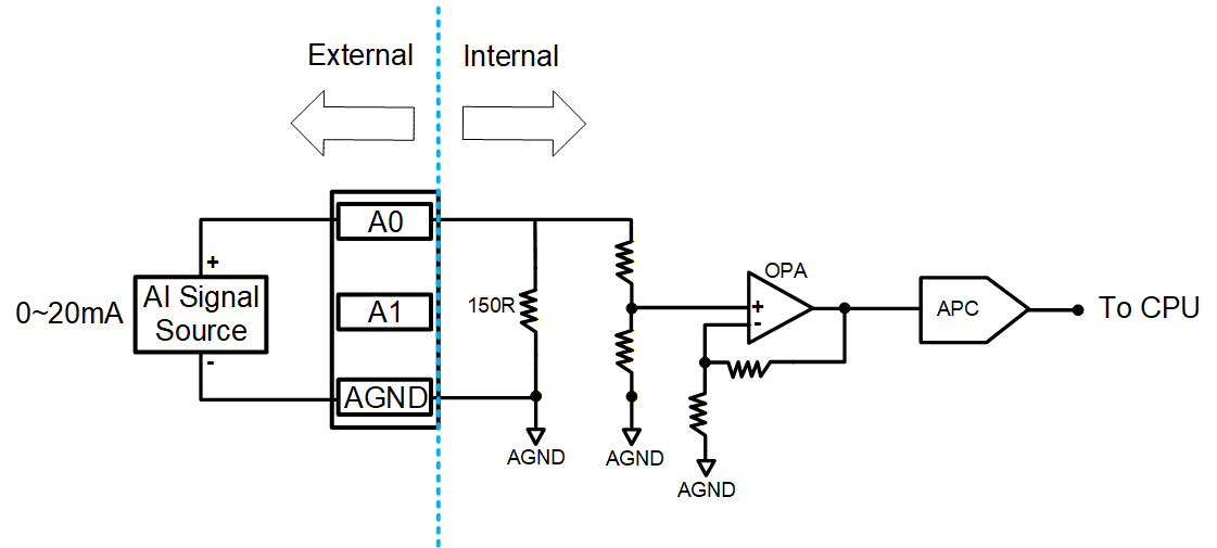
| Parameter | Description |
|---|---|
| Signal Type | Current Input (Differential) |
| Input Current Range | 0~20mA |
| Current Sampling Resistor | 120Ω |
| Input Impedance | 10MΩ |
| Resolution | 12 bit |
| Accuracy | ±0.1% of full scale at 25°C; ±0.3% of full scale from -20°C to 60°C |
| Sampling Rate | 3KHz |
1.6.8 100M Ethernet Interface
The ED-IPC1220 device contains 1 auto-negotiating 10/100M Ethernet interface, marked with " ". It uses an RJ45 connector. When connecting to Ethernet, it is recommended to use a Cat6 or higher specification network cable. The corresponding pin definitions for the connector are as follows:
 | Pin ID | Pin Name |
|---|---|---|
| 1 | TX+ | |
| 2 | TX- | |
| 3 | Rx+ | |
| 4 | - | |
| 5 | - | |
| 6 | RX- | |
| 7 | - | |
| 8 | - |
1.6.9 USB 2.0 Interface
The ED-IPC1220 device contains 1 USB 2.0 interface, marked with " ", a standard Type-A interface. It supports connecting standard USB 2.0 peripherals, with a maximum transmission rate of 480Mbps.
1.6.10 Type-C USB Interface
The ED-IPC1220 device contains 1 Type-C USB interface, marked as "PROGRAMMING". It supports programming the device's eMMC by connecting to a PC.
1.6.11 Antenna Interface (Optional)
The ED-IPC1220 device contains 2 SMA antenna interfaces, marked as "4G" and "WiFi/BT" respectively, for connecting the 4G antenna and the Wi-Fi/BT antenna.
TIP
If the customer's selected product does not include the 4G function and Wi-Fi function, the device will not include the antenna interfaces.