
1 Hardware Manual
This chapter introduces the product overview, package contents, appearance, buttons, indicators, and interfaces.
1.1 Overview
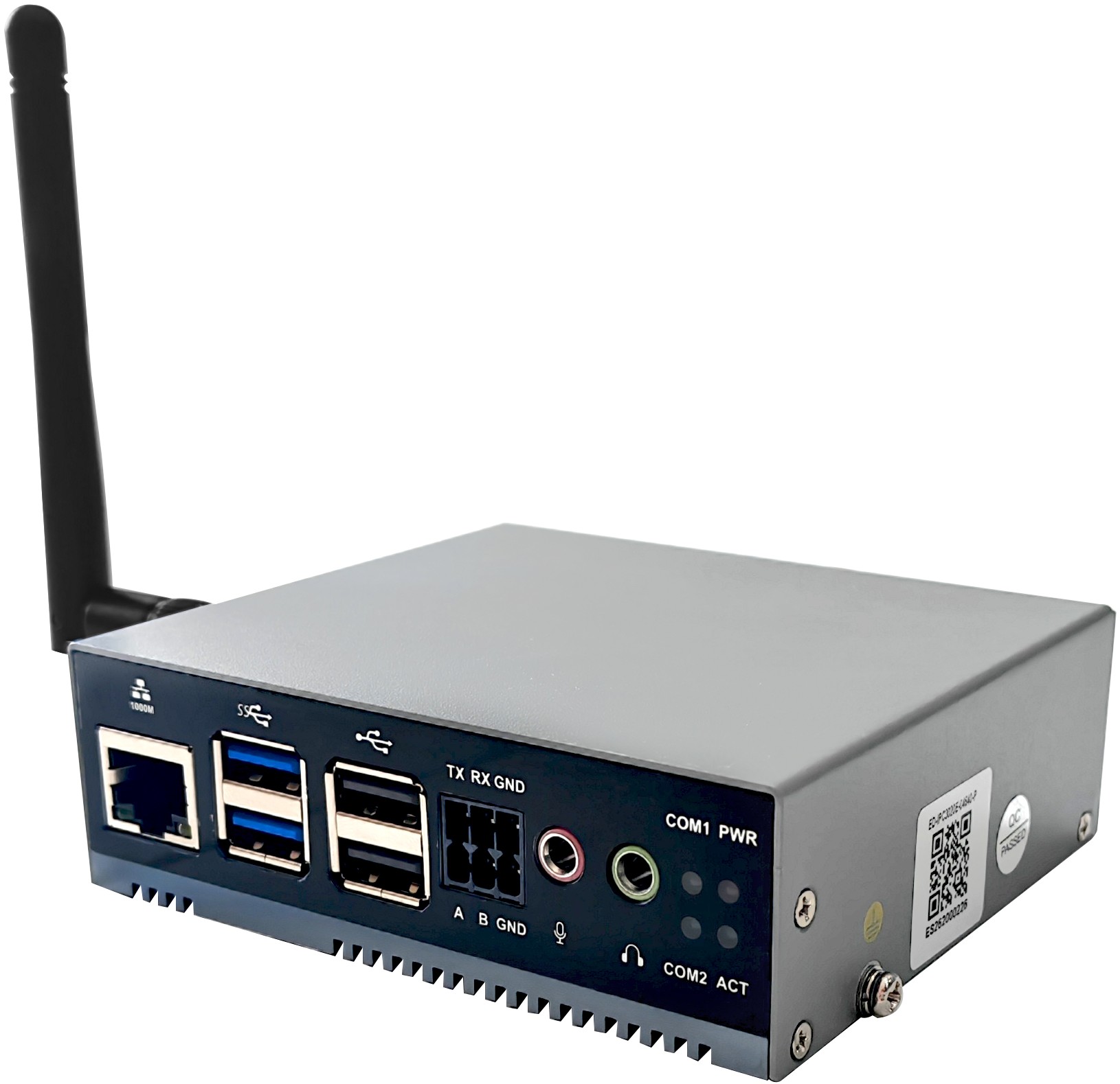
The ED-IPC3020E is an industrial computer based on the Raspberry Pi 5 with an external antenna. Depending on different application scenarios and user requirements, computer systems with various specifications of RAM, SD card, and SSD can be selected.
- Optional RAM specifications include 1GB, 2GB, 4GB, 8GB, and 16GB.
- Optional SD card specifications include 32GB and 64GB.
- Optional SSD specifications include 128GB and 256GB.
The ED-IPC3020E provides HDMI, USB 2.0, USB 3.0, Ethernet, RS232, RS485, and Audio interfaces, supports network access via Wi-Fi and Ethernet; integrates an RTC, and is mainly used in industrial control and IoT fields.
1.2 Package Contents
- 1 x ED-IPC3020E Unit
- 1 x Wi-Fi/BT Antenna
- 1 x 6-Pin Phoenix Terminal
- 1 x Tweezers (for inserting and removing the SD card)
1.3 Appearance
Introduces the functions and definitions of the interfaces on each panel.
1.3.1 Front Panel
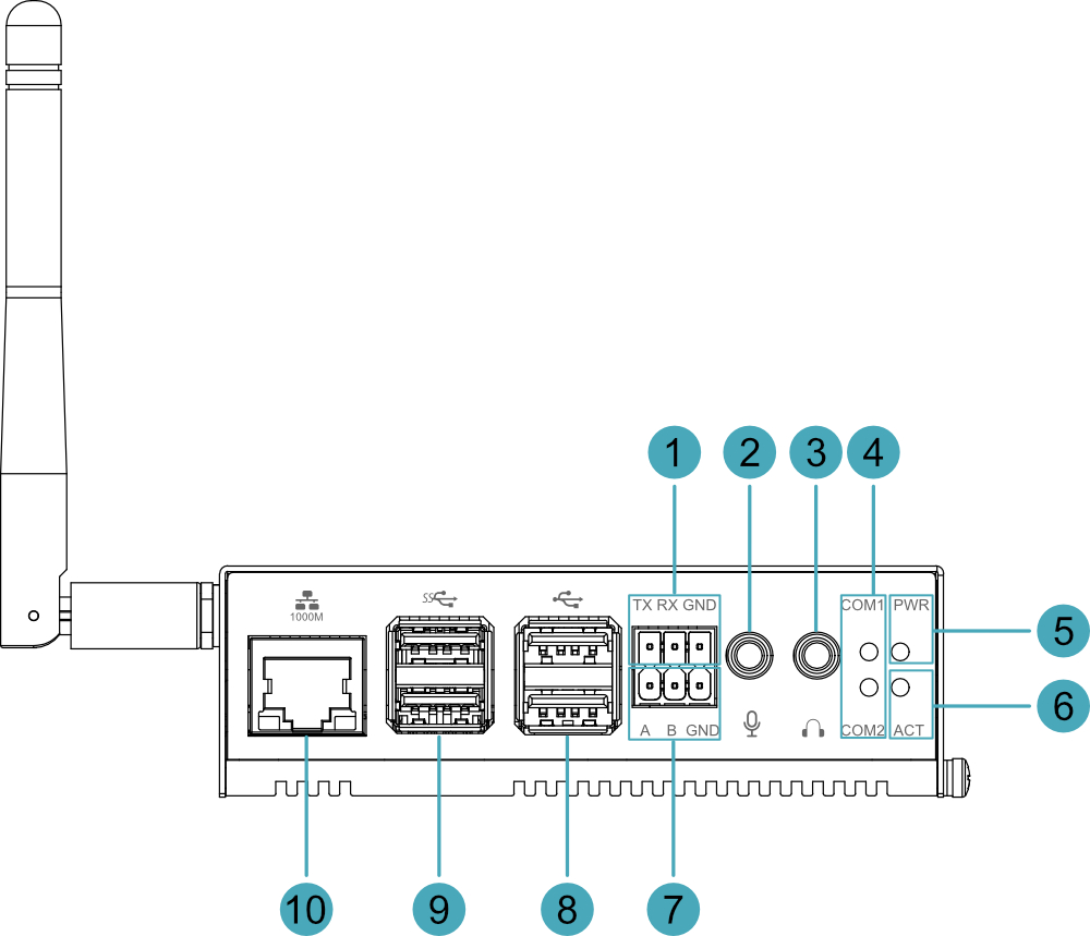
Introduces the functions and definitions of the front panel.
| No. | Function Definition |
|---|---|
| 1 | 1 x RS232 interface, 3-Pin 3.5mm pitch Phoenix terminal, used for connecting third-party control devices. |
| 2 | 1 x Audio input interface (LINE IN), red 3.5mm audio jack, supports stereo input. |
| 3 | 1 x Audio output interface (HPO), green 3.5mm audio jack, stereo output. |
| 4 | 2 x Serial port indicators, green, used to view the communication status of the serial ports. |
| 5 | 1 x Power indicator, red, used to view the power-on status of the device. |
| 6 | 1 x System status indicator, green, used to view the data read/write status of the system. |
| 7 | 1 x RS485 interface, 3-Pin 3.5mm pitch Phoenix terminal, used for connecting third-party control devices. |
| 8 | 2 x USB 2.0 interfaces, Type-A connector, each supporting a maximum transfer rate of 480Mbps. |
| 9 | 2 x USB 3.0 interfaces, Type-A connector, each supporting a maximum transfer rate of 5Gbps. |
| 10 | 1 x Ethernet interface (10/100/1000M auto-negotiation), RJ45 connector, used for accessing Ethernet. |
1.3.2 Rear Panel
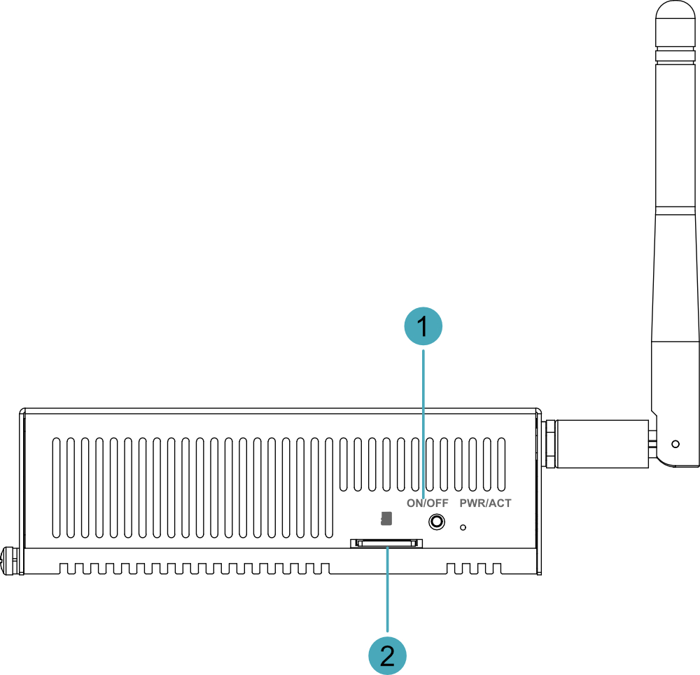
Introduces the types and definitions of the rear panel interfaces.
| No. | Function Definition |
|---|---|
| 1 | 1 x ON/OFF button, used to power on and power off the device. |
| 2 | 1 x Micro SD card slot, used for installing a Micro SD card, supports booting the system from the SD card. |
1.3.3 Side Panel
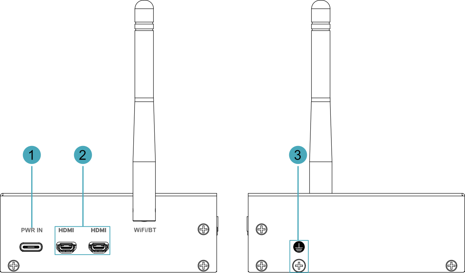
Introduces the types and definitions of the side panel interfaces.
| No. | Function Definition |
|---|---|
| 1 | 1 x USB Type-C interface, supports 5V power input. |
| 2 | 2 x HDMI interfaces, Micro HDMI connector, resolution supports 4K 60Hz. |
| 3 | 1 x Grounding point, connects to the earth ground of the external power supply. |
1.4 Button
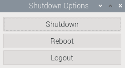
The ED-IPC3020E device includes 1 ON/OFF button, silk-screened as "ON/OFF" on the casing. In the Desktop system, press the button briefly to open the shutdown options menu, where you can choose to shutdown, Reboot, or Logout.
TIP
- In the Desktop system, quickly press the ON/OFF button twice consecutively to shut down the device directly.
- After shutting down the device by pressing the ON/OFF button twice consecutively, press the ON/OFF button once briefly to power on the device.
1.5 Indicator
Introduces the various states and meanings of the indicators included in the ED-IPC3020E device.
| Indicator | Status | Description |
|---|---|---|
| PWR | Solid On | Device is powered on |
| Blinking | Device power anomaly, stop supplying power immediately | |
| Off | Device is not powered on | |
| ACT | Blinking | System boot successful and reading/writing data |
| Off | Device is not powered on or not reading/writing data | |
| COM1~COM2 | Solid On/Blinking | Data is being transmitted |
| Off | Device is not powered on or no data transmission | |
| Yellow indicator of Ethernet port | Solid On | The Ethernet connection is in the normal state. |
| Blinking | The Ethernet connection is abnormal. | |
| Off | The Ethernet connection is not set up. | |
| Green indicator of Ethernet port | Solid On | The data transmission is abnormal. |
| Blinking | Data is being transmitted over the Ethernet port. | |
| Off | The Ethernet connection is not set up. |
TIP
The functions of the PWR/ACT indicators native to the Raspberry Pi 5 are already transferred to the separate PWR and ACT indicators by default, so the PWR/ACT indicators remain solidly lit after the device is powered on.
1.6 Interface
Introduces the definitions and functions of each interface in the product.
1.6.1 Micro SD Card
The ED-IPC3020E device includes 1 Micro SD card slot, silk-screened as “ ” on the casing, supports installing a Micro SD card, used for booting the system.
1.6.2 Power Interface
The ED-IPC3020E device includes 1 power input interface, using a Type-C USB connector, the interface is silk-screened as "PWR IN", supports 5V power input.
TIP
To achieve better performance for the Raspberry Pi 5, it is recommended to use the Raspberry Pi 27W USB-C adapter.
1.6.3 1000M Ethernet Interface
The ED-IPC3020E device includes 1 auto-negotiating 10/100/1000M Ethernet interface, RJ45 connector with LED indicators, the interface is silk-screened as “ ”, used for accessing Ethernet.
1.6.4 HDMI Interface
The ED-IPC3020E device includes 2 HDMI interfaces, using Micro HDMI connectors, the interface is silk-screened as "HDMI". Used for connecting an HDMI monitor, supports up to 4Kp60 video output.
TIP
Some Micro HDMI cables have shorter Micro HDMI connectors, which may cause HDMI connection issues. Therefore, it is recommended to use the official Raspberry Pi Micro HDMI to Standard HDMI cable.
1.6.5 USB 2.0 Interface
The ED-IPC3020E device includes 2 USB 2.0 interfaces, standard Type-A connectors, the interface is silk-screened as “ ”, supports connecting standard USB 2.0 peripherals, each supporting a maximum transfer rate of 480Mbps.
1.6.6 USB 3.0 Interface
The ED-IPC3020E device includes 2 USB 3.0 interfaces, standard Type-A connectors, the interface is silk-screened as “ ”, supports connecting standard USB 3.0 peripherals, each supporting a maximum transfer rate of 5Gbps.
1.6.7 RS232 Interface
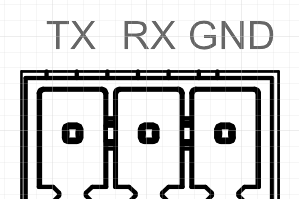
ED-IPC3020E device includes 1 RS232 interface, 3-Pin 3.5mm pitch Phoenix terminal, the interface is silk-screened as "TX/RX/GND".
Pin Definitions
Terminal pin definitions are as follows:
 | Pin | Definition |
|---|---|---|
| 1 | TX | |
| 2 | RX | |
| 3 | GND |
The corresponding Pi5 pin names for the RS232 interface are as follows:
| Signal | GPIO | Definition |
|---|---|---|
| TX | GPIO4 | UART3_TXD |
| RX | GPIO5 | UART3_RXD |
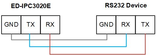
Connecting Cables
The wiring diagram for the RS232 serial port is as follows:
1.6.8 RS485 Interface
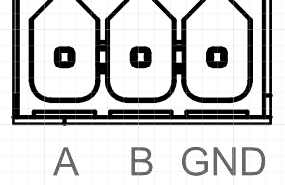
The ED-IPC3020E device includes 1 RS485 interface, 3-Pin 3.5mm pitch Phoenix terminal, the interface is silk-screened as "A/B/GND".
Pin Definitions
Terminal pin definitions are as follows:
 | Pin | Definition |
|---|---|---|
| 1 | A | |
| 2 | B | |
| 3 | GND |
The corresponding Pi5 pin names for the RS485 interface are as follows:
| Signal | GPIO | Definition |
|---|---|---|
| A | GPIO12 | UART5_TXD |
| B | GPIO13 | UART5_RXD |
Connecting Cables
The wiring diagram for the RS485 serial port is as follows:

RS485 Termination Resistor Configuration
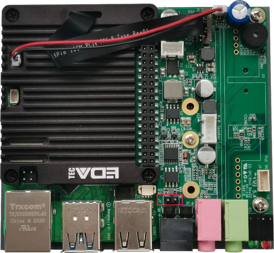
The ED-IPC3020E device includes 1 RS485 interface. A 120R jumper resistor is reserved between A and B of the RS485 line. Inserting a jumper cap enables this termination resistor. By default, the jumper cap is not connected, and the 120R termination resistor function is disabled. The location of the jumper resistor on the PCBA is J7 (position shown in the red box).
TIP
You need to open the device casing to view the position of the 120R jumper resistor.
1.6.9 Audio Input Interface
The ED-IPC3020E device includes 1 audio input interface (LINE IN), red 3.5mm audio jack, the interface is silk-screened as “ ”, supports stereo input.
1.6.10 Audio Output Interface
The ED-IPC3020E device includes 1 audio output interface (HPO), green 3.5mm audio jack, the interface is silk-screened as " ", supports stereo output.
1.6.11 Internal Interfaces
Introduces the internal reserved interfaces of the ED-IPC3020E device. These interfaces can only be accessed after opening the device casing and can be expanded according to actual needs.
TIP
You need to open the device casing to view the internal interfaces.
1.6.11.1 40-Pin GPIO Header
ED-IPC3020E device internally includes 1 40-PIN GPIO header, pin definitions are as follows:
| Pin | Definition | Pin | Definition |
|---|---|---|---|
| 1 | 3.3V (Assigned) | 2 | 5V |
| 3 | Pi5_SDA1 (Assigned) | 4 | 5V |
| 5 | Pi5_SCL1 (Assigned) | 6 | GND |
| 7 | Pi5_TXD3 (Assigned) | 8 | GPIO14 |
| 9 | GND | 10 | GPIO15 |
| 11 | TP_INT | 12 | PCM_CLK (Assigned) |
| 13 | GPIO27 | 14 | GND |
| 15 | GPIO22 | 16 | GPIO23 |
| 17 | 3.3V | 18 | GPIO24 |
| 19 | GPIO10 | 20 | GND |
| 21 | GPIO9 | 22 | GPIO25 |
| 23 | GPIO11 | 24 | GPIO8 |
| 25 | GND | 26 | GPIO7 |
| 27 | ID_SDA | 28 | ID_SCL |
| 29 | Pi5_RXD3 (Assigned) | 30 | GND |
| 31 | Buzzer_EN (Assigned) | 32 | Pi5_TXD5 (Assigned) |
| 33 | Pi5_RXD5 (Assigned) | 34 | GND |
| 35 | PCM_FS (Assigned) | 36 | Pi5_SD_ACT_L (Assigned) |
| 37 | GPIO26 | 38 | PCM_DIN (Assigned) |
| 39 | GND | 40 | PCM_DOUT (Assigned) |
1.6.11.2 M.2 M Key Interface
The ED-IPC3020E device internally contains 1 M.2 M Key connector, used for connecting an external SSD. It is compatible with M.2 2230, M.2 2242, and M.2 2260 form factor SSDs and supports optional SSDs with different memory capacities.
1.6.11.3 RTC Battery Base
The ED-IPC3020E device internally contains 1 CR1220 RTC battery base. No CR1220 battery is included as standard from the factory. Users can purchase one as needed.
TIP
The ED-IPC3020E has an integrated 1F supercapacitor serving as an RTC backup power source, providing short-term power failure protection. If there is a requirement for long-period power-off data retention, users can purchase and install a CR1220 battery themselves.