
1 Quick Start Guide
This chapter provides an overview of the Modbus TCP coupler, including networking, wiring, network configuration, other parameter settings, and I/O module settings.
1.1 Overview
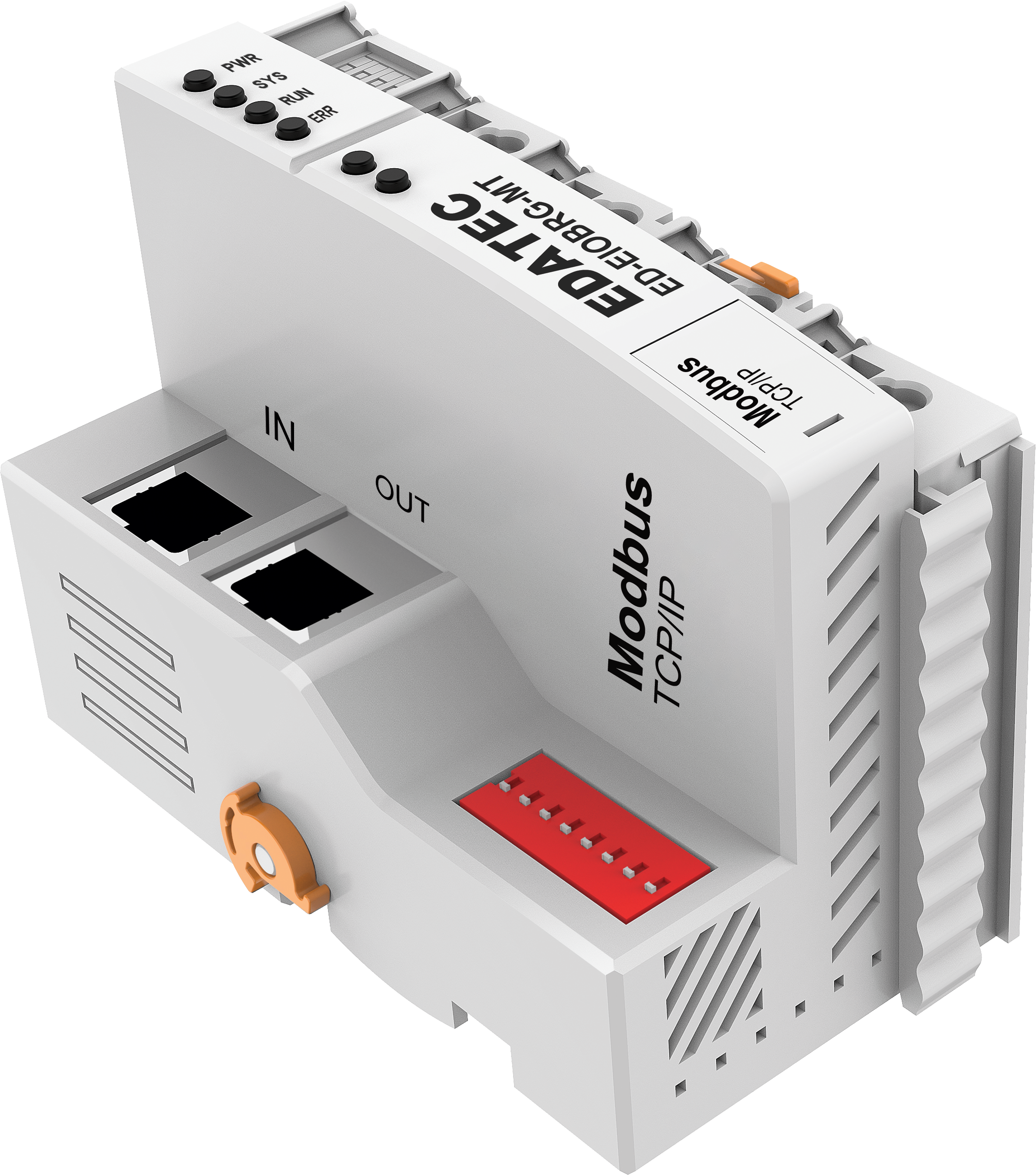
The ED-EIOBRG-MT is a Modbus TCP coupler primarily used to seamlessly integrate slave devices employing different fieldbus protocols (such as Profibus DP, CANopen, DeviceNet, etc.) into a standard Modbus TCP Ethernet network. It acts as a protocol conversion gateway, enabling a host computer (PLC, SCADA, HMI) to access data from heterogeneous bus devices on the lower layer through a unified Modbus TCP interface.
The maximum transmission distance of the ED-EIOBRG-MT is 100m, and it supports expanding up to 32 I/O modules. As a connection node, it can connect multiple Modbus TCP slave devices to a Modbus TCP network, meeting the requirements of various application scenarios.
1.1.1 Interface
The ED-EIOBRG-MT features 2 100M Ethernet ports and 8 PT terminals, as shown in the figure below.
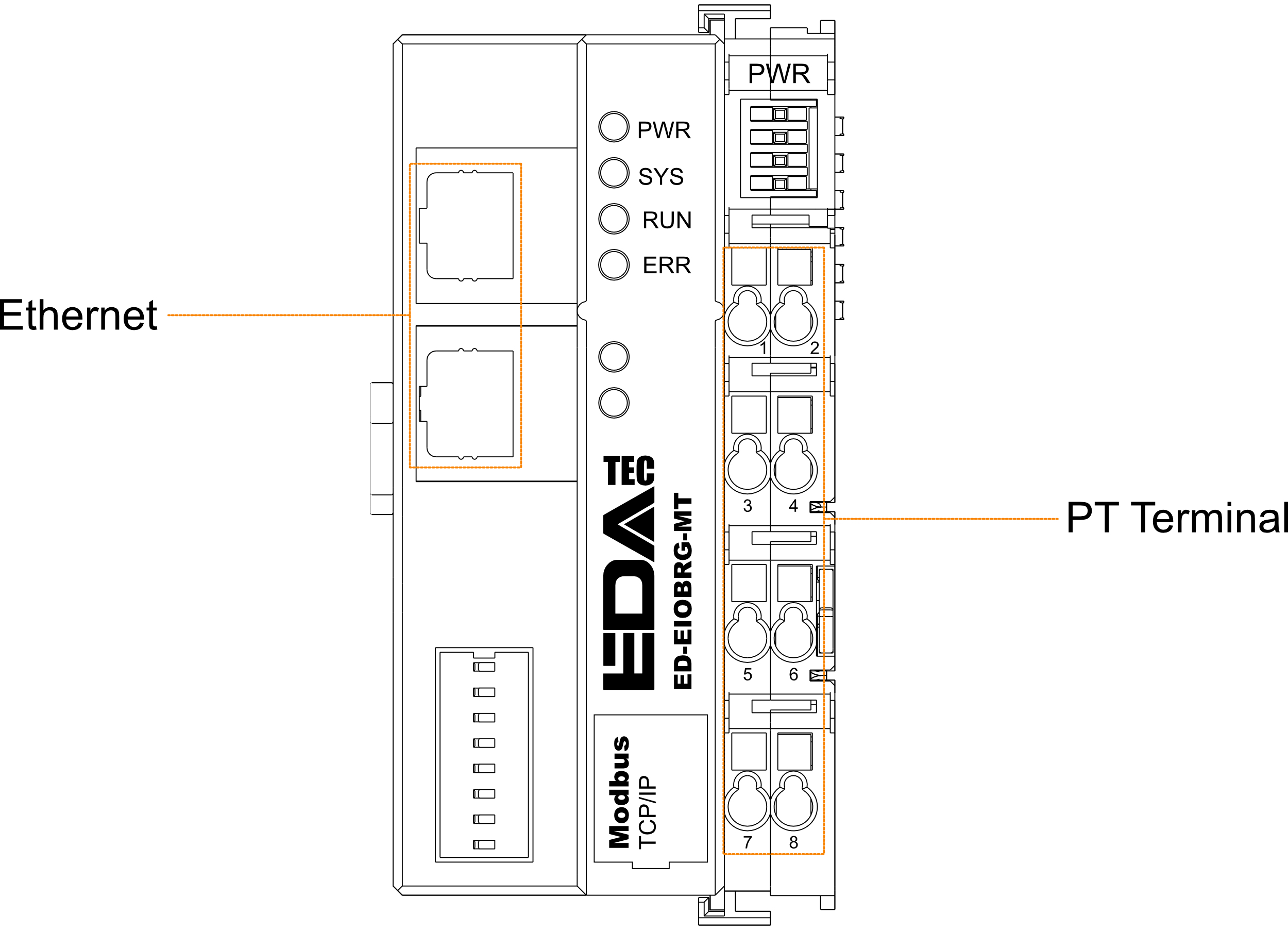
- The 2 100M Ethernet ports use standard RJ45 connectors, designated as IN and OUT ports, for communication with the upper-level control system and system networking.
| Ethernet Ports | |
|---|---|
| IN | Input port, used to connect to a Modbus TCP master or the OUT port of another Modbus TCP slave on the same subnet. |
| OUT | Output port, used to connect to the IN port of another Modbus TCP slave on the same subnet. |
- The 8 PT terminals are push-in spring-type terminals used for connecting the system-side and field-side power supplies.
| PT Terminals | |||
|---|---|---|---|
| Pin No. | Description | Pin No. | Description |
| 1 | 24V SYS | 2 | 0V SYS |
| 3 | 24V Field | 4 | 24V Field |
| 5 | 0V Field | 6 | 0V Field |
| 7 | PE | 8 | PE |
1.1.2 Indicator
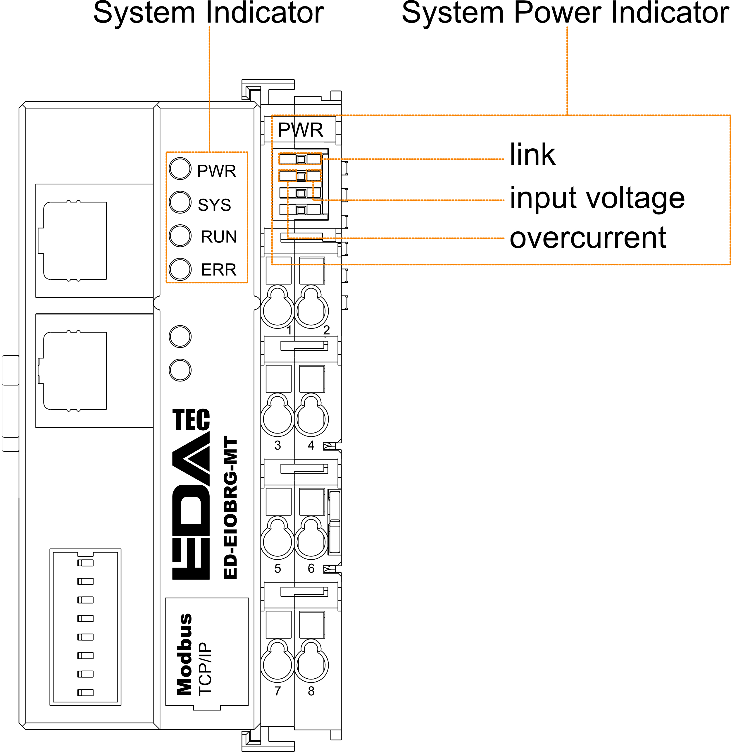
The ED-EIOBRG-MT includes 4 system indicators and 3 power supply indicators, as shown in the figure below.
| System Indicator | |
|---|---|
| PWR | Coupler power indicator, green, indicates the connection status of the system power supply.
|
| SYS | System status indicator, green, indicates the operating status of the coupler.
|
| RUN | Run indicator, green, indicates the running status of the coupler.
|
| ERR | Fault indicator, red, indicates whether an I/O module has gone offline.
|
| System Power Indicators | |
|---|---|
| Link Indicator | Green, indicates whether the common terminal wiring is correct.
|
| Input Voltage Indicator | Green, indicates whether the input voltage is normal.
|
| Overcurrent Indicator | Red, indicates whether the coupler exceeds its maximum operating current.
|
1.2 Networking and Connection
The ED-EIOBRG-MT supports connecting I/O modules and must be used with a Modbus TCP master. It also supports cascading with other Modbus TCP slaves. The specific system networking diagram is shown below.
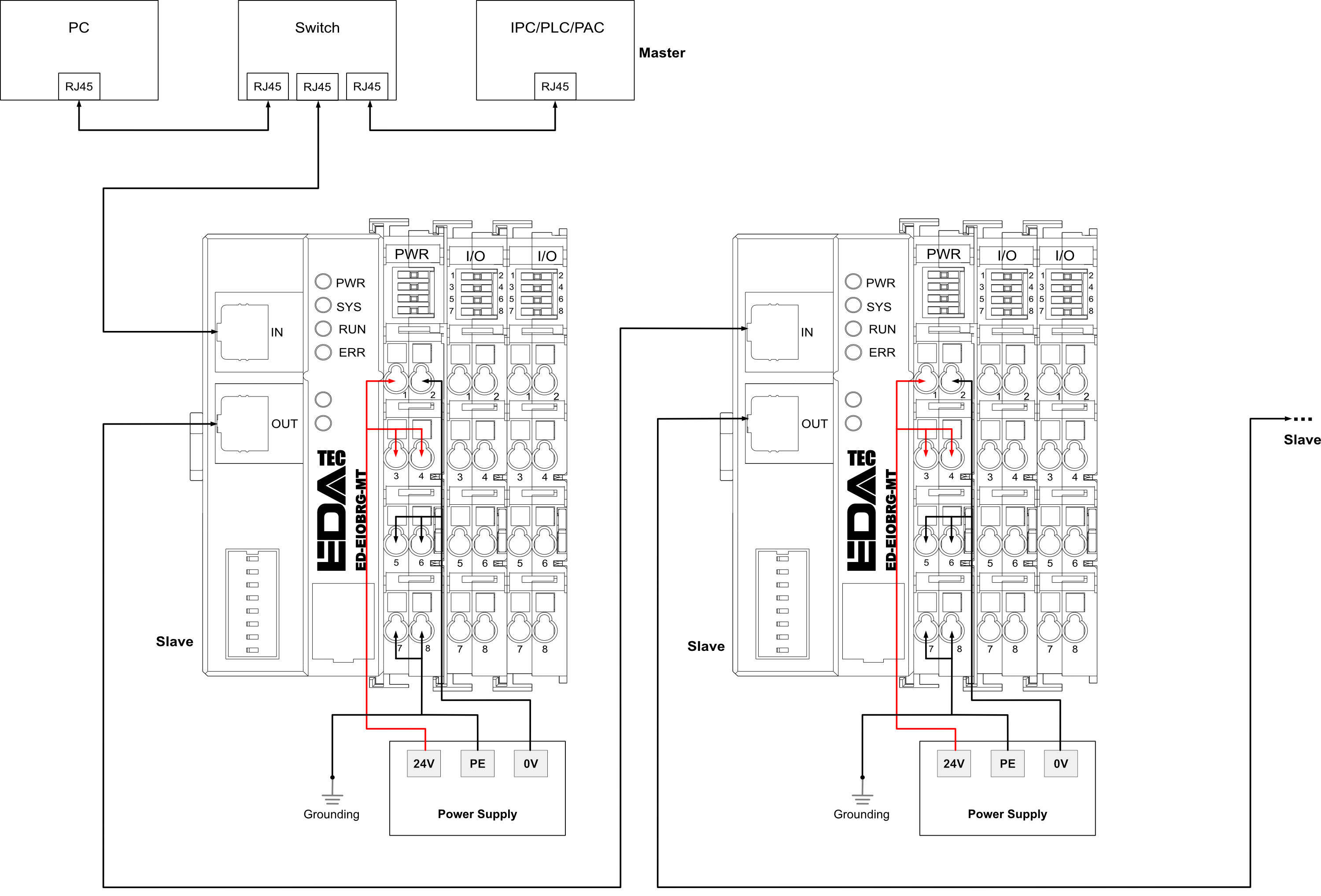
- The ED-EIOBRG-MT coupler connects to the Modbus TCP master via the Ethernet.
- Multiple ED-EIOBRG-MT couplers support cascading.
- The IP addresses of the Modbus TCP master, windows PC, and ED-EIOBRG-MT must be on the same subnet.
- A Windows PC (with configuration software installed) can be used to configure the coupler parameters.
- The I/O modules (digital input/output, analog input/output, etc.) mounted on each ED-EIOBRG-MT communicate with the coupler via the internal backplane bus. The coupler automatically scans and identifies the model and order of each I/O module. A single ED-EIOBRG-MT supports mounting up to 32 I/O modules.
- Each ED-EIOBRG-MT requires a DC 24V power supply. The wiring steps are as follows:
- Strip approximately 8-10 mm of insulation from the wire end;
- Use a flat-blade screwdriver (recommended size 2×75mm) to vertically insert into the square hole above the terminal and press down to open the spring;
- Insert the stripped wire into the round wiring hole, then remove the screwdriver; the spring will automatically reset and clamp the wire.
TIP
When connecting the power cable, strictly follow the wiring instructions shown in the diagram above. Be sure to distinguish between the positive and negative terminals of the power supply and avoid reverse connection; otherwise, the module may malfunction, operate abnormally, or even become damaged.
1.3 Configurting Parameters
1.3.1 Configuring ED-EIOBRG-MT Parameters
The ED-EIOBRG-MT supports parameter configuration via the host computer software. The following sections detail how to use the IO Controller software to complete the configuration.
1.3.1.1 Configuring Network
The default IP address of the ED-EIOBRG-MT at the factory is 192.168.0.50. In actual use, its IP address must be configured to be on the same subnet as the Modbus TCP master.
Preparation:
- The IO Controller software has been downloaded onto a Windows PC. Download link: IO Controller V1.2.3.zip.
- The physical connections for the ED-EIOBRG-MT have been completed, ensuring that the IP addresses of the Modbus TCP master, Windows PC, and ED-EIOBRG-MT are on the same subnet.
Steps:
Unzip the downloaded
IO Controller V1.2.3.zip.In the unzipped
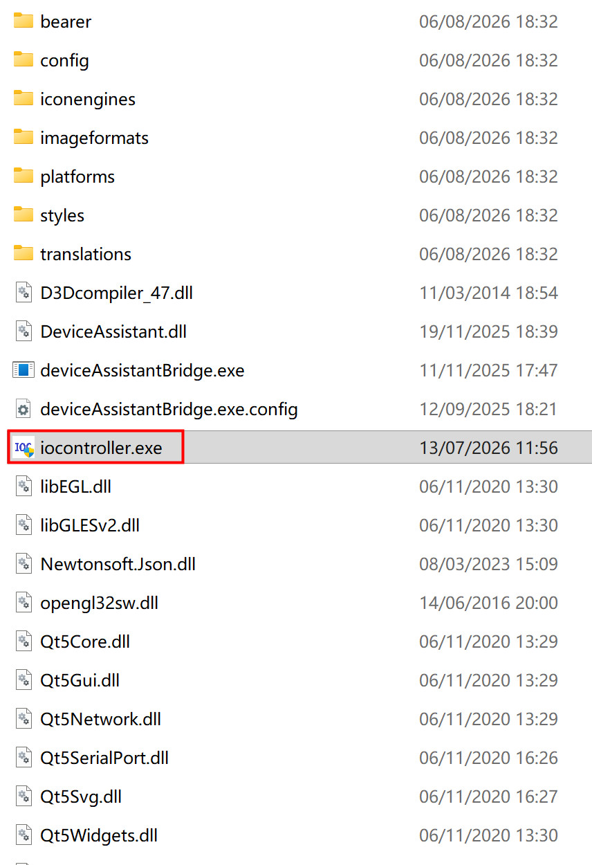
IO Controller V1.2.3folder, double-clickiocontroller.exeto run the IO Controller software.
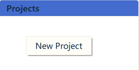
- In the opened interface, right-click on the blank area under the "Projects" region and select "New Project".
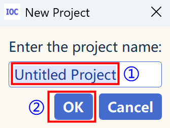
- Customize the project name, then click "OK".
- Left-click on the newly created project "test". Configure the project properties in the "Properties" area.
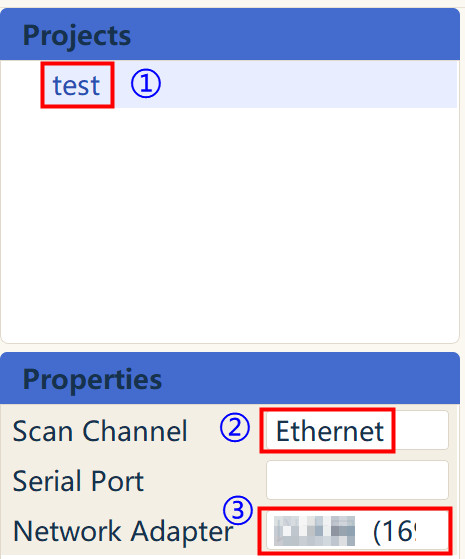
- Scan Channel: Select "Ethernet"
- Serial Port: Not required
- Network Adapter: Select the IP address of the Windows PC
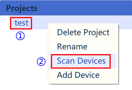
- Right-click on the newly created project "test" and select "Scan Devices".
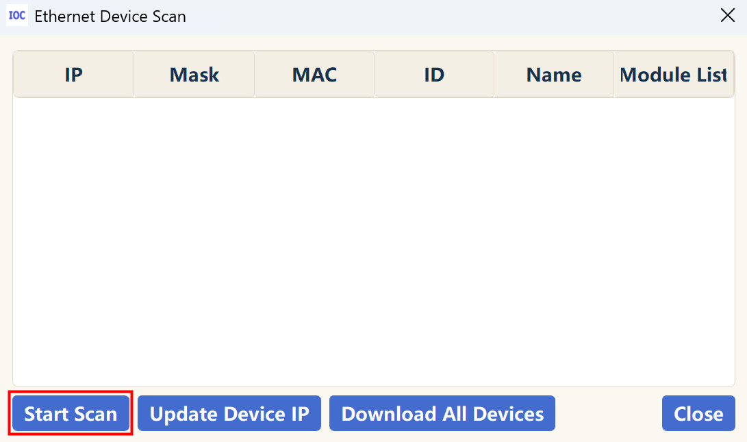
- In the "Ethernet Device Scan" window, click "Start Scan" at the bottom to obtain the IP address information of the ED-EIOBRG-MT.
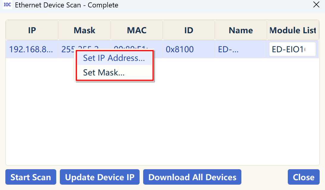
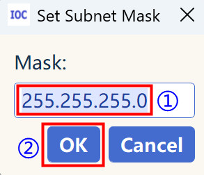
- Right-click on the scanned IP address entry and select "Set IP Address..." or "Set Mask..." from the context menu.
- Set the IP address and subnet mask as needed.
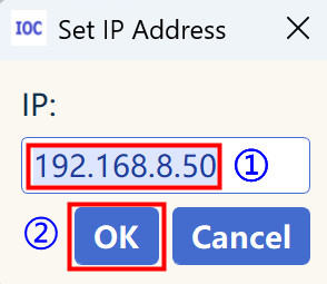
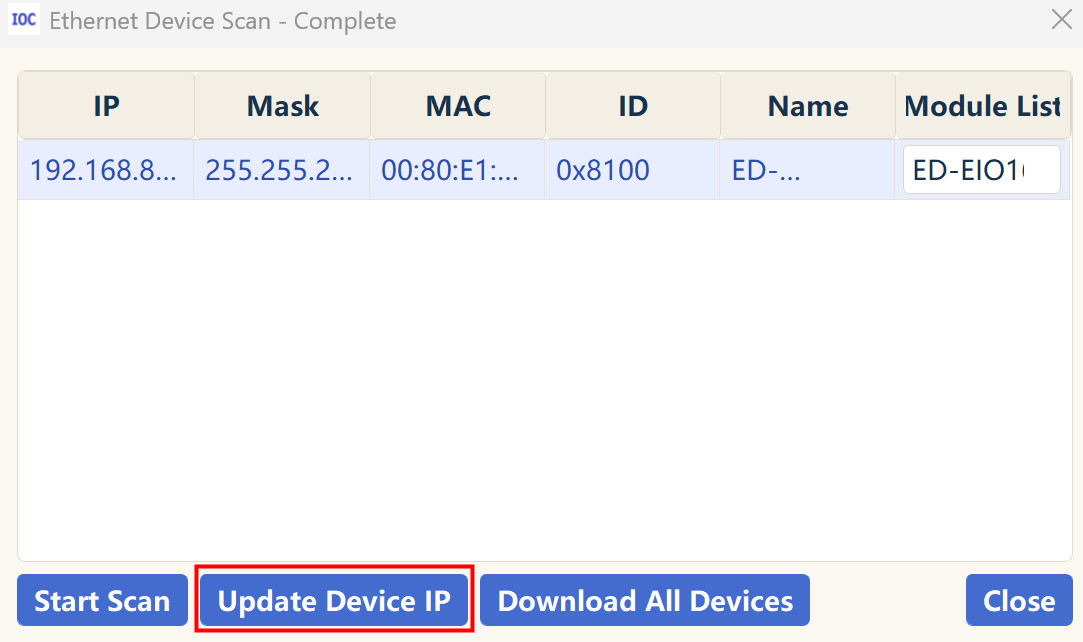
- After setting the IP address, click "Update Device IP".
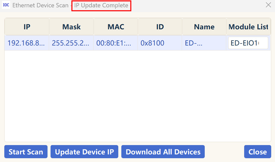
- Once the IP address update is complete, the title bar at the top of the window will display "IP Update Complete".
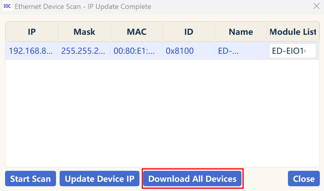
- Click "Download All Devices" at the bottom of the window to download the data for the ED-EIOBRG-MT and its expanded I/O modules.
- After the download is complete, the information for the ED-EIOBRG-MT and its expanded I/O modules will be displayed in the interface.
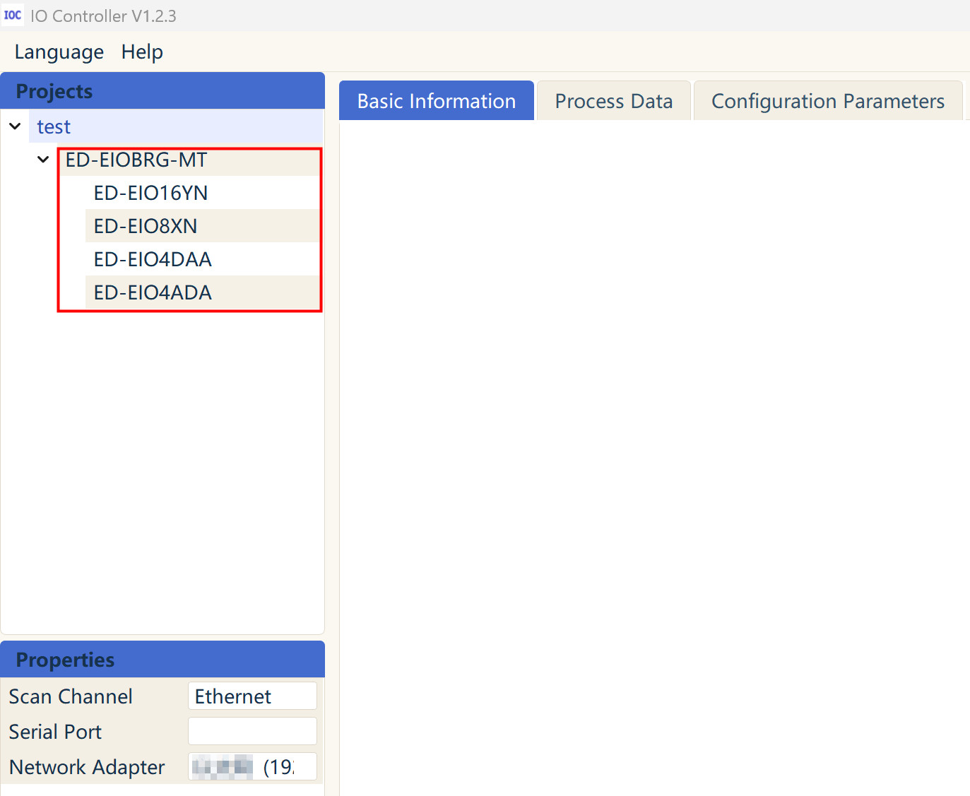
1.3.1.2 Setting Other Parameters
The port number, Watchdog, and Slave Output Hold/Clear mode of the ED-EIOBRG-MT can all be set via the IO Controller software. The specific operations are detailed below.
Preparation:
- The IP address of the ED-EIOBRG-MT has been set.
- The device download for the ED-EIOBRG-MT and I/O modules has been completed.
Steps:
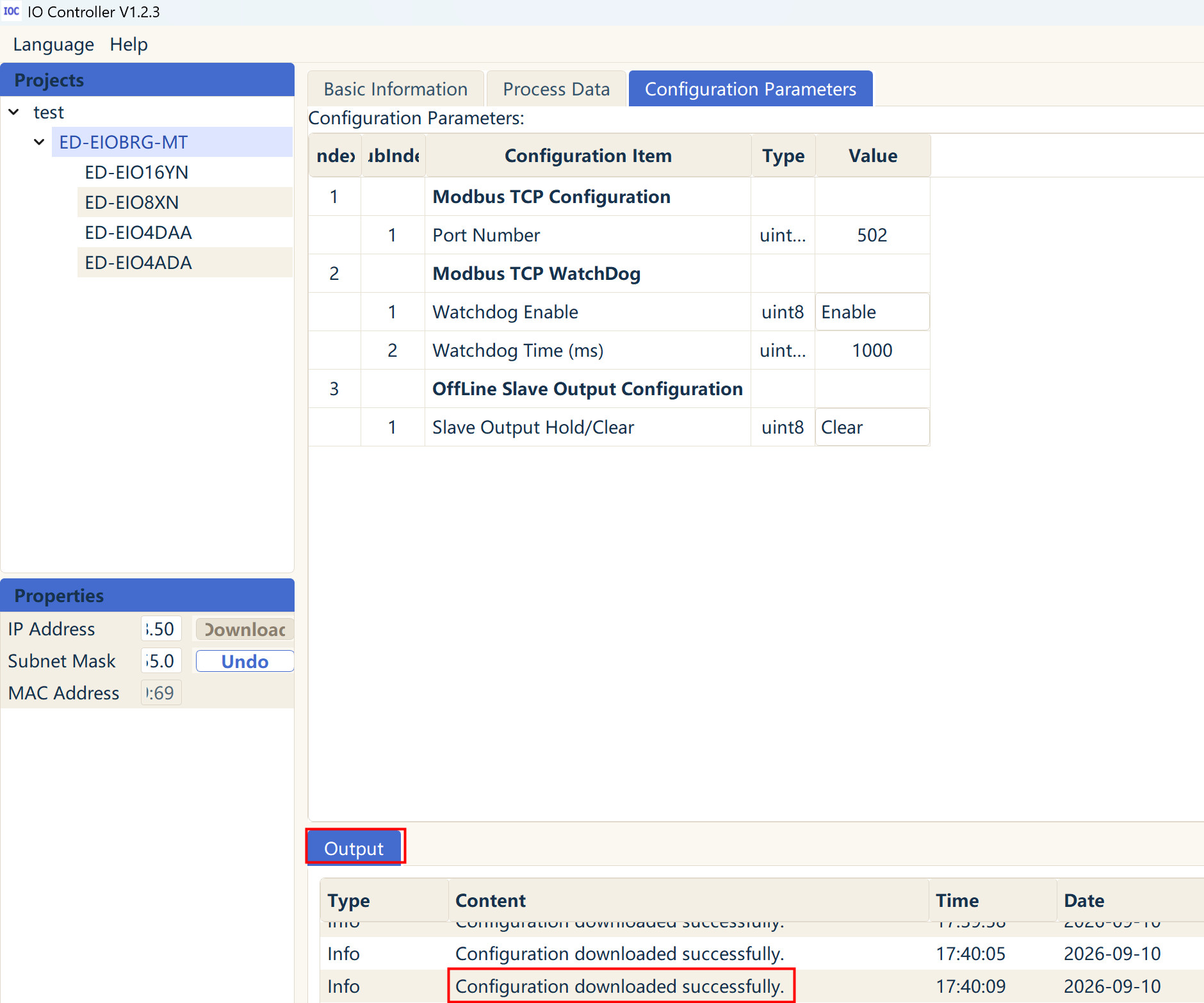
- In the left panel of the interface, under the "test" project, left-click on "ED-EIOBRG-MT". Then, select the "Configuration Parameters" tab on the right side.
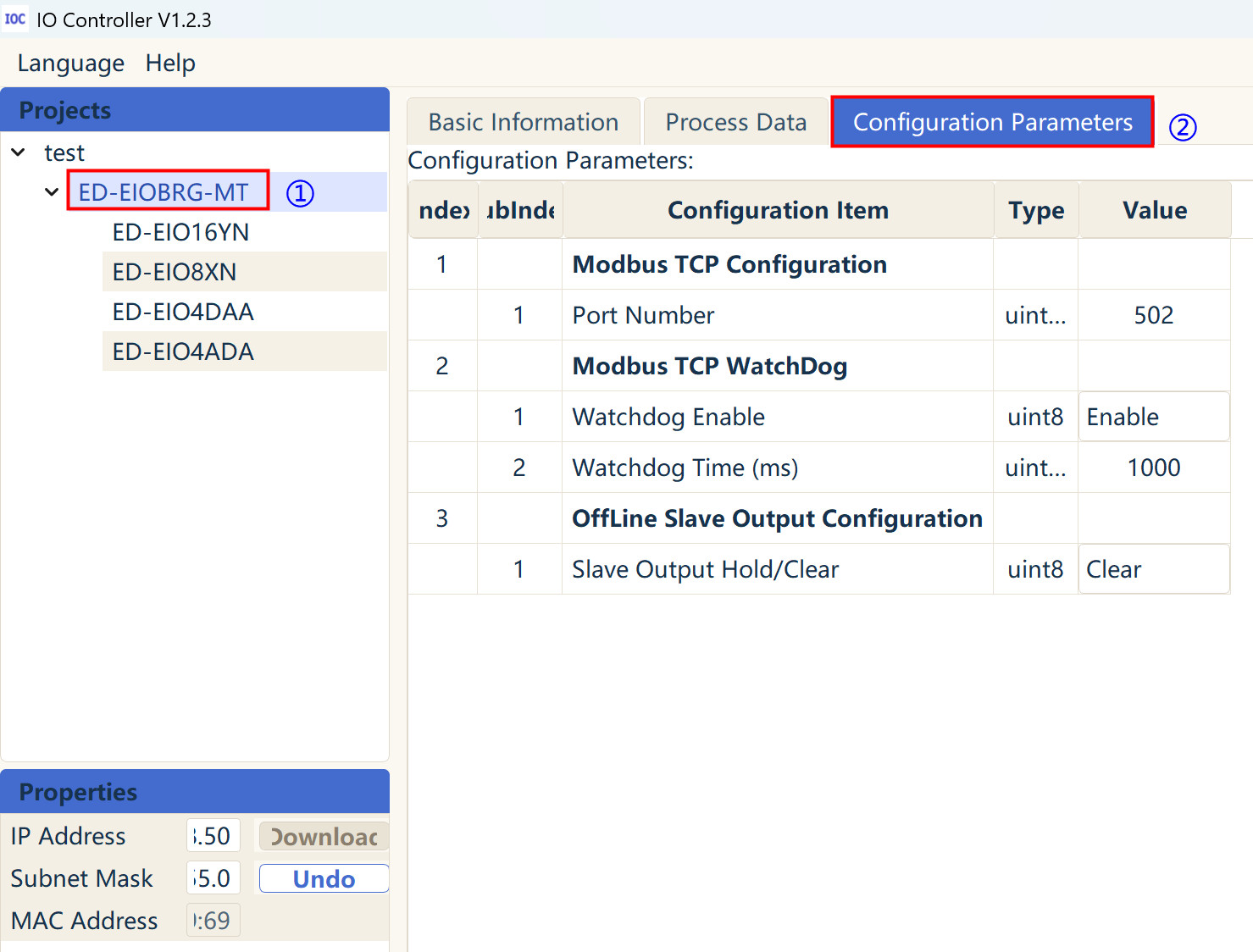
- Double-click the value in the "Value" column of the "Configuration Parameters" table to modify parameters such as "Port Number", "Watchdog Enable", "Watchdog Time (ms)", and Slave Output Hold/Clear as needed.
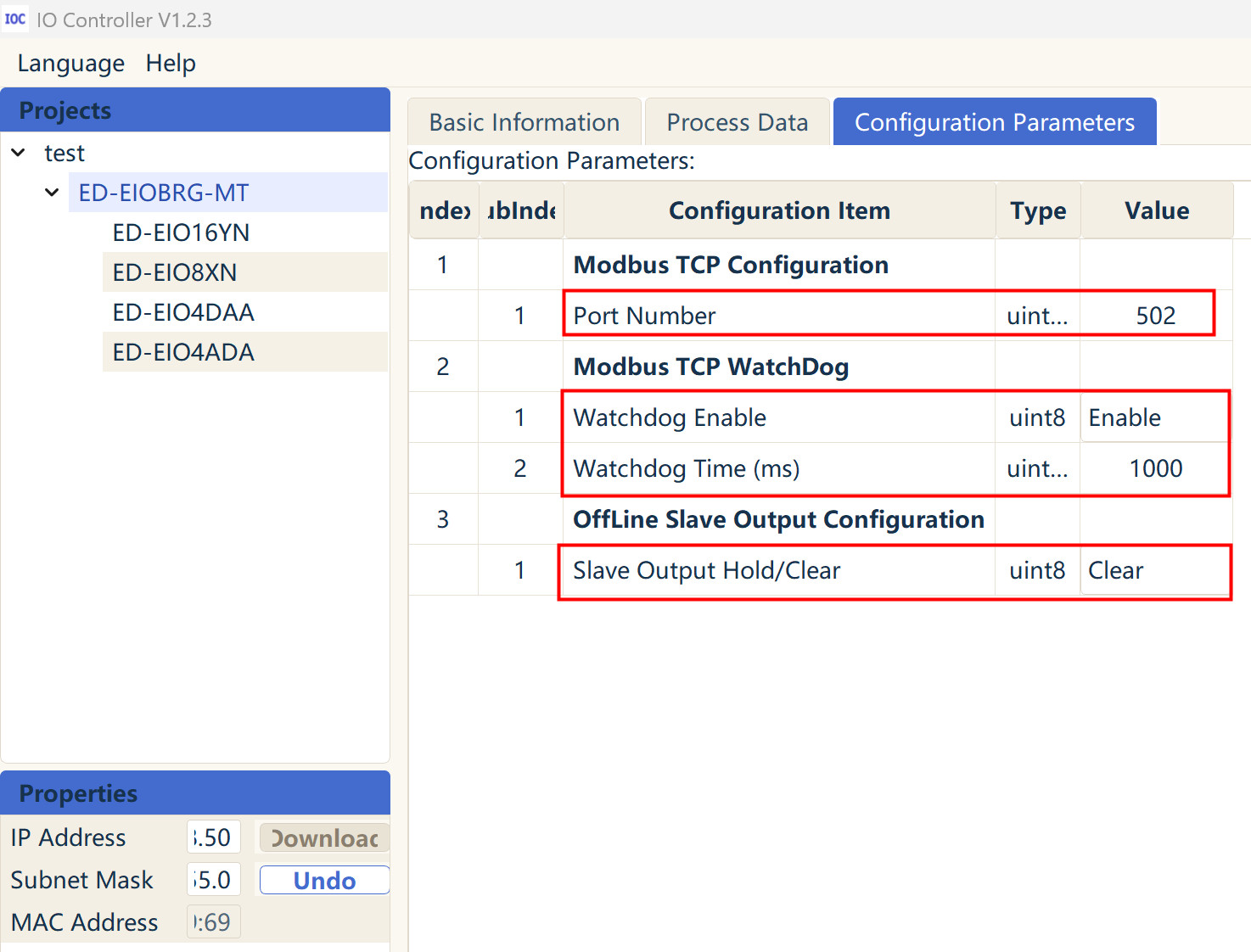
- The description of the configurable parameters is as follows:
| Parameter | Description |
|---|---|
| Port Number | Default value is 502. Range is 1~65535. Set as needed. |
| Watchdog Enable | Default value is 1. Values include 0 and 1.
|
| Watchdog Time (ms) | Default value is 180000. Range is 1000~4294967295. Set as needed. |
| Slave Output Hold/Clear | Default value is 0. Values include 0 and 1.
|
- After setting the parameters, right-click on "ED-EIOBRG-MT" under the "test" project in the left panel, and select "Download Configuration" from the menu.
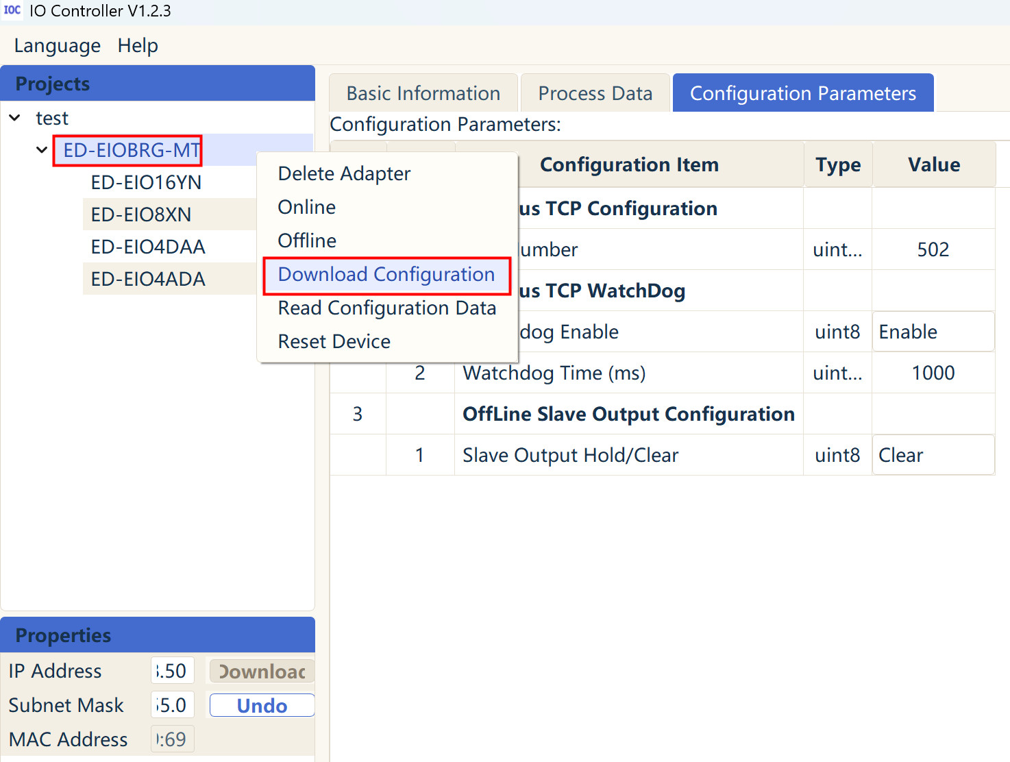
- Once the download is complete, the "Output" area at the bottom right of the interface will display the message "Configuration downloaded successfully".
1.3.2 Configuring I/O Module Parameters
The I/O modules mounted on the ED-EIOBRG-MT are classified into Digital Input (DI), Digital Output (DO), Analog Input (AI), and Analog Output (AO). DI and DO modules do not require configuration. AI and AO modules support setting the voltage and current ranges via the IO Controller software. The specific operations are detailed below.
Preparation:
- The IP address of the ED-EIOBRG-MT has been set.
- The device download for the ED-EIOBRG-MT and I/O modules has been completed.
Steps:
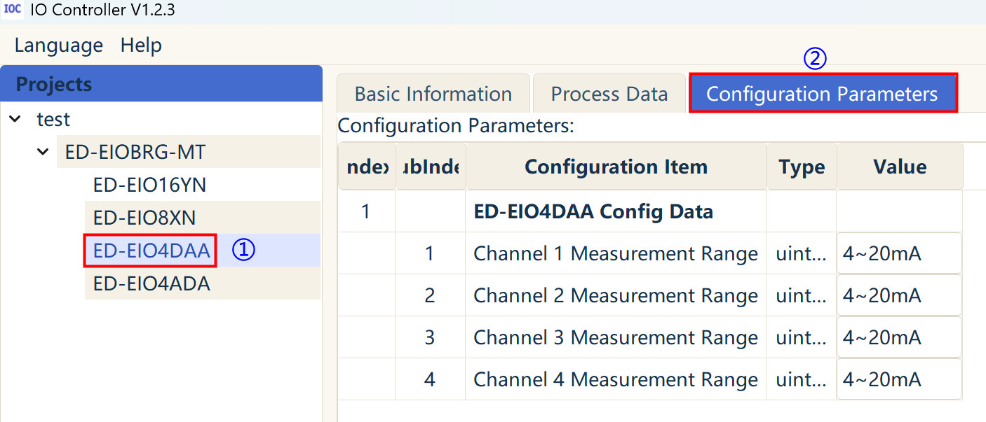
- In the left panel of the interface, under the "test" project, left-click on the I/O module (e.g., ED-EIO4DAA). Then, select the "Configuration Parameters" tab on the right side.
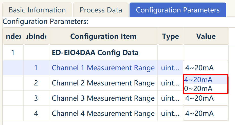
- Left-click on the voltage range value in the "Value" column of the "Configuration Parameters" table to view the list of selectable ranges. Choose the appropriate voltage range based on the actual application scenario.
TIP
- Each channel of the I/O module can be configured independently.
- This example uses one current output module for demonstration only. Operations for other module types are similar.
- After setting the parameters, right-click on "ED-EIOBRG-MT" under the "test" project in the left panel, and select "Download Configuration" from the menu.
- Once the download is complete, the "Output" area at the bottom right of the interface will display the message "Configuration downloaded successfully".