
Modbus TCP Coupler
|
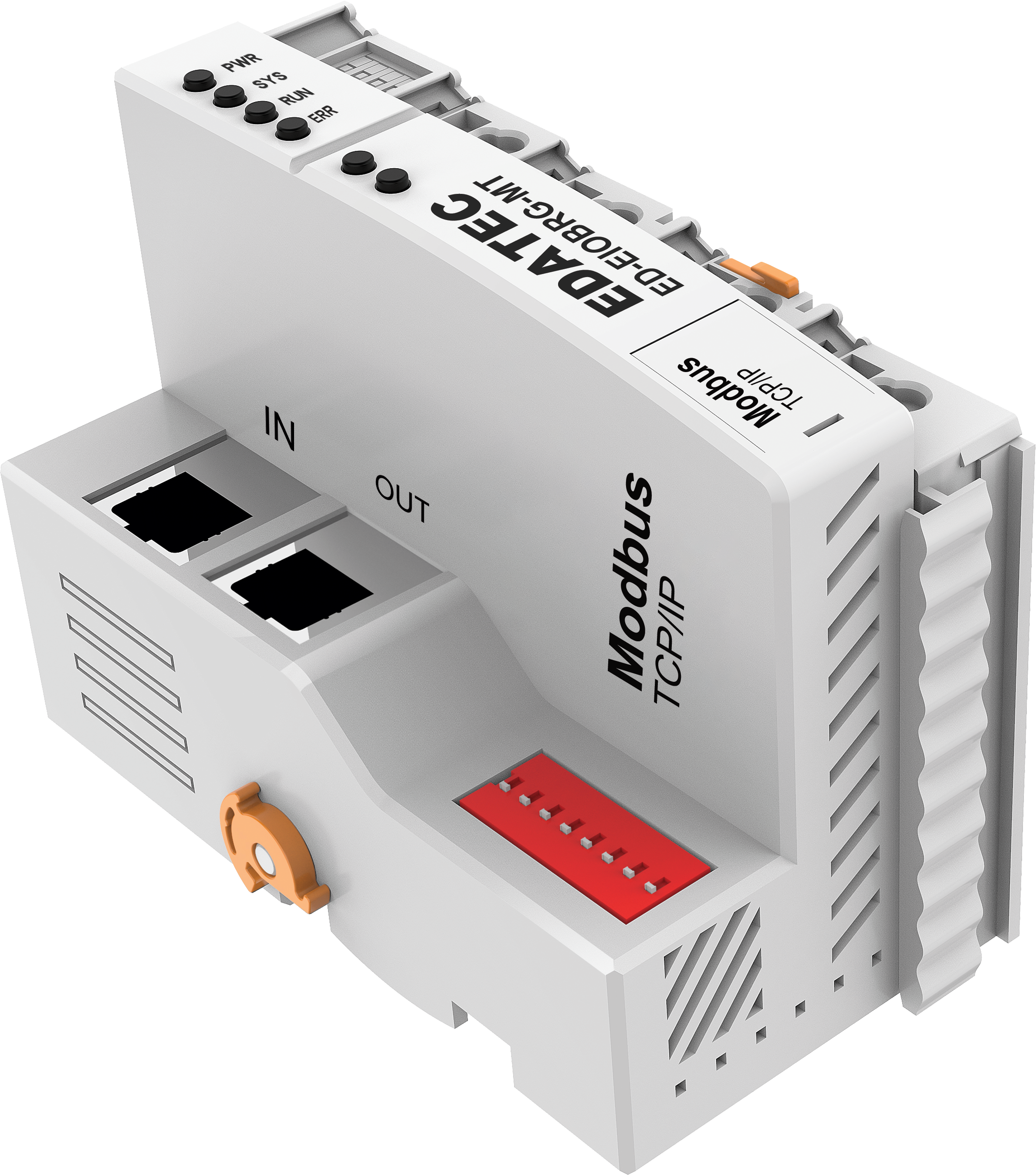
Specifications
| Communication Parameters | |
|---|---|
| Fieldbus | Modbus TCP |
| Adapter Type | Slave node |
| Mac/IP Address | Set it to the same subnet as the master station |
| Expandable I/O modules | ≤32 |
| Maximum input bytes | 1024 Byte |
| Maximum output bytes | 1024 Byte |
| Bus Rate | 100Mbps |
| Bus Interface | RJ45 |
| Distance Between Stations | ≤100m |
| System Power | DC 24V (18V ~ 36V) |
| System Current | 2A (Max) |
| Field Power | DC 24V (±20%) |
| Field Current | 10A (Max) |
| Protection Parameter | |
|---|---|
| System Isolation Voltage | 500V |
| Reverse Polarity Protection | Support |
| Overcurrent Protection | System power: support Field power: not support |
| Overvoltage Protection | Support |
| Wiring Parameter | |
|---|---|
| Wiring Specifications | 0.2mm² ~ 1.5mm² |
| Wiring Method | Screwless |
| Mechanical Characteristics | |
|---|---|
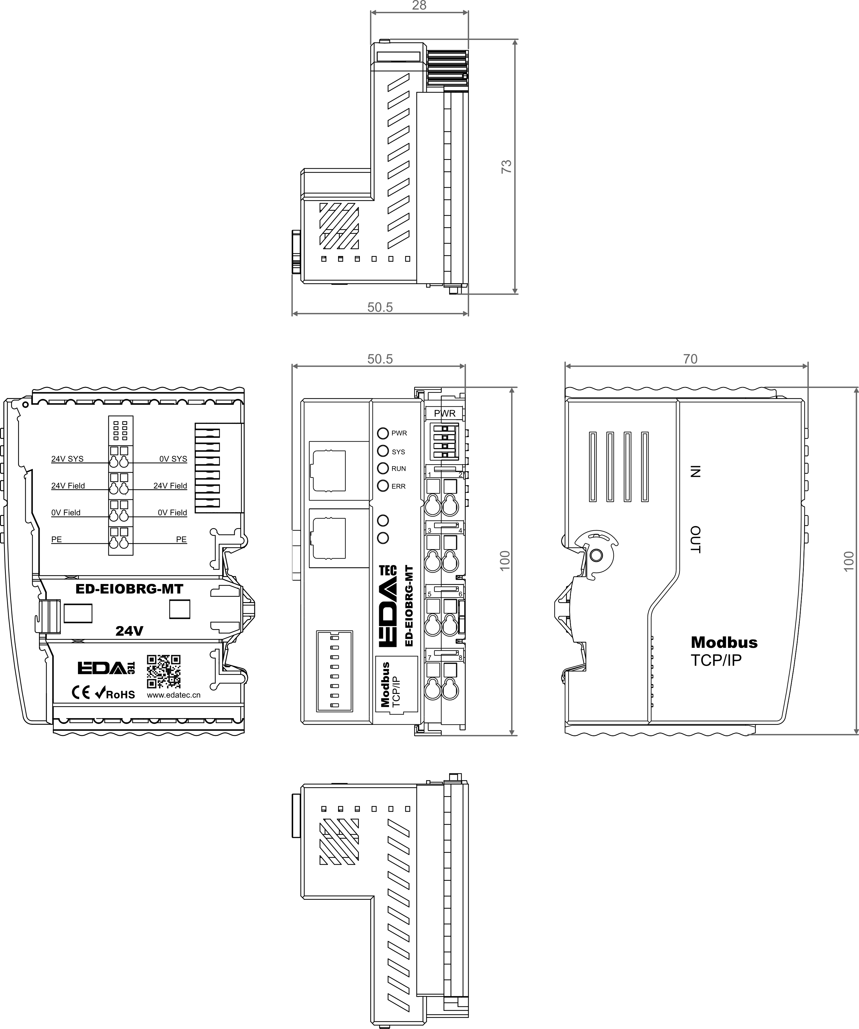
| Dimensions | 100mm x 70mm x 50.5mm |
| Weight | About 240g |
| Installation | DIN-rail installation |
| Environmental | |
|---|---|
| Operating Temperature | -10℃ ~ 55℃ |
| Storage Temperature | -20℃ ~ 85℃ |
| Ambient Humidity | 5% ~ 95% (non-condensing) |
| Standards and Certifications | |
|---|---|
| EMC | EN IEC 61000-6-4:2019 EN IEC 61000-6-2:2019 |
| RoHS | EN 62321-4:2014+A1:2017 EN 62321-5:2014 EN 62321-6:2015 EN 62321-7-1:2015 EN 62321-7-2:2017 EN 62321-8:2017 |
Interface Definition
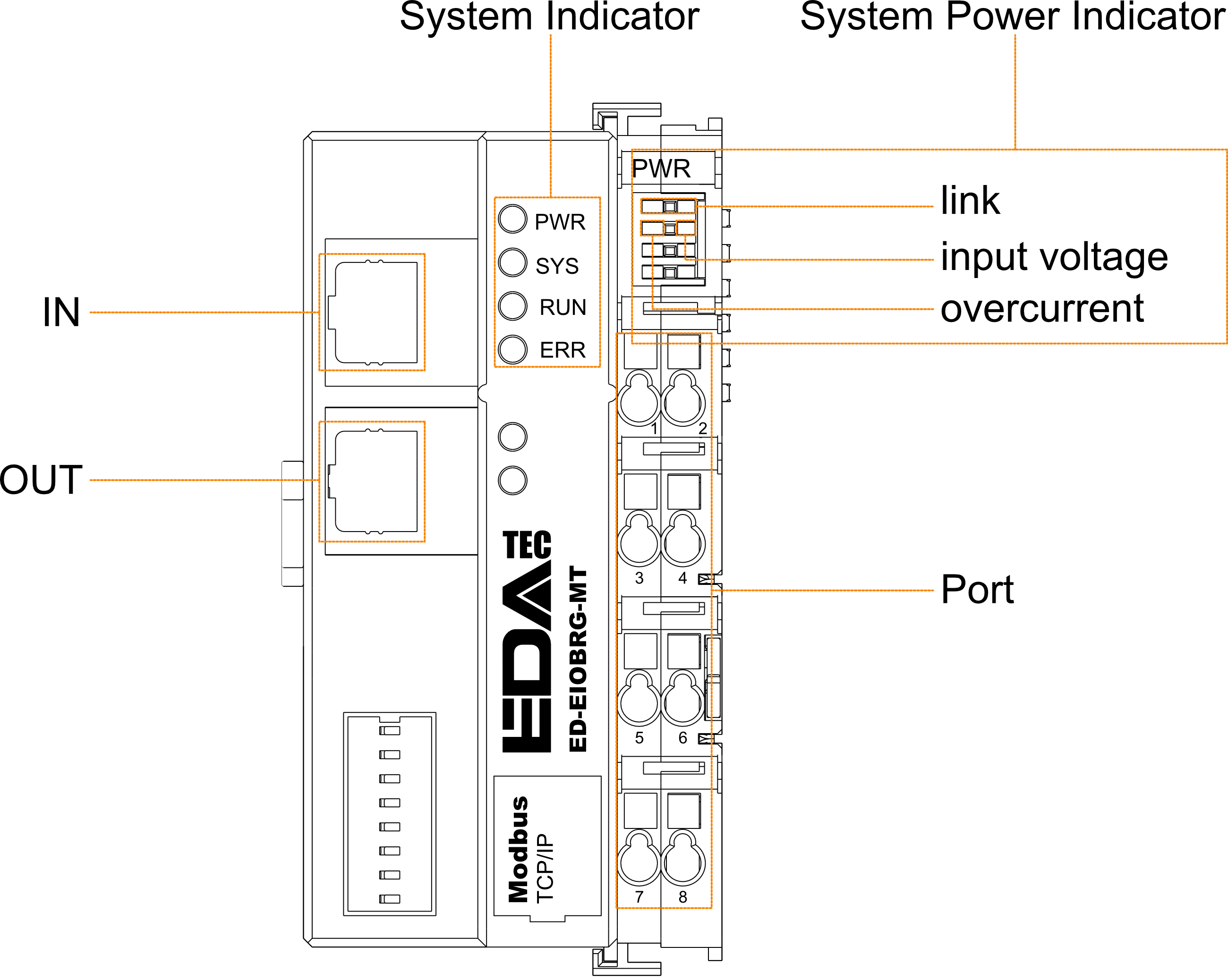
| Ethernet Port | |
|---|---|
| IN | Input port, used to connect to a Modbus TCP master station on the same subnet or to the OUT port of another Modbus TCP slave station. |
| OUT | Output port, used to connect to the IN port of other Modbus TCP slave stations on the same subnet. |
| System Indicator | |
|---|---|
| PWR | 1 x green power indicators, used to view the power status of coupler. |
| SYS | 1 x green system tip indicator, used to check the operational status of coupler. |
| RUN | 1 x green running indicator, used to check the running status of coupler. |
| ERR | 1 x red fault indicator, used to see if the coupler is malfunctioning. |
| System Power Indicator | |
|---|---|
| Link | 1 x green link indicator, used to see if the connection of common terminal is normal. |
| Input Voltage | 1 x green input voltage indicator, used to see if the input voltage is normal. |
| Overcurrent | 1 x red overcurrent indicator, used to see if the coupler exceeds the maximum operating current. |
| Power Port | |||
|---|---|---|---|
| Pin No. | Description | Pin No. | Description |
| 1 | 24V SYS | 2 | 0V SYS |
| 3 | 24V Field | 4 | 24V Field |
| 5 | 0V Field | 6 | 0V Field |
| 7 | PE | 8 | PE |
Dimensions
Unit: mm
Ordering Code
| Model | Description |
|---|---|
| ED-EIOBRG-MT | Modbus TCP Coupler, 2 x Ethernet Ports |
Expandable I/O Modules
| Model | Description |
|---|---|
| ED-EIO8XP | 8-channel digital input module (PNP) |
| ED-EIO8XN | 8-channel digital input module (NPN) |
| ED-EIO16XP | 16-channel digital input module (PNP) |
| ED-EIO16XN | 16-channel digital input module (NPN) |
| ED-EIO8YP | 8-channel digital output module (PNP) |
| ED-EIO8YN | 8-channel digital output module (NPN) |
| ED-EIO16YP | 16-channel digital output module (PNP) |
| ED-EIO16YN | 16-channel digital output module (NPN) |
| ED-EIO4YR | 4-channel digital output module (Relay) |
| ED-EIO4ADV | 4-channel analog input module (voltage), -5~5V/0~10V/-10~10V, configurable |
| ED-EIO4ADA | 4-channel analog input module (current), 4-20mA/0-20mA, configurable |
| ED-EIO8ADA | 8-channel analog input module (current), 4-20mA/0-20mA, configurable |
| ED-EIO4AD | 4-channel analog input module (voltage/current mixed), -5~5V/0~10V/-10~10V/4-20mA/0-20mA, configurable |
| ED-EIO4DAV | 4-channel analog output module (voltage), -5~5V/0~10V/-10~10V, configurable |
| ED-EIO4DAA | 4-channel analog output module (current), 4-20mA/0-20mA, configurable |
| ED-EIO4RTD | 4-channel RTD Module |
| ED-EIO4TC | 4-channel TC Module |
| ED-EIO2HCD | 2-channel High Speed Counter Module |
| ED-EIOPWR | Power Expansion Supply Module |
| ED-EIOTERM | Bus End Cover |
Packing List
- 1 x Modbus TCP Coupler