1 Hardware Manual
This chapter introduces the product overview, packing list, appearance, indicator and interface.
1.1 Overview
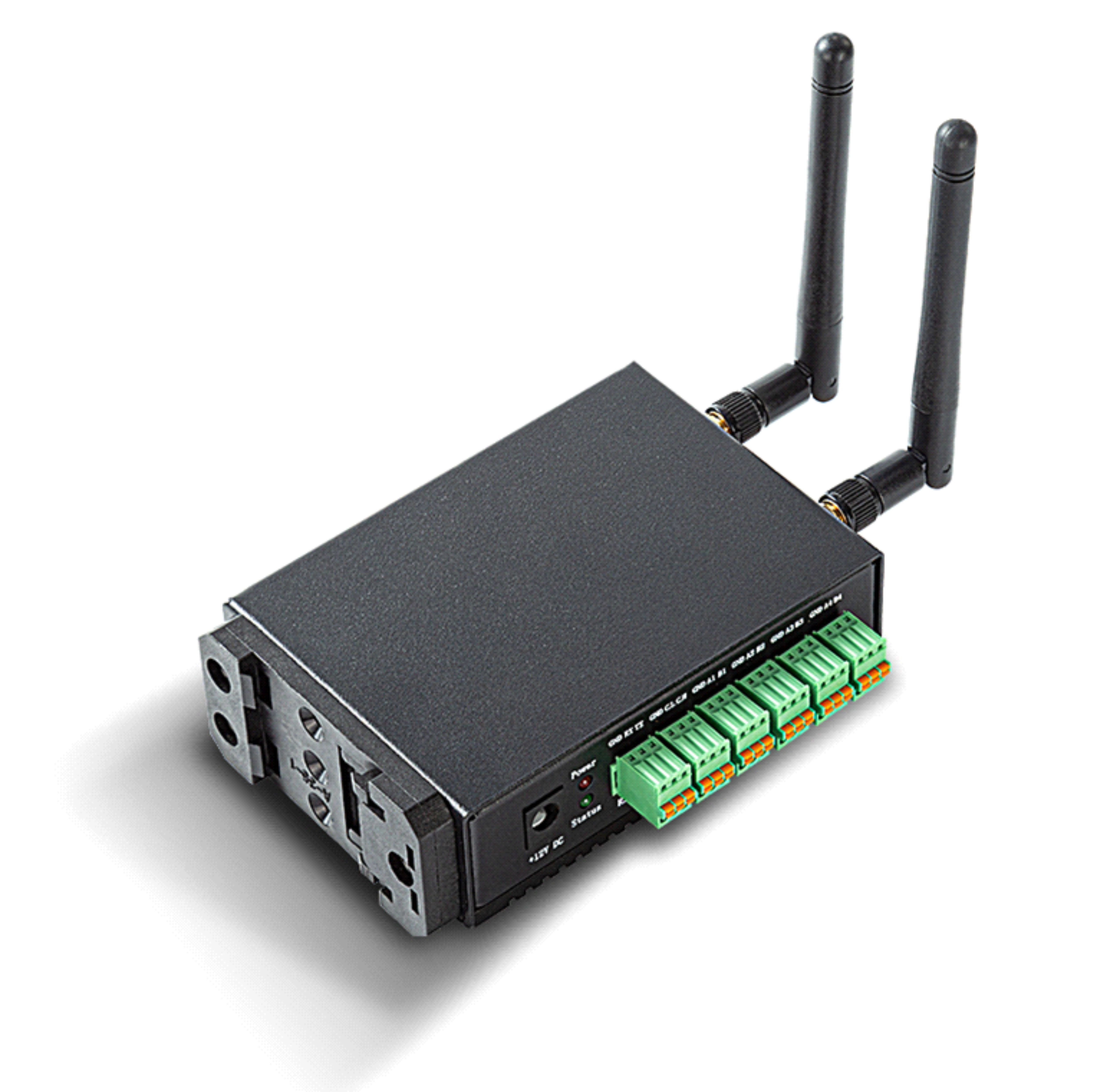
ED-CM4SEN is an industrial computer based on Raspberry Pi CM4. According to different application scenarios and user needs, different specifications of RAM and eMMC computer systems can be selected.
- RAM can choose 1GB、2GB、4GB and 8GB
- eMMC can choose 8GB、16GB and 32GB
ED-CM4SEN provides common interfaces such as HDMI, USB, Ethernet, RS232, RS485, and CAN, and supports access to the network through Wi-Fi, Ethernet, and 4G; the integrated RTC and Buzzer enhance the product's ease-of-use and reliability, and it is mainly used in the fields of industrial control and IoT.
1.2 Packing List
- 1 x ED-CM4SEN Unit
- [optional Wi-Fi/BT version] 1x 2.4GHz/5GHz Wi-Fi/BT Antenna
- [optional 4G version] 1x 4G/LTE Antenna
1.3 Appearance
Introducing the functions and definitions of interfaces on each panel.
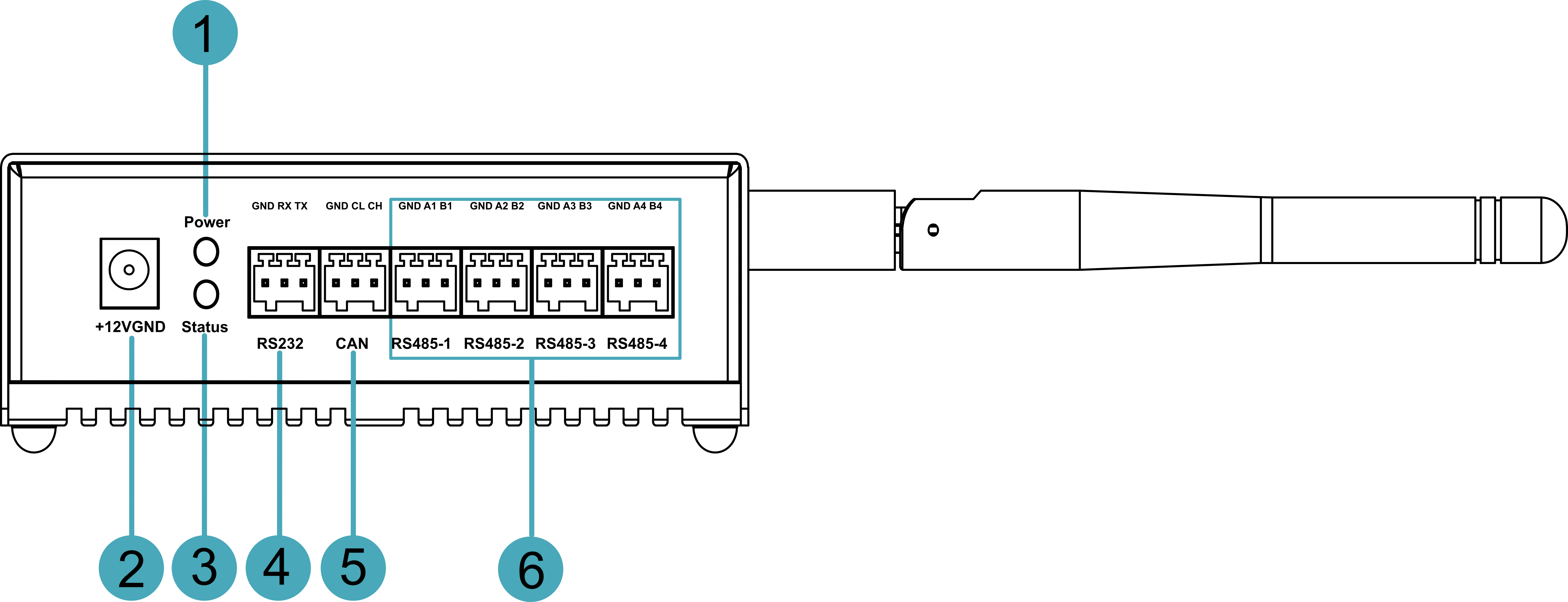
1.3.1 Front Panel
Introducing the front panel interface types and definitions.
| NO. | Function Definition |
|---|---|
| 1 | 1 x red power indicator, which is used to check the status of device power-on and power-off. |
| 2 | 1 x DC input, DC Jack connector (supports optional Phoenix terminal). It supports 8V~28V input, 12V 2A power adapter is recommended. |
| 3 | 1 x green system status indicator, which is used to check the working status of device. |
| 4 | 1 x RS232 port, 3-Pin 2.5mm pitch phoenix terminals, which is used to connect third-party control equipment. |
| 5 | 1 x CAN port, 3-Pin 2.5mm pitch phoenix terminals, which is used to connect third-party control equipment. |
| 6 | 4 x RS485 port, 12-Pin 2.5mm pitch phoenix terminals, which is used to connect third-party control equipment. |
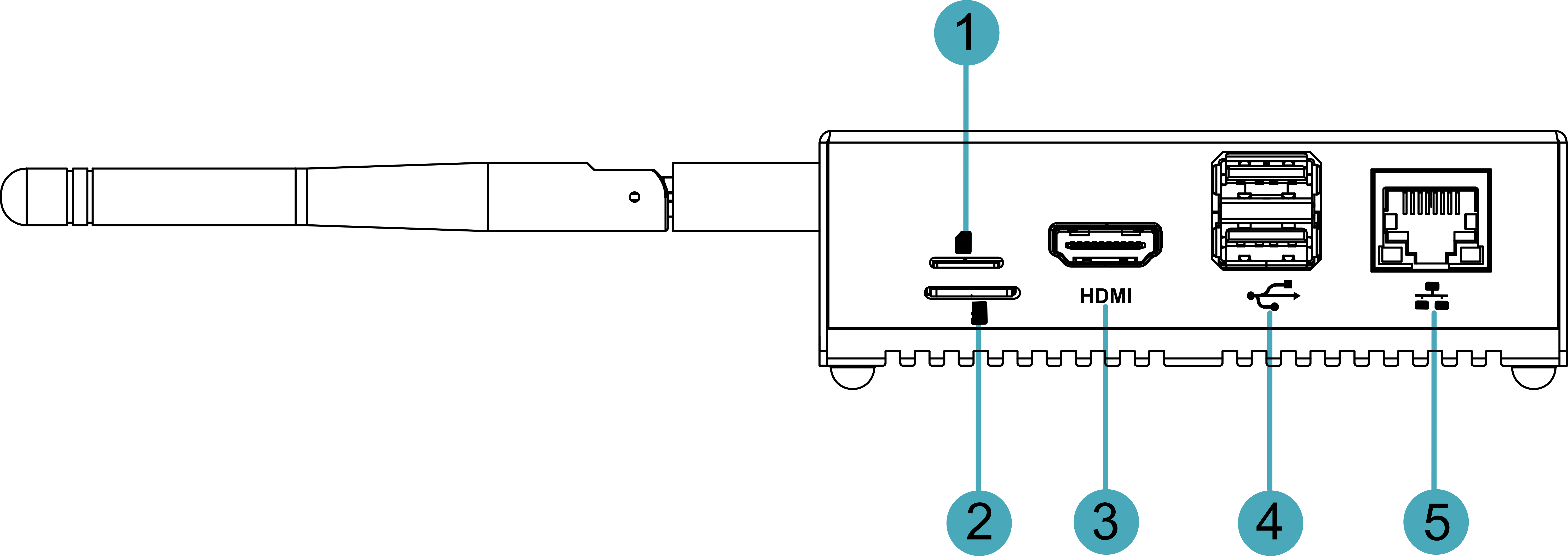
1.3.2 Rear Panel
Introducing the types and definitions of the rear panel interface.
| NO. | Function Definition |
|---|---|
| 1 | 1 x Nano SIM slot, using to install a SIM card for acquiring 4G signals. |
| 2 | 1 x Micro-SD card slot, it supports the installation of SD card for storing user data. |
| 3 | 1 x HDMI port, type A connector, which is compatibles with HDMI2.0 standard and supports 4K 60Hz. |
| 4 | 2 x USB 2.0 ports, type A connector, each channel supports up to 480Mbps transmission rate. |
| 5 | 1 x 10/100/1000M adaptive ethernet port, RJ45 connector, with led indicator. It can be used to access the network. |
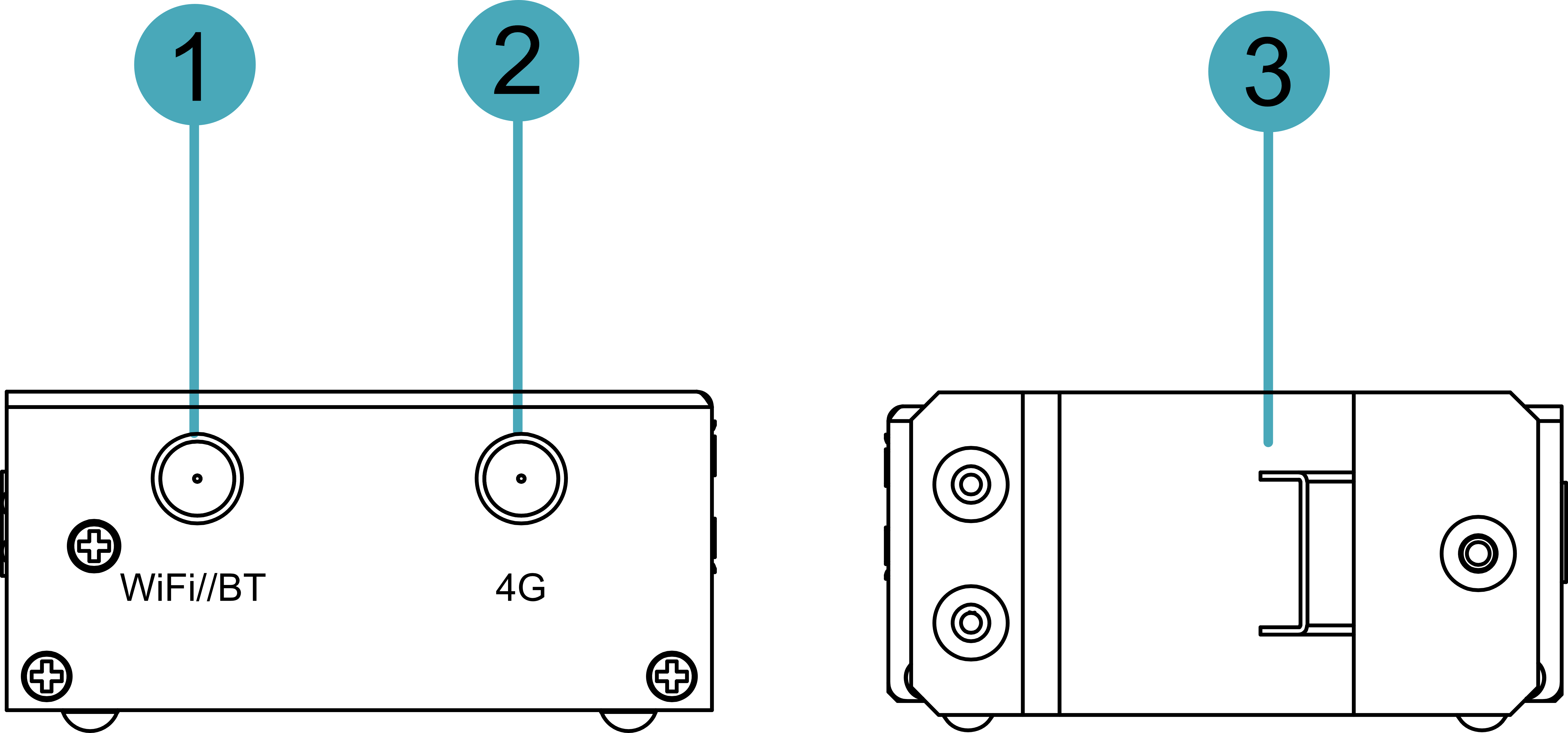
1.3.3 Side Panel
Introducing the types and definitions of side panel interfaces.
| NO. | Function Definition |
|---|---|
| 1 | 1 x Wi-Fi/BT antenna port (optional), SMA connector, which can connect to Wi-Fi/BT antenna. |
| 2 | 1 x 4G antenna port (optional), SMA connector, which can connect to 4G antenna. |
| 3 | 1 x DIN-rail bracket, install ED-CM4SEN Unit on the DIN-rail through the bracket. |
1.4 Indicator
Introducing the various statuses and meanings of indicators contained in ED-CM4SEN device.
| Indicator | Status | Description |
|---|---|---|
| Power | On | The device has been powered on. |
| Blink | Power supply of the device is abnormal, please stop the power supply immediately. | |
| Off | The device is not powered on. | |
| Status | Blink | The system started successfully and is reading and writing data. |
| Off | The device is not powered on or does not read and write data. | |
| Yellow indicator of Ethernet port | On | The data transmission is abnormal. |
| Blink | Data is being transmitted over the Ethernet port. | |
| Off | The Ethernet connection is not set up. | |
| Green indicator of Ethernet port | On | The Ethernet connection is in the normal state. |
| Blink | The Ethernet connection is abnormal. | |
| Off | The Ethernet connection is not set up. |
1.5 Interface
Introducing the definition and function of each interface in the product.
1.5.1 Power Supply Port
ED-CM4SEN includes 1 power input, using DC Jack connector (support optional Phoenix terminal). It supports 8V~28V input, the silkscreen is "+12V DC". A power adapter (12V 2A) is recommended.
1.5.2 RS232 port
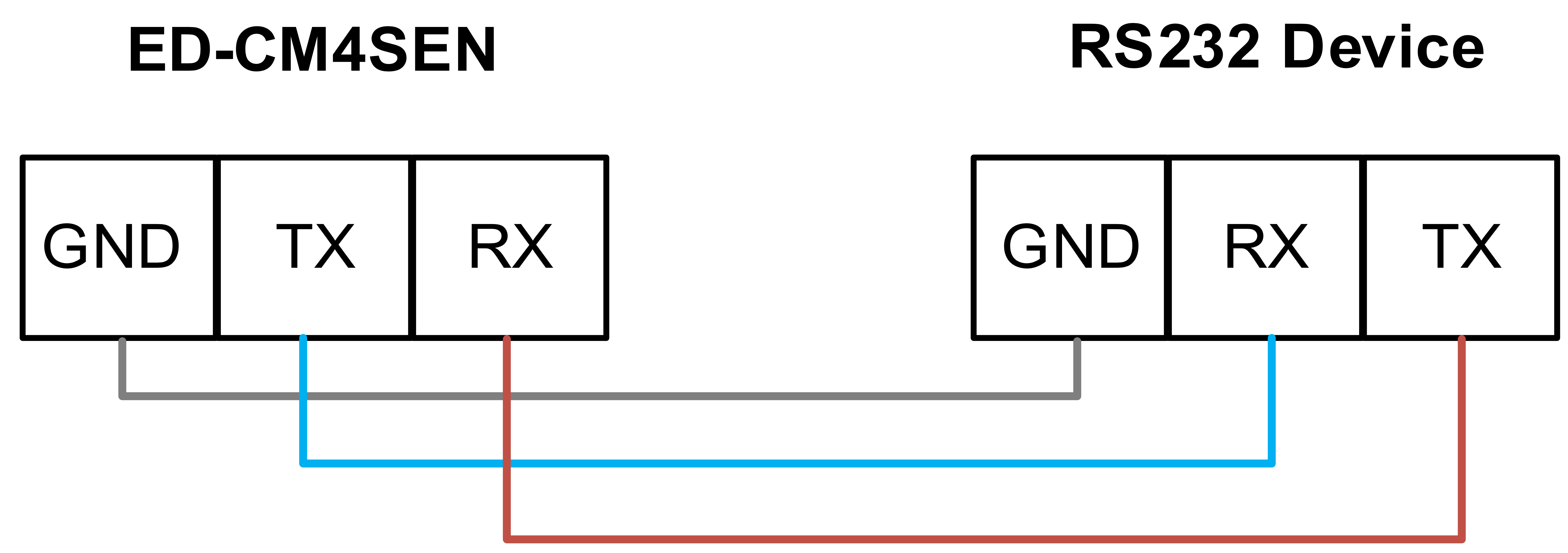
ED-CM4SEN includes 1 RS232 port, 3-Pin 2.5mm pitch Phoenix terminal, the silkscreen is "GND/RX/TX".
Pin Definition
Terminal pins are defined as follows:
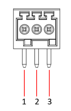 | Pin ID | Pin Name |
| 1 | GND | |
| 2 | RX | |
| 3 | TX |
The pin names of CM4 corresponding to RS232 interface are as follows:
| Signal | CM4 GPIO Name | CM4 Pin Out |
|---|---|---|
| RS232_TX | GPIO14 | UART_TXD0 |
| RS232_RX | GPIO15 | UART_RXD0 |
Connecting Cables
Schematic diagram of RS232 wires is as follows:
1.5.3 CAN Port
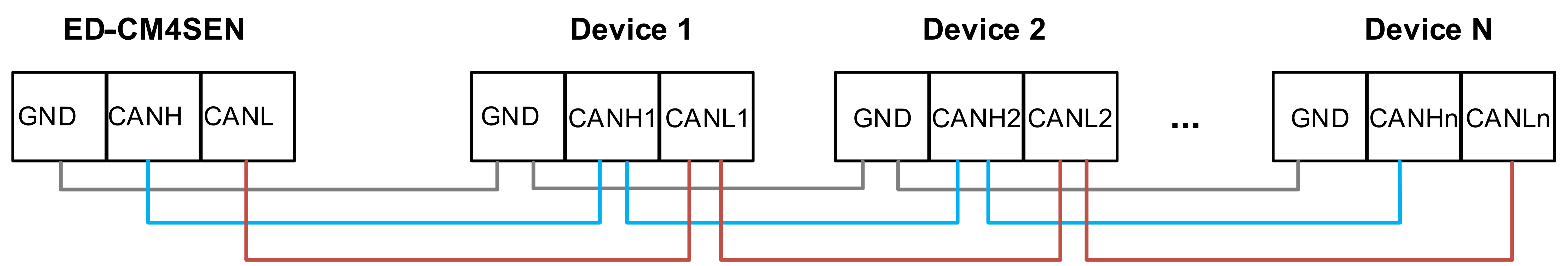
ED-CM4SEN includes 1 CAN port, 3-Pin 2.5mm pitch Phoenix terminal, the silkscreen is "GND/CL/CH".
Pin Definition
Terminal pins are defined as follows:
| Pin ID | Pin Name |
| 1 | GND | |
| 2 | CL | |
| 3 | CH |
onnecting Cables
Schematic diagram of CAN wires is as follows:
1.5.4 RS485 Port
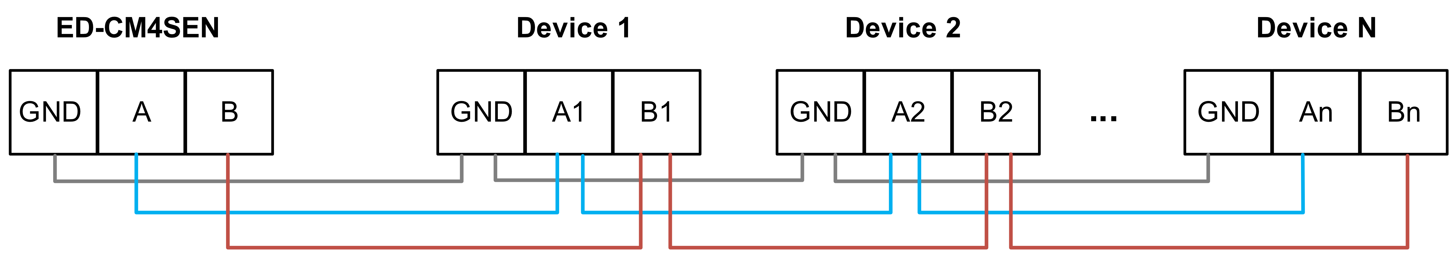
ED-CM4SEN includes 4 RS485 ports, 12-Pin 2.5mm pitch Phoenix terminals, the silkscreen of single RS485 is "GND/A/B".
Pin Definition
Terminal pins are defined as follows:
RS485-1
| Pin ID | Pin Name |
| 1 | GND | |
| 2 | A1 | |
| 3 | B1 |
The pin names of CM4 corresponding to RS485-1 interface are as follows:
| Signal | CM4 GPIO Name | CM4 Pin Out |
|---|---|---|
| RS485-1_A3 | GPIO0 | UART_TXD2 |
| RS485-1_B3 | GPIO1 | UART_RXD2 |
RS485-2
| Pin ID | Pin Name |
| 1 | GND | |
| 2 | A2 | |
| 3 | B2 |
The pin names of CM4 corresponding to RS485-2 interface are as follows:
| Signal | CM4 GPIO Name | CM4 Pin Out |
|---|---|---|
| RS485-2_A2 | GPIO8 | UART4_TXD |
| RS485-2_B2 | GPIO9 | UART4_RXD |
RS485-3
| Pin ID | Pin Name |
| 1 | GND | |
| 2 | A1 | |
| A3 | B3 |
The pin names of CM4 corresponding to RS485-3 interface are as follows:
| Signal | CM4 GPIO Name | CM4 Pin Out |
|---|---|---|
| RS485-3_A1 | GPIO4 | UART_TXD3 |
| RS485-3_B1 | GPIO5 | UART_RXD3 |
RS485-4
| Pin ID | Pin Name |
| 1 | GND | |
| 2 | A4 | |
| 3 | 4B |
The pin names of CM4 corresponding to RS485-4 interface are as follows:
| Signal | CM4 GPIO Name | CM4 Pin Out |
|---|---|---|
| RS485-4_A4 | GPIO12 | UART_TXD5 |
| RS485-4_B4 | GPIO13 | UART_RXD5 |
Connecting Cables
Schematic diagram of RS485 wires is as follows:
1.5.5 Card Slot
1.5.5.1 Micro SD Card Slot
The silkscreen on the case of Micro SD card slot is " ", which is used to install SD card for storing user data.
1.5.5.2 SIM Card Slot (optional)
The silkscreen on the case of Nano SIM card slot is " ", which is used to install SIM card for obtaining 4G signals.
1.5.6 HDMI Port
ED-CM4SEN device includes one HDMI port, the silkscreen is "HDMI". The connector is type A HDMI, which can connect to an HDMI display and supports up to 4Kp60.
1.5.7 USB 2.0 Port
ED-CM4SEN device includes 2 USB 2.0 ports, the silkscreen is " ". The connector is type A USB, which can connect to standard USB 2.0 peripherals and supports up to 480Mbps transmission rate.
1.5.8 1000M Ethernet Port
ED-CM4SEN device includes one adaptive 10/100/1000M Ethernet port, and the silkscreen is " ". The connector is RJ45. When accessing to network, it is recommended to use the network cable of Cat6 and above. The pins corresponding to the terminal are defined as follows:
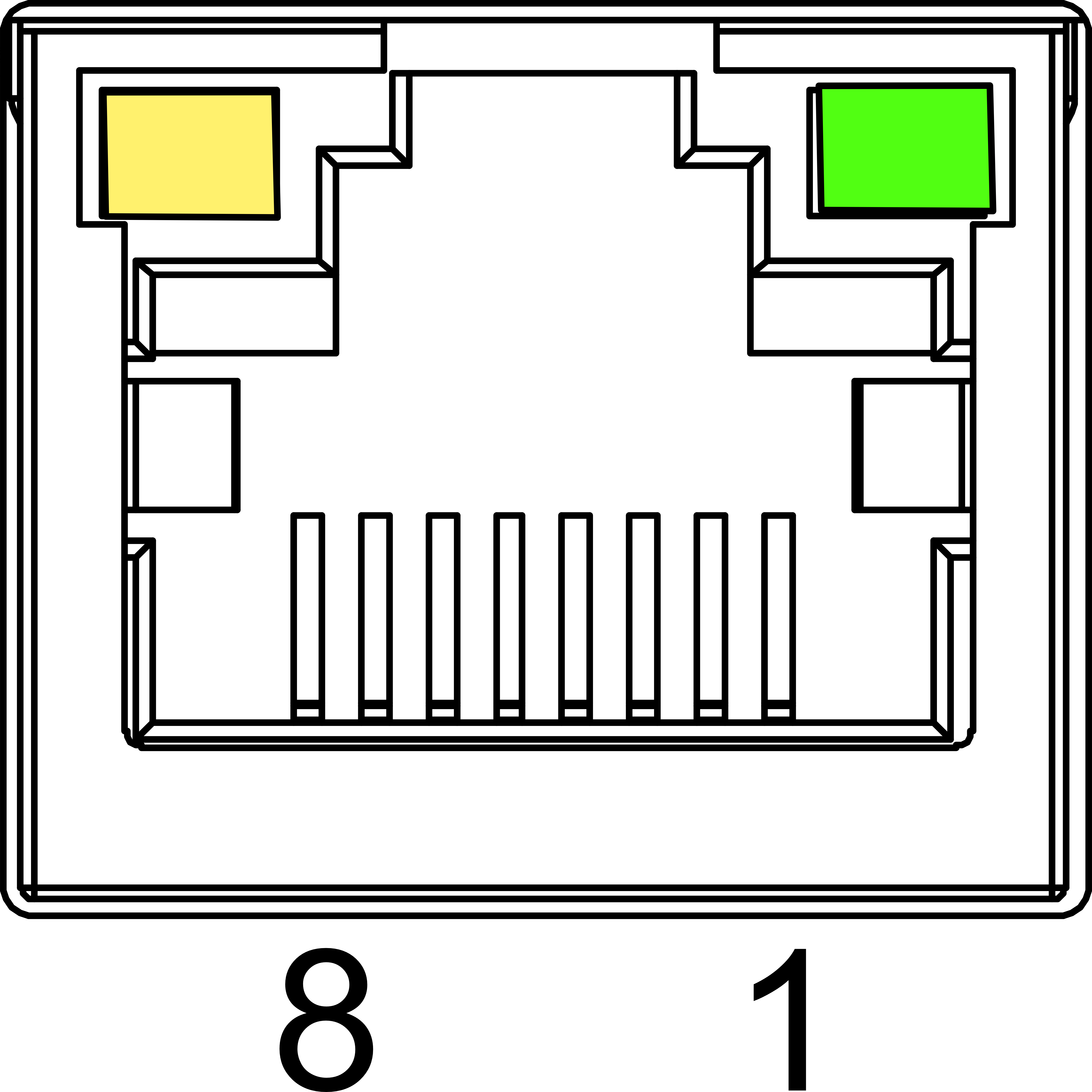 | Pin ID | |
| 1 | TX1+ | |
| 2 | TX1- | |
| 3 | TX2+ | |
| 4 | TX2- | |
| 5 | TX3+ | |
| 6 | TX3- | |
| 7 | TX4+ | |
| 8 | TX4- |
1.5.9 Antenna Port (optional)
ED-CM4SEN device includes 2 SMA antenna ports, the silkscreens are "4G" and "Wi-Fi/BT" and they can be connected to the 4G antenna and Wi-Fi/BT antenna.
TIP
The number of antenna port is related to the actual model selected by the user, and only 2 antenna ports are included here as an example.
1.5.10 Motherboard Interface
Introducing the interfaces reserved in the ED-CM4SEN device, which can be obtained only after the device case is opened (For detailed operations, please refer to 2.1.1 Open Device Case), and can be expanded according to actual needs.
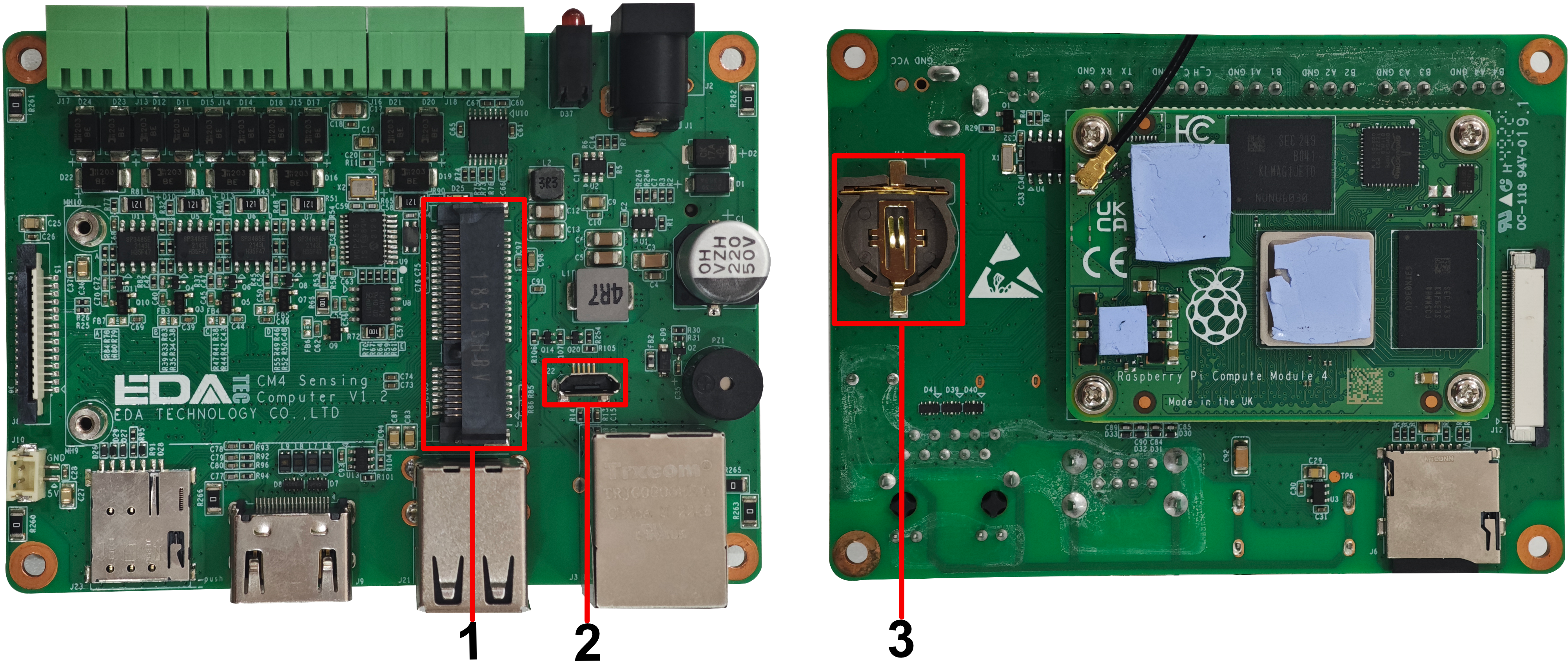
| NO. | Function Definition |
|---|---|
| 1 | Mini PCIe interface for connecting 4G modules |
| 2 | Micro-USB interface for Flashing to eMMC |
| 3 | RTC Battery base, supports installing of RTC batteries |
1.5.10.1 Micro-USB Port
The ED-CM4SEN device includes a micro USB port with silkscreen “J22”, which supports to flash to eMMC on the device by connecting to a PC.
1.5.10.2 Mini PCIe Connector
The ED-CM4SEN device includes 1 Mini PCIe connector, which supports connecting 4G module (optional). If users select the product with 4G function, the 4G module is installed by default.
1.5.10.3 RTC
The ED-CM4SEN device motherboard is equipped with an RTC function, integrating a 1F supercapacitor as the RTC backup power supply to ensure the system clock remains unaffected by device power-off. It also provides an RTC battery base, allowing users to optionally purchase a CR1220 battery (as shown in the image below) as an alternative RTC backup power source.
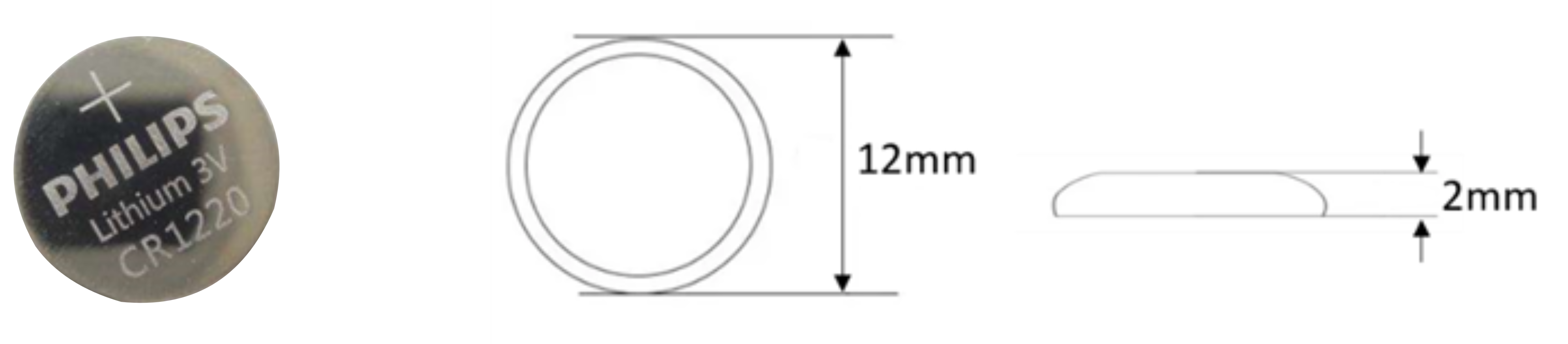
TIP
The device does not come with a CR1220 battery as standard.