1 Hardware Manual
This chapter introduces the product overview, CODESYS software, networking application, packaging list, appearance, buttons, indicators, interfaces and Supercapacitor.
1.1 Overview
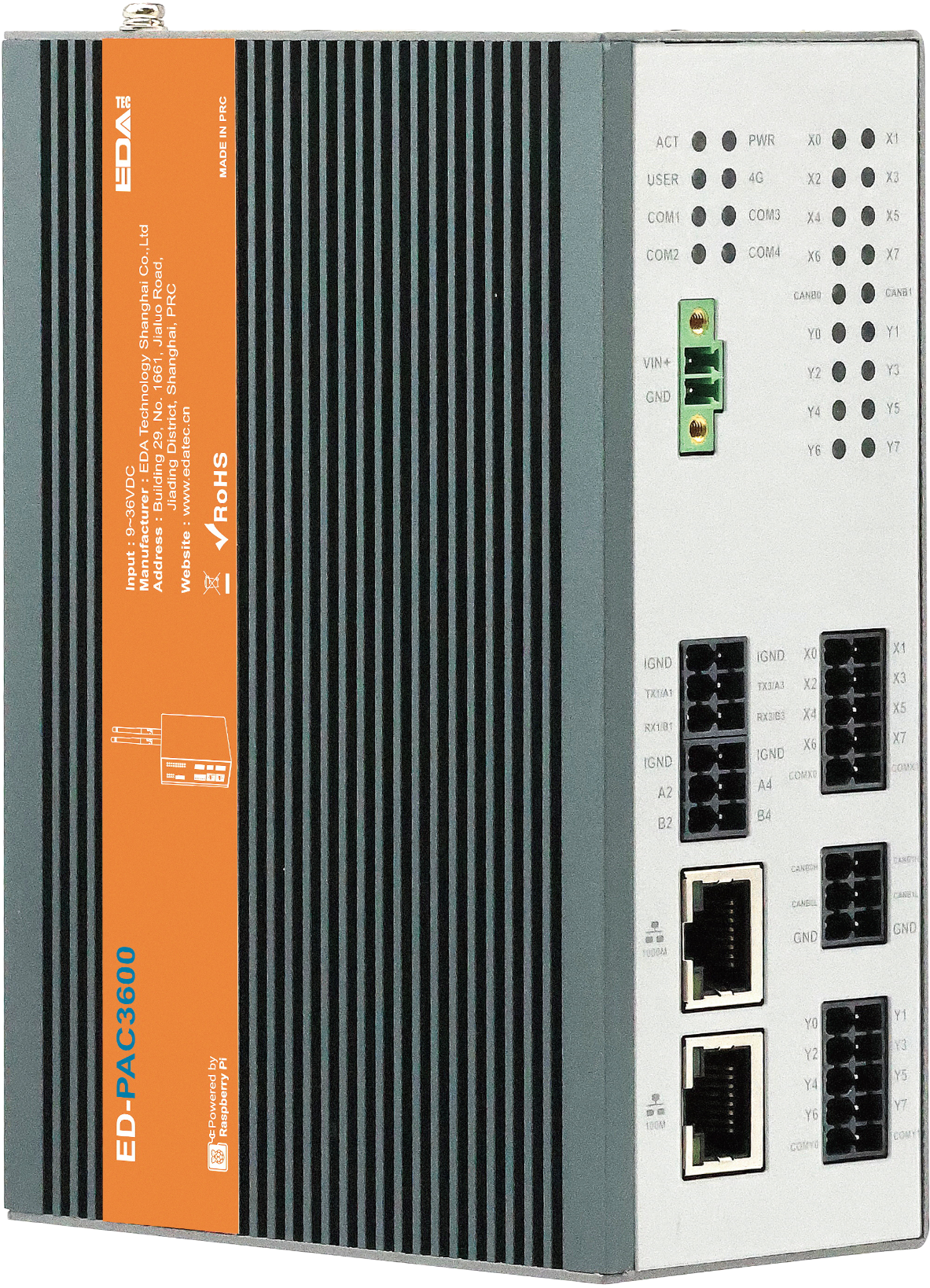
The ED-PAC3630 is a real-time CODESYS programmable automation controller, pre-installed by default with a multi-core CODESYS runtime. Depending on the application scenario and user requirements, it offers programmable logic system configurations with either 2GB DDR + 16GB eMMC or 8GB DDR + 32GB eMMC.
WARNING
The ED-PAC3630 device comes pre-installed with a valid CODESYS license by default. Reinstalling the operating system will invalidate the CODESYS license. Do not attempt to install the OS on your own.
The ED-PAC3630 provides common interfaces such as HDMI, USB, Ethernet, RS232, RS485, DI, DO, and CAN. It integrates advanced features including a supercapacitor backup power supply, RTC (Real-Time Clock), Watch Dog, EEPROM, and an encryption chip, significantly enhancing the product's usability and reliability. It is primarily designed for industrial control applications.
The ED-PAC3630 supports connection to remote EtherCAT-based I/O modules (e.g., couplers, DI, DO, AI, AO) via an EtherCAT network. The device integrates the CODESYS Control Runtime System, supporting IEC 61131-3 programming standards and industrial communication protocols like EtherCAT and Modbus TCP. Users can optionally enable additional functionalities by licensing features such as:
- TargetVisu
- WebVisu
- Softmotion
- CNC + Robotics
- EtherCAT Master
- Modbus TCP Master
- OPC UA Server
Custom configurations are available to meet specific application requirements.
1.2 Introduction to CODESYS Software
CODESYS (Controller Development System) is an open industrial automation software development platform that provides a full-stack solution for programming, debugging, and maintaining programmable logic controllers (PLCs), industrial PCs (IPCs), and embedded control systems. Compliant with the IEC 61131-3 international standard, it supports complex logic control, multi-axis motion control, industrial communication protocol integration, and real-time data processing. It is widely used in smart manufacturing, energy management, logistics automation, and other industrial fields.
Key Features of CODESYS:
- Standardized Programming Language Support
- Full compatibility with the IEC 61131-3 programming languages:
- Ladder Diagram (LD)
- Function Block Diagram (FBD)
- Structured Text (ST)
- Instruction List (IL)
- Sequential Function Chart (SFC)
- Supports Object-Oriented Programming (OOP) extensions for large-scale complex projects.
- Full compatibility with the IEC 61131-3 programming languages:
- Cross-Platform Development & Deployment
- Development Environment: Compatible with Windows and Linux operating systems, offering a unified engineering interface.
- Target Systems: Deployable on 2,000+ industrial controller hardware platforms, including ARM/X86 architectures.
- Modular Engineering Libraries
- Prebuilt Libraries: Include industrial protocol stacks (Modbus/TCP, OPC UA, EtherCAT) and advanced control modules (PID control, CNC interpolation algorithms).
- Custom Libraries: Support encapsulation and reuse of Function Blocks and POUs (Program Organization Units).
- Visual Debugging & Diagnostic Tools
- Real-time monitoring of variables, I/O mapping, and task execution status with waveform analysis.
- Advanced debugging tools: breakpoints, step-by-step execution, and cross-referencing for rapid fault diagnosis.
- Integrated HMI development tools for seamless SCADA system integration.
The ED-PAC3630 supports CODESYS V3.5 SP19 and later versions.
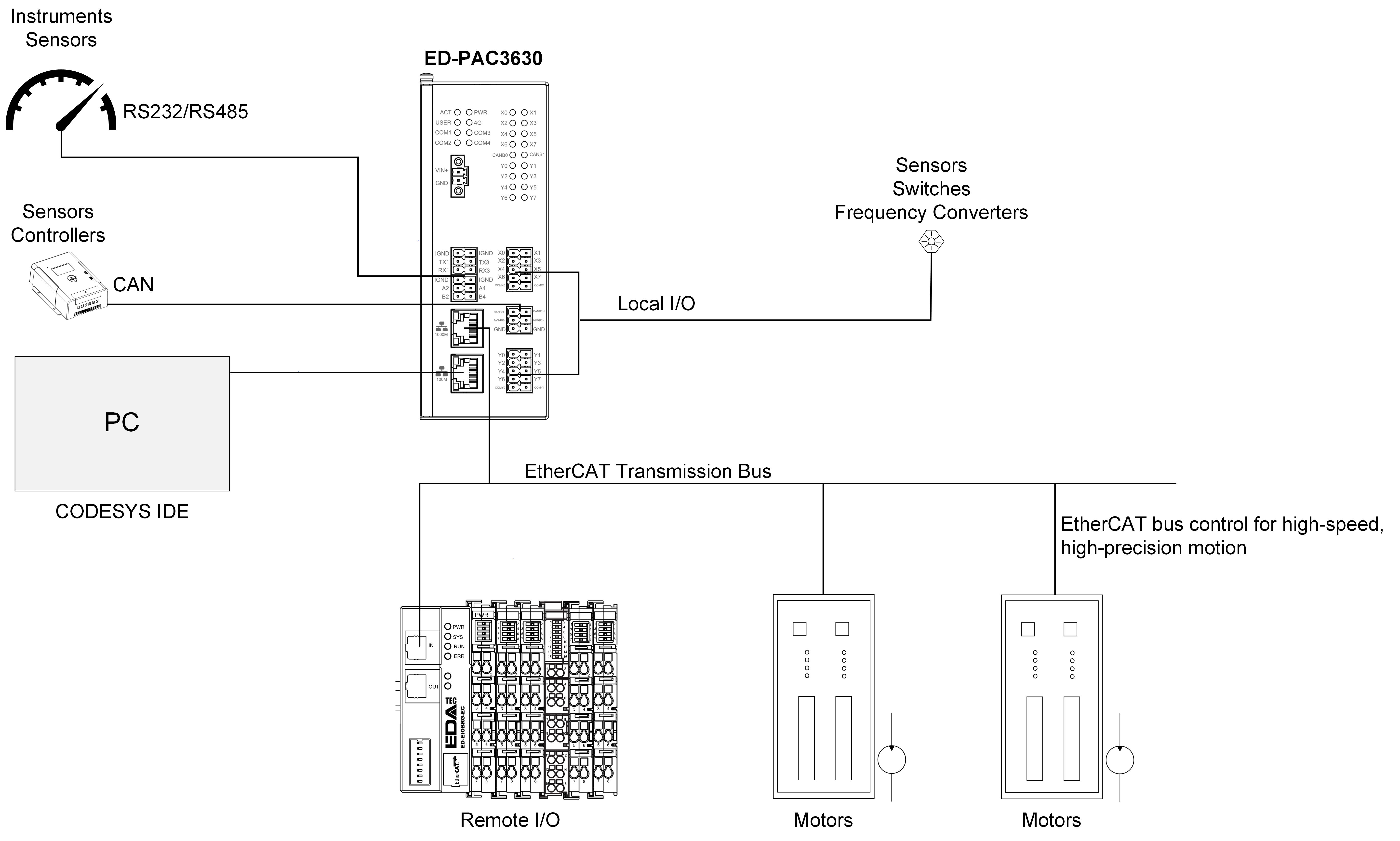
1.3 Networking Application
The ED-PAC3630 features EtherCAT, Ethernet, RS485, RS232, DI, DO, and CAN interfaces, enabling multi-layer network communication to meet diverse application requirements across various scenarios. A typical application topology is illustrated in the figure below:
1.4 Packing List
- 1 x ED-PAC3630 Unit
1.5 Appearance
Introducing the functions and definitions of the interfaces on each panel.
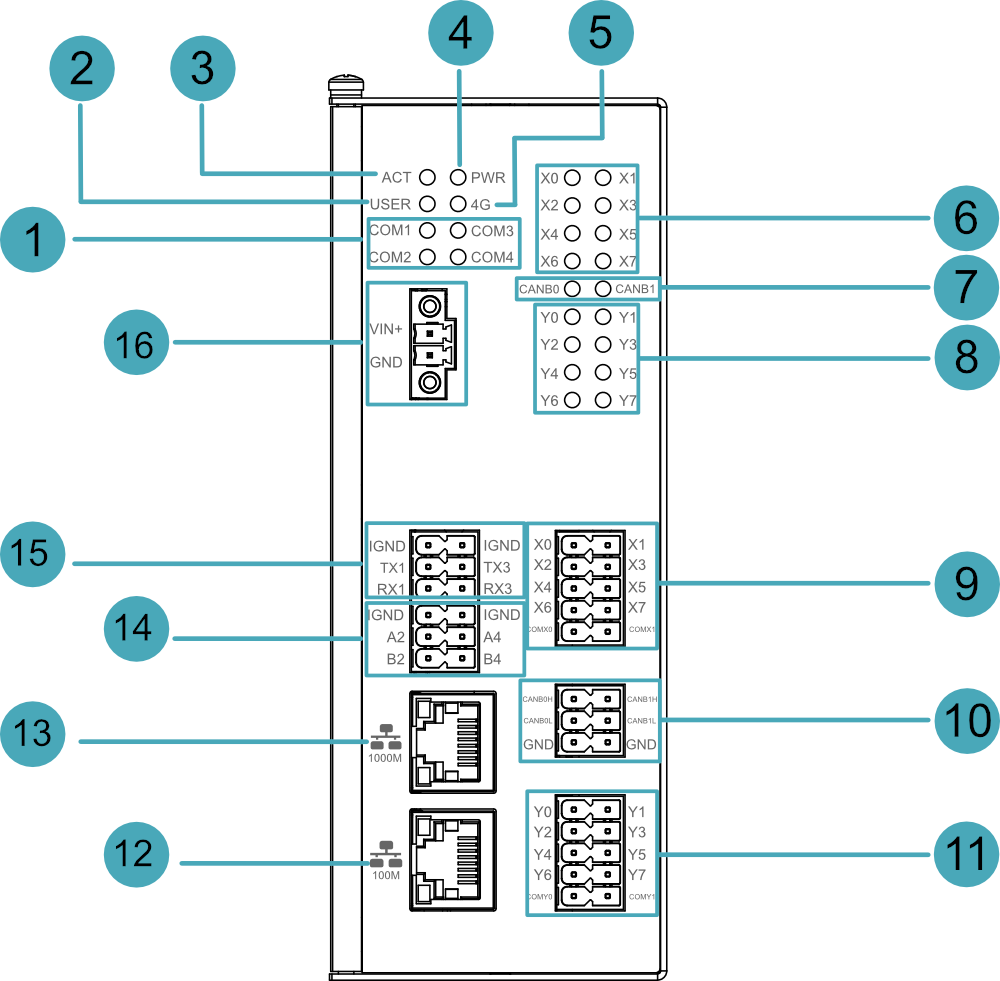
1.5.1 Front Panel
Introducing front panel interface types and definitions.
| NO. | Function Definition |
|---|---|
| 1 | 4 x green UART indicators, which is used to check the communication status of UART port. |
| 2 | 1 x green user indicator, user can customize a status according to actual application. |
| 3 | 1 x green system status indicator, which is used to view the status of system read/write operations. |
| 4 | 1 x red power indicator, which is used to check the status of device power-on and power-off. |
| 5 | 1 x green 4G indicator, reserving location (currently unused). |
| 6 | 8 x green DI indicators, which is used to check the communication status of DI signal. |
| 7 | 2 x green CAN indicators, which is used to check the communication status of CAN signal. |
| 8 | 8 x green DO indicators, which is used to check the communication status of DO signal. |
| 9 | 8 x DI ports, 10-Pin 3.5mm pitch phoenix terminals, which is used to connect third-party sensors. |
| 10 | 2 x CAN ports, 6-Pin 3.5mm pitch phoenix terminals, which is used to connect third-party control equipment. |
| 11 | 8 x DO ports, 10-Pin 3.5mm pitch phoenix terminals, which is used to connect third-party load. |
| 12 | 1 x 10/100M adaptive ethernet port, RJ45 connector, with led indicator. It can be used to access the network. |
| 13 | 1 x 1000M Ethernet port (RJ45), EtherCAT communication interface for connecting to EtherCAT networks. |
| 14 | 2 x RS485 ports, 6-Pin 3.5mm pitch phoenix terminal, which is used to connect the third-party control equipment. |
| 15 | 2 x RS2325 ports, 6-Pin 3.5mm pitch phoenix terminal, which is used to connect the third-party control equipment. |
| 16 | 1 x DC input, 2-Pin 3.5mm pitch phoenix terminals with screw holes. It supports 9V~36V input, the signal is defined as VIN+/GND. |
1.5.2 Rear Panel
Introducing rear panel interface types and definitions.
| NO. | Function Definition |
|---|---|
| 1 | 1 x DIN rail mounting bracket, using to mount the ED-PAC3630 unit onto a DIN rail. |
| 2 | 1 x Micro USB port, it supports to flash to eMMC for the system. Note: The ED-PAC3630 device comes pre-installed with a valid CODESYS license by default. Reinstalling the operating system will invalidate the CODESYS license. Do not attempt to install the OS on your own. |
| 3 | 1 x Nano SIM card slot, reserving for 4G expansion functionality (currently unused). |
| 4 | 1 x Micro SD card slot, it supports the installation of Micro SD card for storing user data. |
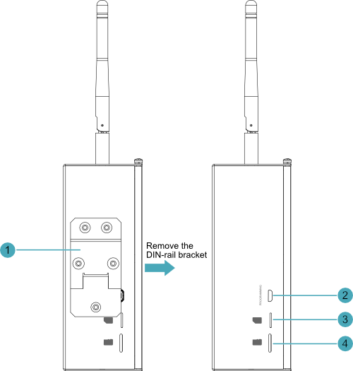
1.5.3 Side Panel
Introducing side panel interface types and definitions.
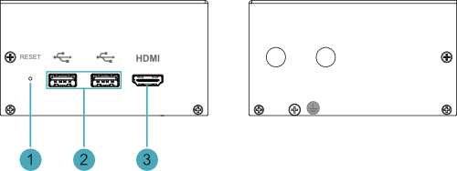
| NO. | Function Definition |
|---|---|
| 1 | 1 x Reset button, hidden button, press the button to restart the device. |
| 2 | 2 x USB 2.0 ports, type A connector, each channel supports up to 480Mbps transmission rate. |
| 3 | 1 x HDMI port, type A connector, which is compatibles with HDMI 2.0 standard and supports 4K 60Hz. It supports to connect a displayer. |
1.6 Button
ED-PAC3630 device includes a RESET button, which is a hidden button, and the silkscreen on the case is "RESET". Pressing the RESET button will reset the device.
1.7 Indicator
This section explains the status and meanings of the indicators integrated into the ED-PAC3630 device.
| Indicator | Status | Description |
|---|---|---|
| PWR | On | The device has been powered on. |
| Blink | Power supply of the device is abnormal, please stop the power supply immediately. | |
| Off | The device is not powered on. | |
| ACT | Blink | The system started successfully and is reading and writing data. |
| Off | The device is not powered on or does not read and write data. | |
| USER | On | User can customize a status according to actual application. |
| Off | The device is not powered on or not defined by the user, and the default status is off. | |
| Yellow indicator of Ethernet port | On | The data transmission is abnormal. |
| Blink | Data is being transmitted over the Ethernet port. | |
| Off | The Ethernet connection is not set up. | |
| Green indicator of Ethernet port | On | The Ethernet connection is in the normal state. |
| Blink | The Ethernet connection is abnormal. | |
| Off | The Ethernet connection is not set up. | |
| COM1~COM4 | On/Blink | Data is being transmitted. |
| Off | The device is not powered on or there is no data transmission. | |
| X0 ~ X7 | On/Blink | The input signal has been detected. |
| Off | The device is not powered on or there is no data transmission. | |
| CANB0 ~ CANB1 | On/Blink | Data is being transmitted. |
| Off | The device is not powered on or there is no data transmission. | |
| Y0 ~ Y7 | On/Blink | The output signal has been detected. |
| Off | The device is not powered on or there is no data transmission. |
1.8 Interface
Introducing the definitions and functions of each interface in the ED-PAC3630.
1.8.1 SD Card Slot
The ED-PAC3630 device includes one Micro SD card slot, labeled as “ ”, supporting installing a Micro SD card for user data storage.
1.8.2 Power Interface
ED-PAC3630 device includes one power input, 2-Pin 3.5mm pitch phoenix terminals with screw holes. The silkscreen of port is “VIN+/GND”, and the pins are defined as follows.
 | Pin ID | Pin Name |
| 1 | GND | |
| 2 | 9V~36V |
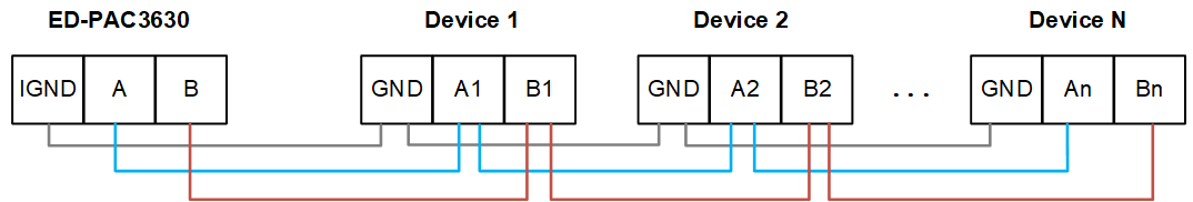
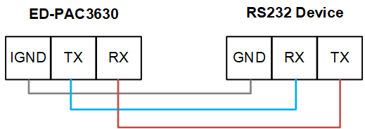
1.8.3 RS485/RS232 Interface
The ED-PAC3630 device includes 2 x RS485 interfaces and 2 x RS232 interfaces.
- Each RS485 interface is labeled "IGND/A/B".
- Each RS232 interface is labeled "IGND/TX/RX".
- Terminal pitch: 3.5mm.
Pin Definition
Terminal pins are defined as follows:
 | Pin ID | Pin Name |
|---|---|---|
| 1 | RS485-2_B | |
| 2 | RS485-4_B | |
| 3 | RS485-2_A | |
| 4 | RS485-4_A | |
| 5 | GND | |
| 6 | GND | |
| 7 | RS232-1_RX | |
| 8 | RS232-3_RX | |
| 9 | RS232-1_TX | |
| 10 | RS232-3_TX | |
| 11 | GND | |
| 12 | GND |
The pin names of the RS485 and RS232 ports corresponding to CM5 are as follows:
| Signal | CM5 GPIO Name | CM5 Pin Out |
|---|---|---|
| RS485-2_B | GPIO13 | UART5_RXD |
| RS485-4_B | GPIO9 | UART4_RXD |
| RS485-2_A | GPIO12 | UART5_TXD |
| RS485-4_A | GPIO8 | UART4_TXD |
| RS232-1_RX | GPIO5 | UART4_RXD |
| RS232-3_RX | GPIO1 | UART2_RXD |
| RS232-1_TX | GPIO4 | UART3_TXD |
| RS232-3_TX | GPIO0 | UART2_TXD |
Connecting Cables
The RS485 wiring schematic is as follows:
The RS232 wiring schematic is as follows:
RS485 Terminating Resistor Configuration
The ED-PAC3630 includes 2 RS485 channels. A 120Ω terminating resistor is pre-installed between the A and B lines of each RS485 channel. Inserting a jumper cap enables this terminating resistor. By default, the jumper cap is not inserted, rendering the 120Ω terminating resistor function disabled.
The locations of the 120Ω terminating resistors on the PCBA (Printed Circuit Board Assembly) and their corresponding COM ports are detailed in the table below.
| Location on PCBA | Corresponding COM Port | Physical Position of COM Port |
|---|---|---|
| J24 | COM4 |  |
| J22 | COM2 |
TIP
The device housing needs to be opened to locate the position of the 120Ω terminating resistor.
1.8.4 DI Interface
The ED-PAC3630 device includes 8 digital input (DI) channels.
- Every 4 DI channels share 1 common terminal (COM):
- X0, X2, X4, X6 → Share COMX0
- X1, X3, X5, X7 → Share COMX1
Terminal pin definitions are as follows:
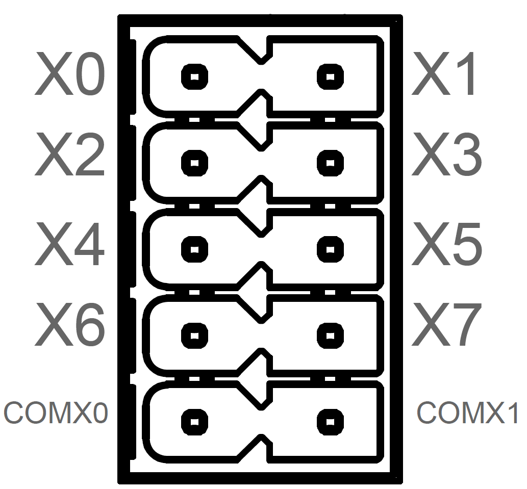 | Pin ID | Pin Name |
| 1 | X0 | |
| 2 | X1 | |
| 3 | X2 | |
| 4 | X3 | |
| 5 | X4 | |
| 6 | X5 | |
| 7 | X6 | |
| 8 | X7 | |
| 9 | COMX0 | |
| 10 | COMX1 |
Connecting Cables
Schematic diagram of a single DI wire is as follows:

| Parameter | Description |
|---|---|
| Input Type | NPN, PNP |
| Isolation Protection | 5kV |
| COM | Every 4 DI share one common pin (called COM):
|
| DI to COM |
|
1.8.5 DO Interface
The ED-PAC3630 device includes 8 digital output (DO) channels.
- Every 4 DO channels share 1 common terminal (COM):
- Y0, Y2, Y4, Y6 → Share COMY0
- Y1, Y3, Y5, Y7 → Share COMY1
Terminal pin definitions are as follows:
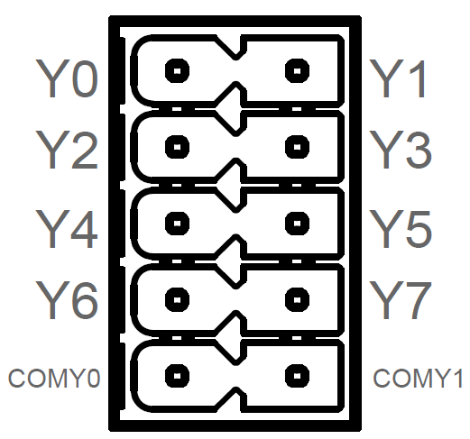 | Pin ID | Pin Name |
| 1 | Y0 | |
| 2 | Y1 | |
| 3 | Y2 | |
| 4 | Y3 | |
| 5 | Y4 | |
| 6 | Y5 | |
| 7 | Y6 | |
| 8 | Y7 | |
| 9 | COMY0 | |
| 10 | COMY1 |
Connecting Cables
Schematic diagram of a single DO wire is as follows:
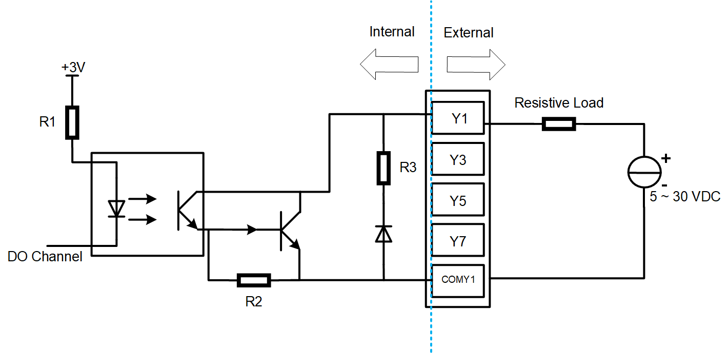
| Parameter | Description |
|---|---|
| Output Type | Transistor |
| Isolation Protection | 5kV |
| COM | Every 4 DI share one common pin (called COM):
|
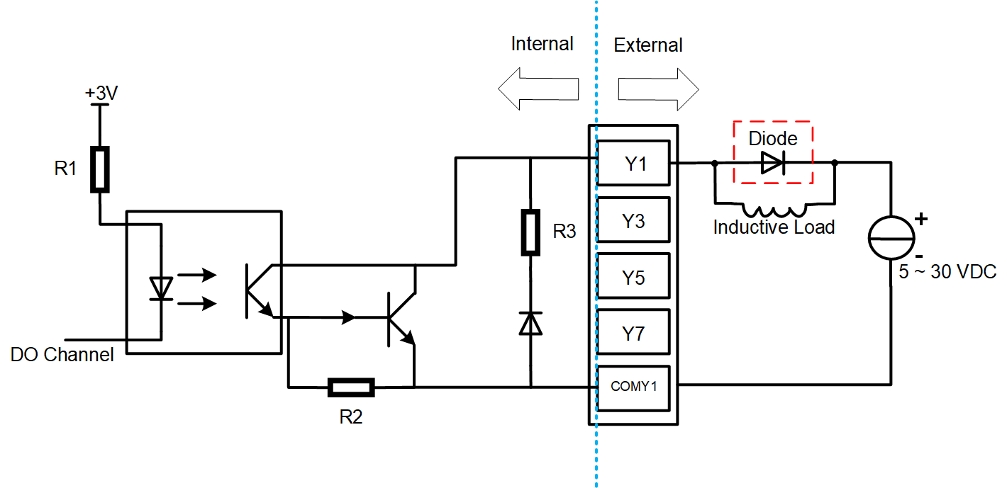
| Output | 5~30 VDC (24 VDC is recommended), maximum current is 1.5A (per channel) |
WARNING
If an inductive load is connected to the DO channel, it is recommended to add a Diode in the circuit (as shown in the figure below) for protection. Select an appropriate Diode based on the specifications of the inductive load.
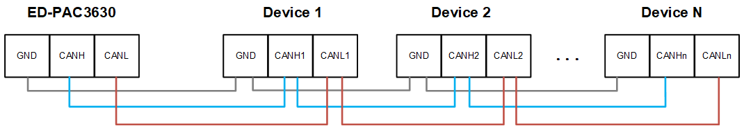
1.8.6 CAN Interface
The ED-PAC3630 device includes 2 channels of CAN interfaces. The terminal pin definitions are as follows:
 | Pin ID | Pin Name |
| 1 | CANB0H | |
| 2 | CANB1H | |
| 3 | CANB0L | |
| 4 | CANB1L | |
| 5 | GND | |
| 6 | GND |
Connecting Cables
Schematic diagram of CAN wires is as follows:
1.8.7 1000M Ethernet Interface (EtherCAT)
The ED-PAC3630 device includes 1 auto-sensing 10/100/1000M Ethernet port, labeled as " ".
".
- Connector type: RJ45.
- Default configuration: EtherCAT communication interface, supporting connection to EtherCAT networks.
- Recommended cable: Category 6 (Cat6) or higher Ethernet cables for optimal performance.
1.8.8 100M Ethernet Interface
The ED-PAC3630 device includes 1 auto-sensing 10/100M Ethernet port, labeled as " ".
".
- Connector type: RJ45.
- Recommended cable: Category 6 (Cat6) or higher Ethernet cables for optimal performance.
1.8.9 HDMI Interface
The ED-PAC3630 device includes 1 HDMI port, labeled as "HDMI", which is a standard Type-A connector. It supports connecting to HDMI displays and delivers video output up to 4K resolution at 60Hz (4K@60Hz).
1.8.10 USB 2.0 Interface
The ED-PAC3630 device includes 2 x USB 2.0 ports, labeled as “ ”, which are standard Type-A connectors. They support to connect USB 2.0 peripherals, the maximum transfer rate is 480Mbps.
1.8.10 Micro USB Interface
The ED-PAC3630 devices include one Micro USB port, labeled as "PROGRAMMING". It is used to connect to a PC for programming the device's eMMC storage.
WARNING
The ED-PAC3630 device comes pre-installed with a valid CODESYS license by default. Reinstalling the operating system will invalidate the CODESYS license. Do not attempt to install the OS on your own.
1.9 Supercapacitor
The ED-PAC3630 supports a supercapacitor backup power module, featuring a comprehensive safe shutdown protection mechanism.
- In the event of an unexpected power failure when the supercapacitor is fully charged, the system can automatically switch to supercapacitor power supply, allowing the device to continue normal operation until the capacitor's charge is depleted. It then automatically shuts down safely, effectively preventing operational interruptions and data loss.
- The device provides user-customizable emergency scripts, supporting pre-configuration of critical data saving, backup, or other emergency procedures. At the moment of power loss, the system will automatically execute the preset scripts to ensure critical operations are completed, allowing for a composed response to sudden power outages.
TIP
- For specific operations on customizing supercapacitor-related parameters, please refer to AN18 Supercapacitor Usage Guide.
- The supercapacitor requires the device to be powered on for at least 5 minutes to fully charge, and normal functionality is only guaranteed when it is fully charged.