1 Hardware Manual
This chapter introduces the product overview, CODESYS software, networking application, packaging list, appearance, buttons, indicators and interfaces.
1.1 Overview
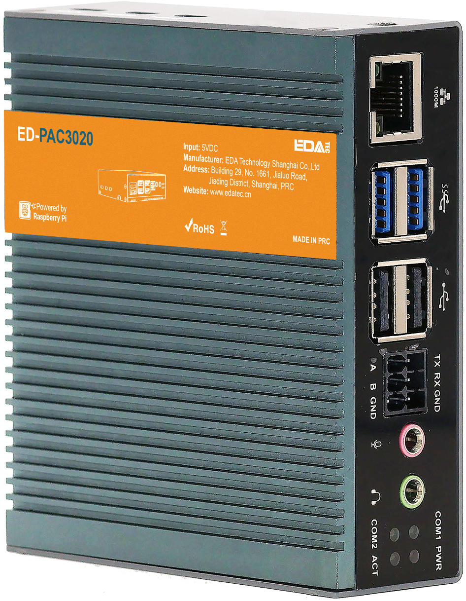
The ED-PAC3020 is a real-time CODESYS programmable automation controller, pre-installed by default with a multi-core CODESYS runtime. Depending on the application scenario and user requirements, it offers programmable logic system configurations with either 2GB DDR + 128GB SSD or 8GB DDR + 256GB SSD.
WARNING
The ED-PAC3020 device comes pre-installed with a valid CODESYS license by default. Reinstalling the operating system will invalidate the CODESYS license. Do not attempt to install the OS on your own.
The ED-PAC3020 provides commonly used interfaces such as HDMI, USB, Ethernet, RS232, and RS485, integrates RTC, and is primarily used in industrial control and IoT fields.
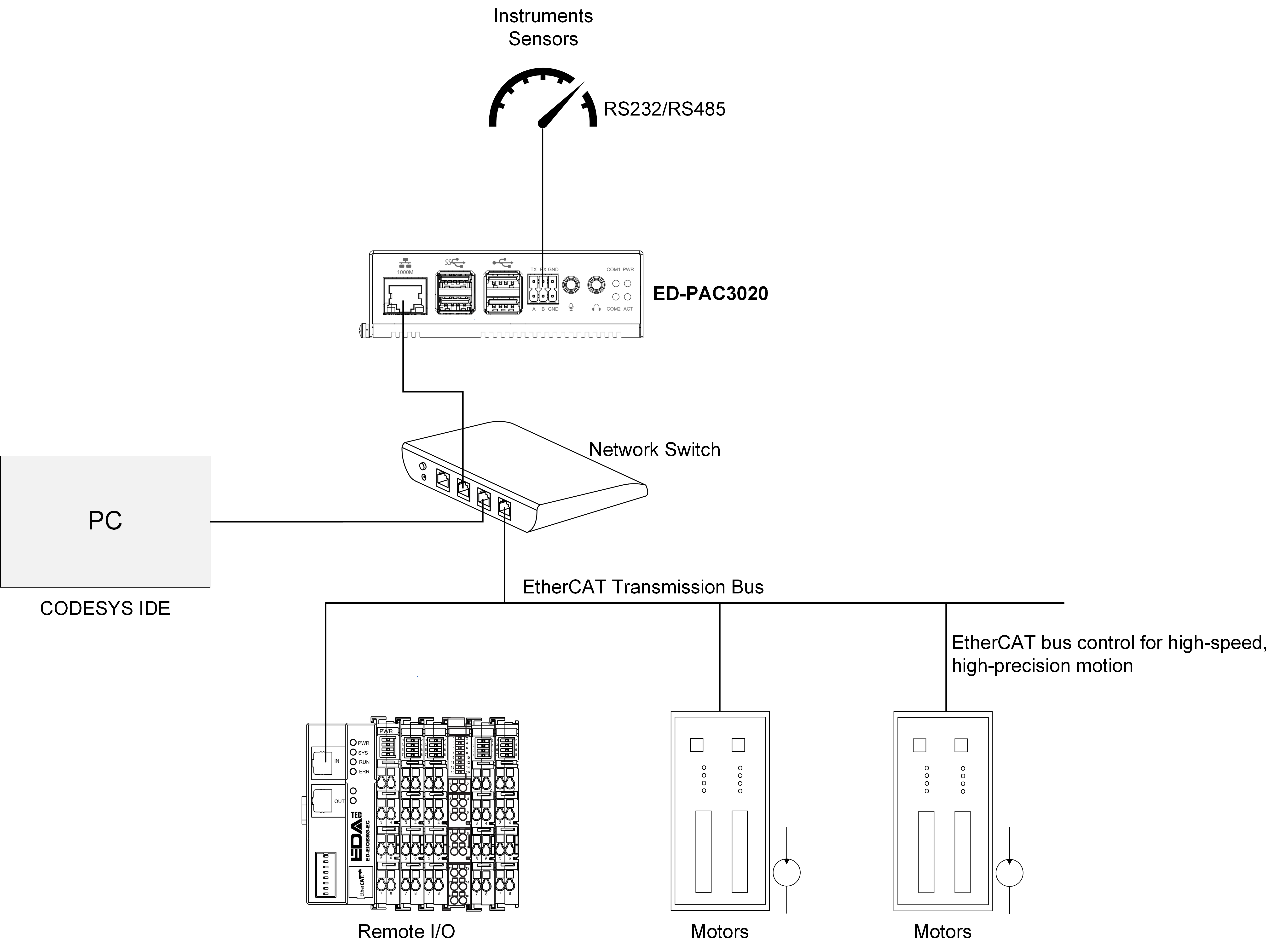
The ED-PAC3020 supports connection to remote EtherCAT-based I/O modules (e.g., couplers, DI, DO, AI, AO) via an EtherCAT network. The device integrates the CODESYS Control Runtime System, supporting IEC 61131-3 programming standards and industrial communication protocols like EtherCAT and Modbus TCP. Users can optionally enable additional functionalities by licensing features such as:
- TargetVisu
- WebVisu
- Softmotion
- CNC + Robotics
- EtherCAT Master
- Modbus TCP Master
- OPC UA Server
Custom configurations are available to meet specific application requirements.
1.2 Introduction to CODESYS Software
CODESYS (Controller Development System) is an open industrial automation software development platform that provides a full-stack solution for programming, debugging, and maintaining programmable logic controllers (PLCs), industrial PCs (IPCs), and embedded control systems. Compliant with the IEC 61131-3 international standard, it supports complex logic control, multi-axis motion control, industrial communication protocol integration, and real-time data processing. It is widely used in smart manufacturing, energy management, logistics automation, and other industrial fields.
Key Features of CODESYS:
- Standardized Programming Language Support
- Full compatibility with the IEC 61131-3 programming languages:
- Ladder Diagram (LD)
- Function Block Diagram (FBD)
- Structured Text (ST)
- Instruction List (IL)
- Sequential Function Chart (SFC)
- Supports Object-Oriented Programming (OOP) extensions for large-scale complex projects.
- Full compatibility with the IEC 61131-3 programming languages:
- Cross-Platform Development & Deployment
- Development Environment: Compatible with Windows and Linux operating systems, offering a unified engineering interface.
- Target Systems: Deployable on 2,000+ industrial controller hardware platforms, including ARM/X86 architectures.
- Modular Engineering Libraries
- Prebuilt Libraries: Include industrial protocol stacks (Modbus/TCP, OPC UA, EtherCAT) and advanced control modules (PID control, CNC interpolation algorithms).
- Custom Libraries: Support encapsulation and reuse of Function Blocks and POUs (Program Organization Units).
- Visual Debugging & Diagnostic Tools
- Real-time monitoring of variables, I/O mapping, and task execution status with waveform analysis.
- Advanced debugging tools: breakpoints, step-by-step execution, and cross-referencing for rapid fault diagnosis.
- Integrated HMI development tools for seamless SCADA system integration.
The ED-PAC3020 supports CODESYS V3.5 SP19 and later versions.
1.3 Networking Application
The ED-PAC3020 features EtherCAT, Ethernet, RS485 and RS232 interfaces, enabling multi-layer network communication to meet diverse application requirements across various scenarios. A typical application topology is illustrated in the figure below:
1.4 Packing List
- 1 x ED-PAC3020 Unit
- 4 x Pads
1.5 Appearance
Introducing the functions and definitions of the interfaces on each panel
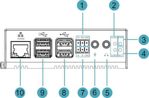
1.5.1 Front Panel
Introducing front panel interface types and definitions.
| NO. | Function Definition |
|---|---|
| 1 | 1 x RS232 port, 3-Pin 3.5mm pitch phoenix terminal, which is used to connect the third-party control equipment. |
| 2 | 2 x green UART indicators, which is used to check the communication status of UART port. |
| 3 | 1 x red power indicator, which is used to check the status of device power-on and power-off. |
| 4 | 1 x green system status indicator, which is used to view the status of system read/write operations. |
| 5 | 1 x Audio Output (HPO), 3.5mm audio jack connector (green), stereo audio output. |
| 6 | 1 x Audio Input (LINE IN), 3.5mm audio jack connector (red), supporting stereo audio input. |
| 7 | 1 x RS485 port, 3-Pin 3.5mm pitch phoenix terminal, which is used to connect the third-party control equipment. |
| 8 | 2 x USB 2.0 ports, Type-A connector, each channel supports up to 480Mbps transmission rate. |
| 9 | 2 x USB 3.0 ports, Type-A connector, each channel supports up to 5Gbps transmission rate. |
| 10 | 1 x Ethernet interface (10/100/1000M auto-negotiation), RJ45 connector, EtherCAT communication interface for connecting to EtherCAT networks, with PoE (Power over Ethernet) support. |
1.5.2 Rear Panel
Introducing rear panel interface types and definitions.

| NO. | Function Definition |
|---|---|
| 1 | 1 x power button, which is used to turn on and turn off the device. |
| 2 | 1 x Micro SD card slot, reserved for future use. Note: The device boots from the SSD by default. This Micro SD card slot is reserved for potential expansion. |
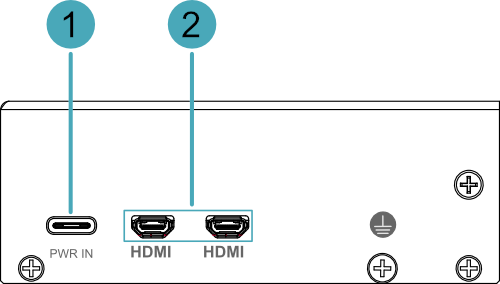
1.5.3 Side Panel
Introducing side panel interface types and definitions.
| NO. | Function Definition |
|---|---|
| 1 | 1 x DC input, USB Type-C connector, which supports 5V 5A power input. |
| 2 | 2 x HDMI ports, Micro HDMI connector, which can connect a display and supports 4K 60Hz |
1.6 Button
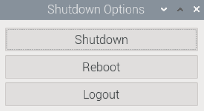
The ED-PAC3020 includes a ON/OFF button, and the silkscreen is "ON/OFF". If you run Raspberry Pi Desktop, you can initiate a clean shutdown by briefly pressing the power button. A menu will appear asking whether you want to shutdown, reboot, or logout:
TIP
If you run Raspberry Pi Desktop, you can press the power button twice in quick succession to shut down.
1.7 Indicator
This section explains the status and meanings of the indicators integrated into the ED-PAC3020 device.
| Indicator | Status | Description |
|---|---|---|
| PWR | On | The device has been powered on. |
| Blink | Power supply of the device is abnormal, please stop the power supply immediately. | |
| Off | The device is not powered on. | |
| ACT | Blink | The system started successfully and is reading and writing data. |
| Off | The device is not powered on or does not read and write data. | |
| COM1~COM2 | On/Blink | Data is being transmitted |
| Off | The device is not powered on or there is no data transmission. | |
| Yellow indicator of Ethernet port | On | The Ethernet connection is in the normal state. |
| Blink | The Ethernet connection is abnormal. | |
| Off | The Ethernet connection is not set up. | |
| Green indicator of Ethernet port | On | The Ethernet connection is in the normal state. |
| Blink | Data is being transmitted over the Ethernet port. | |
| Off | The Ethernet connection is not set up. |
TIP
The function of the PWR/ACT indicator on the Raspberry Pi 5 has been transferred to the separate PWR and ACT indicators by default, so the PWR/ACT indicator remains on after the device is powered on.
1.8 Interface
Introducing the definition and function of each interface in the product.
1.8.1 Power Interface
The ED-PAC3020 device includes one power input interface, which utilizes a USB Type-C connector labeled "PWR IN" and supports a 5V 5A power input.
TIP
In order for Raspberry Pi 5 to achieve better performance, it is recommended to use a 5V 5A power adapter.
1.8.2 1000M Ethernet Interface (EtherCAT)
The ED-PAC3020 device includes one auto-negotiating 10/100/1000M Ethernet interface with an RJ45 connector featuring status LEDs, labeled as " ". This interface serves as an EtherCAT communication port for connecting to EtherCAT networks and supports PoE (Power over Ethernet) power delivery.
1.8.3 HDMI Interface
The ED-PAC3020 device includes 2 HDMI interfaces using Micro HDMI connectors, labeled "HDMI", for connecting HDMI displays. These interfaces support video output up to 4Kp60.
TIP
Some third-party Micro HDMI cables may have shorter Micro HDMI connectors, which could cause connection issues. It is recommended to use the official Raspberry Pi Micro HDMI to Standard HDMI cable for optimal compatibility.
1.8.4 USB 2.0 Interface
The ED-PAC3020 device includes 2 USB 2.0 interfaces with standard Type-A connectors, labeled as " ". These interfaces support connecting standard USB 2.0 peripherals and offer a maximum transfer rate of 480Mbps.
1.8.5 USB 3.0 Interface
The ED-PAC3020 device includes 2 USB 3.0 interfaces with standard Type-A connectors, labeled as " ". These interfaces support connecting standard USB 3.0 peripherals and offer a maximum transfer rate of 5Gbps.
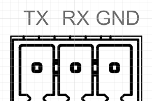
1.8.6 RS232 Interface
The ED-PAC3020 device includes 1 RS232 interface with a 3-Pin 3.5mm pitch Phoenix terminal, labeled "TX/RX/GND".
Pin Definition
Terminal pins are defined as follows:
 | Pin ID | Pin Name |
|---|---|---|
| 1 | TX | |
| 2 | RX | |
| 3 | GND |
The RS232 interface corresponds to the following pin names on the Pi5:
| Signal | Pi5 GPIO Name | Pi5 Pin Out |
|---|---|---|
| TX | GPIO4 | UART3_TXD |
| RX | GPIO5 | UART3_RXD |
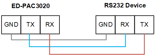
Connecting Cables
The RS232 wiring schematic is as follows:
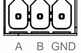
1.8.7 RS485 Interface
The ED-PAC3020 device includes 1 RS485 interface with a 3-Pin 3.5mm pitch Phoenix terminal, labeled "A/B/GND".
Pin Definition
Terminal pins are defined as follows:
 | Pin ID | Pin Name |
|---|---|---|
| 1 | A | |
| 2 | B | |
| 3 | GND |
The RS485 interface corresponds to the following pin names on the Pi5:
| Signal | Pi5 GPIO Name | Pi5 Pin Out |
|---|---|---|
| A | GPIO12 | UART5_TXD |
| B | GPIO13 | UART5_RXD |
Connecting Cables
The RS485 wiring schematic is as follows:
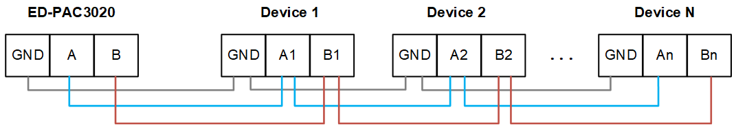
RS485 Terminating Resistor Configuration
The ED-PAC3020 device includes 1 RS485 interface. A 120Ω termination resistor is reserved between the A and B lines of the RS485 circuit. Inserting a jumper cap enables this termination resistor. By default, no jumper is installed, rendering the 120Ω termination resistor inactive. The termination resistor is located at J7 on the PCBA (printed circuit board assembly).
TIP
The device case must be opened to inspect the 120Ω termination resistor.
1.8.8 Audio Input
The ED-PAC3020 device includes 1 audio input interface (LINE IN), a red 3.5mm audio jack, labeled as " ", which supports stereo input.
1.8.9 Audio Output
The ED-PAC3020 device includes 1 audio output interface (HPO), a green 3.5mm audio jack, labeled as " ", which supports stereo output.