2 Installing Components (optional)
This chapter describes how to install optional components.
2.1 Installing Internal Components
Introducing the detailed operations of opening/closing the device casing and installing the RTC battery. Before installing the internal components, it is necessary to open the device case.
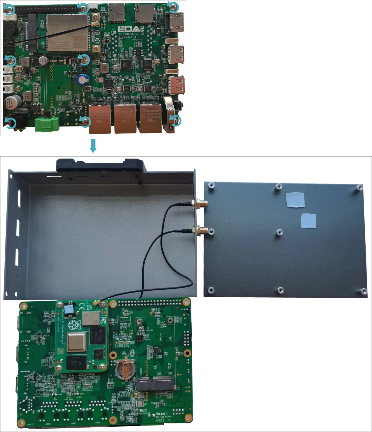
2.1.1 Open Device Case
Preparation:
A cross screwdriver has been prepared.
Steps
Pull out the default configuration of phoenix connector (male for wiring).
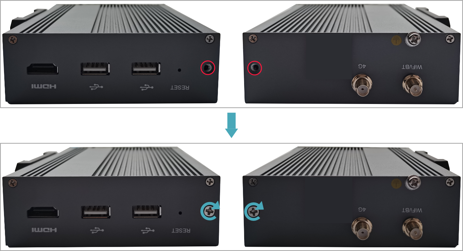
Use a screwdriver to loosen two M3 screws on two sides counterclockwise.
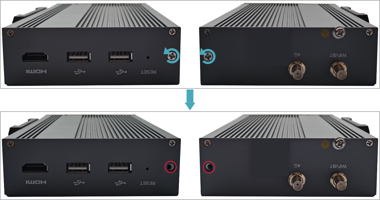
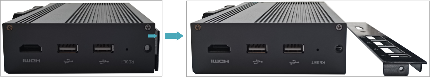
- Remove the front cover to the right.
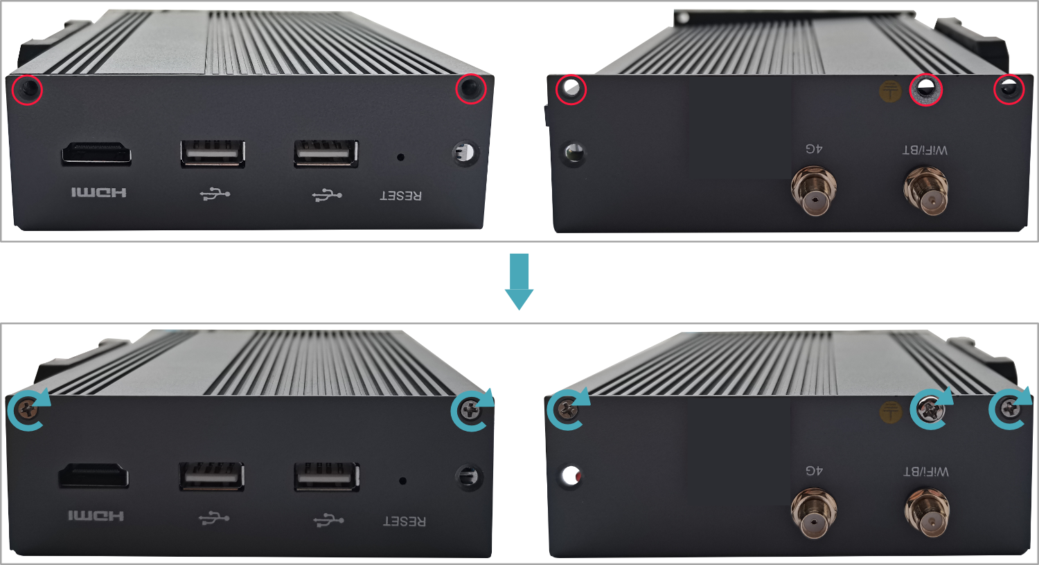
- Use a screwdriver to loosen four M2.5 screws and one grounding screw on two sides counterclockwise.
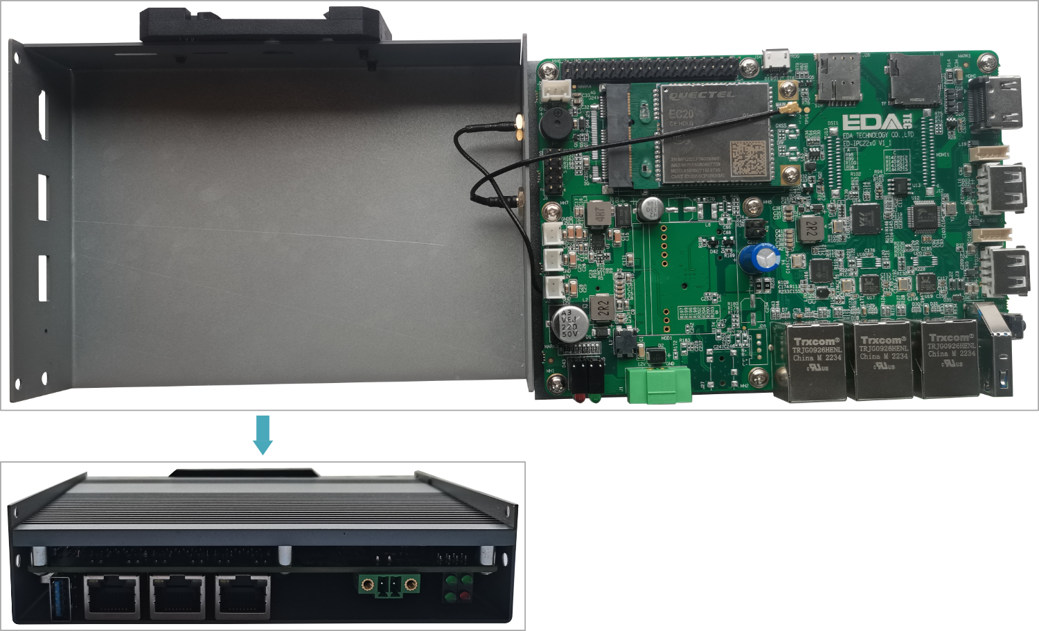
- Remove the upper cover upward and turn it to the antenna port side.
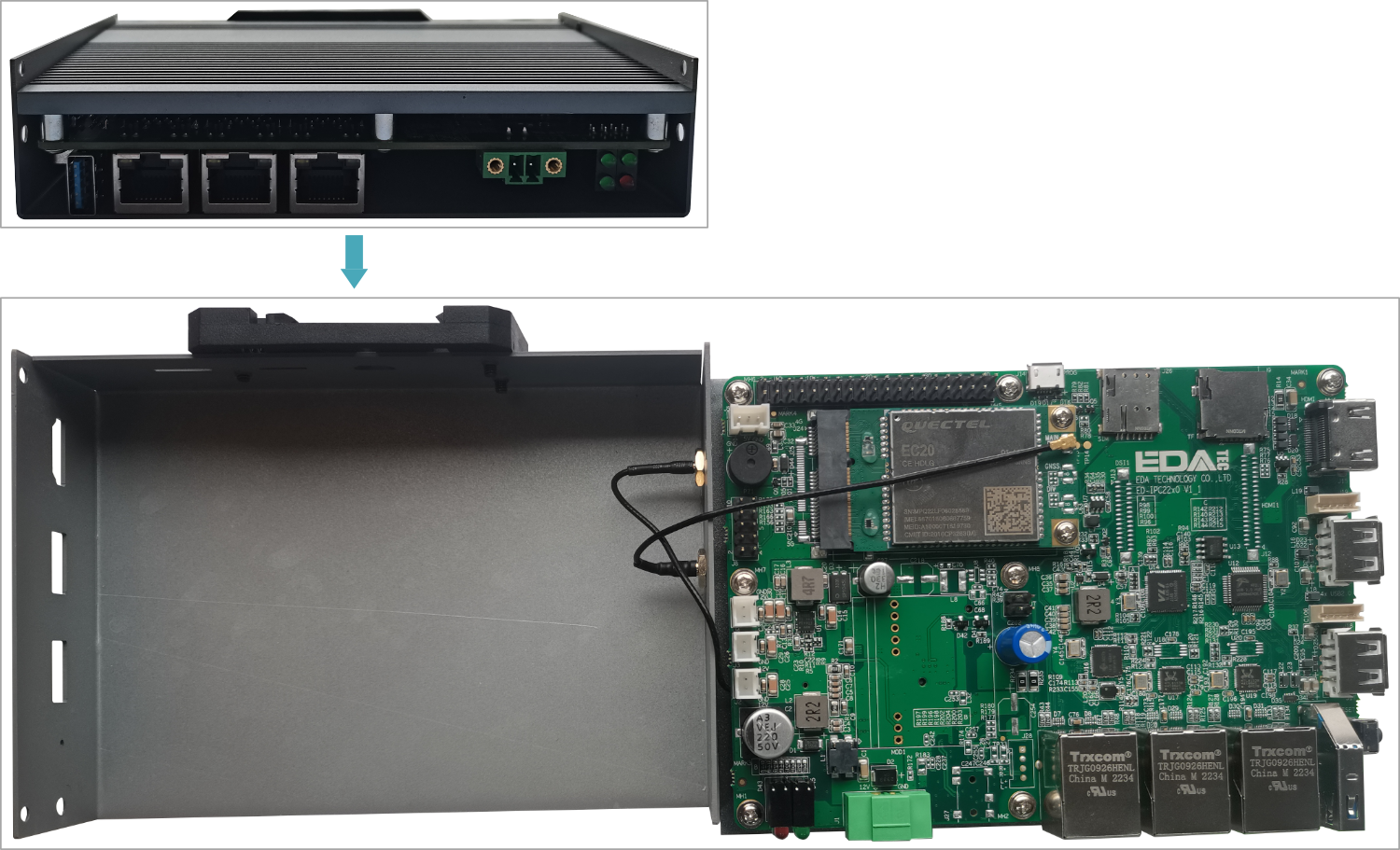
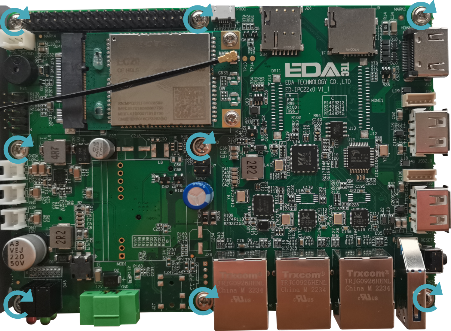
- Use a screwdriver to loosen the 8 screws fixing the PCBA counterclockwise, remove the upper cover and flip it to the back of the PCBA.
2.1.2 Install RTC battery
TIP
Some international logistics do not support the transportation of batteries, and some ex-factory not equipped with CR1220 batterie. Therefore, before using RTC, please prepare a CR1220 battery and install it on the motherboard.
Preparation:
- The device case has been opened.
- The CR1220 battery has been prepared.
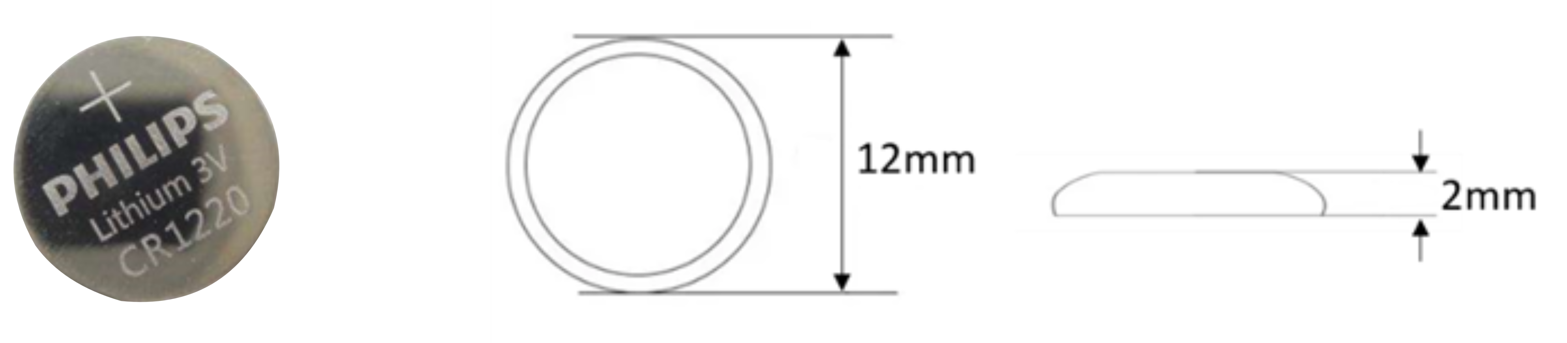
Steps:
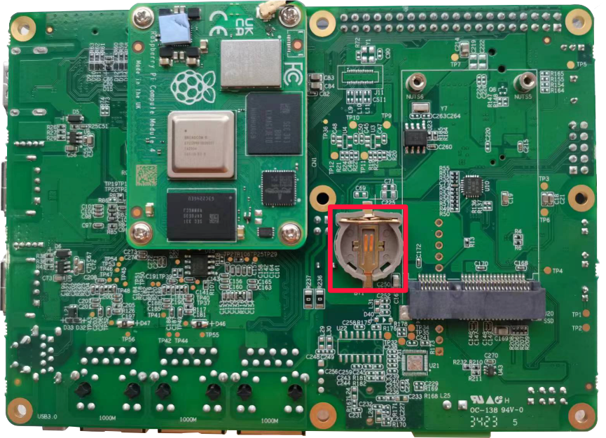
- Locate the RTC battery base where the battery is to be installed, as shown in the red box below.
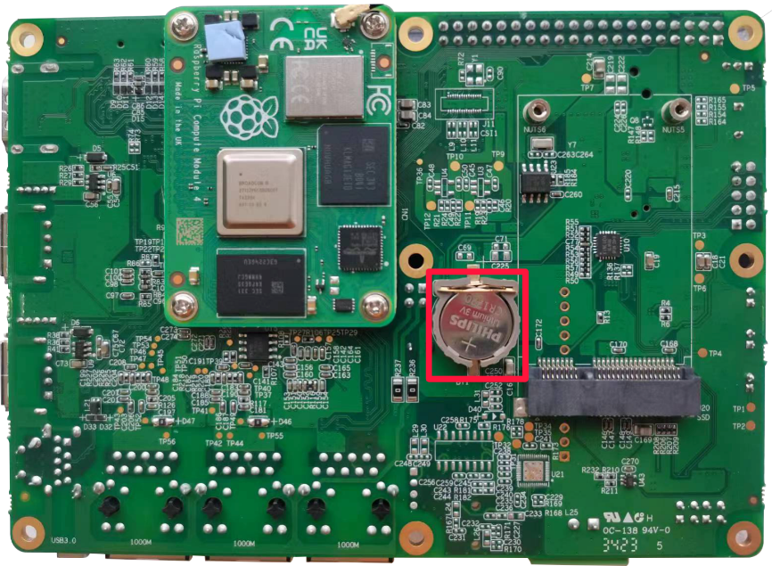
- Put the positive pole of the battery upwards and press it into the RTC base. The installation effect is as shown below.
2.1.3 Close Device Case
Preparation:
A cross screwdriver has been prepared.
Steps:
- Turn the PCBA over to the front and place it on the upper cover, align the 8 screw holes on the PCBA with the stud holes in the upper cover, insert the 8 mounting screws, and then use a screwdriver to tighten clockwise to fix the PCBA on the on the upper cover.
- Turn the upper cover downwards, align the ports on PCBA with the ports on each side panel and close the upper cover.
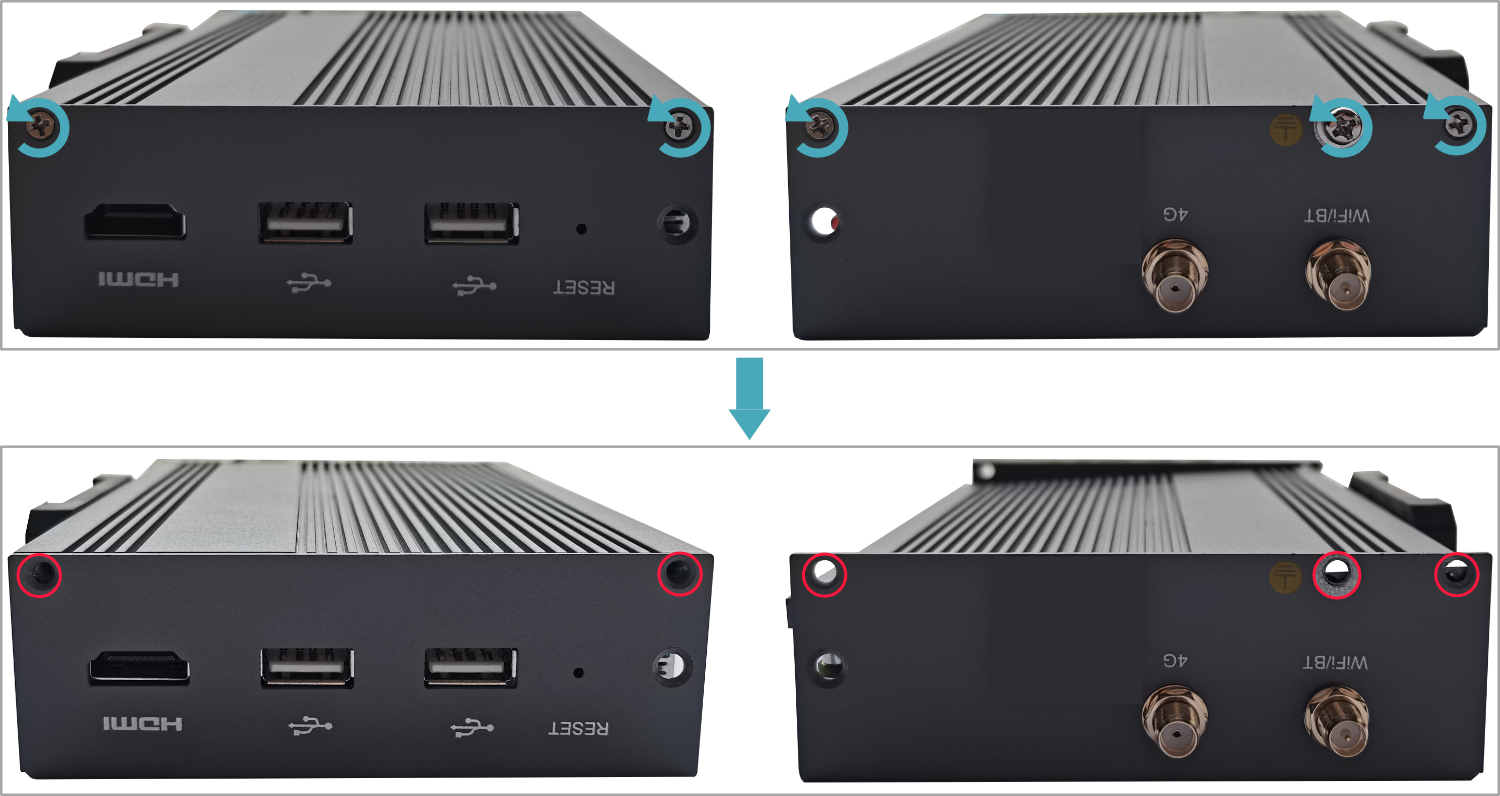
- Align the screw holes on the upper and side panels and use a screwdriver to tighten four M2.5 screws and one grounding screw on two sides clockwise.
- Align the ports on PCBA with the ports on the front panel, insert the front cover.
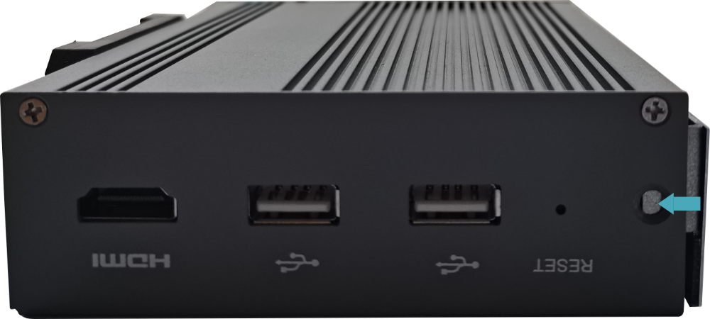
- Insert 2 M3 screws and then use a screwdriver to fasten two M3 screws clockwise.
- Plug in the default phoenix connector.
2.2 Installing/Removing External Components
Introducing the detailed operations of installing/removing some optional accessories.
2.2.1 Install Antenna
If the purchasing ED-IPC2200 series device includes 4G and Wi-Fi functions, the antenna need to be installed before using the device.
Preparation:
The corresponding antennas have been obtained from the packaging box. If there are multiple antennas, they can be distinguished by the labels on the antennas.
Steps:
- Find the location of antenna port, as shown in the red mark of figure below.
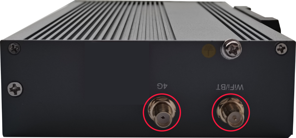
- Align the ports on both sides of the device and the antenna and tighten them clockwise to ensure that they will not fall off.
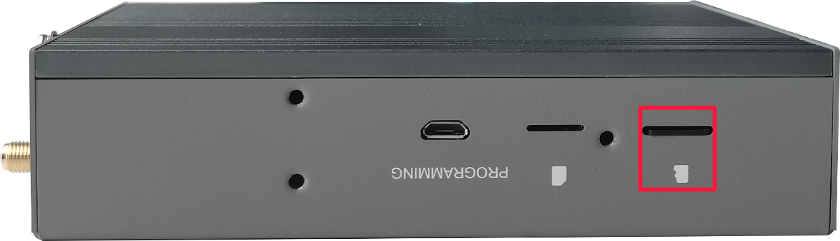
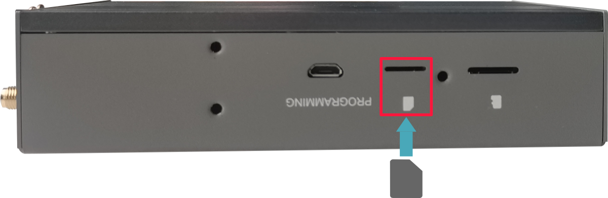
2.2.2 Install Micro SD Card
If the product model includes a Micro SD card, the Micro SD card will be installed by default. If the product model does not include a Micro SD card, you will need to use the Micro SD card later. Please refer to the following to install it.
WARNING
Please turn off the power before inserting or removing the Micro SD card.
Preparation:
- Micro SD card is ready.
- The device has been disconnected from power.
Steps:
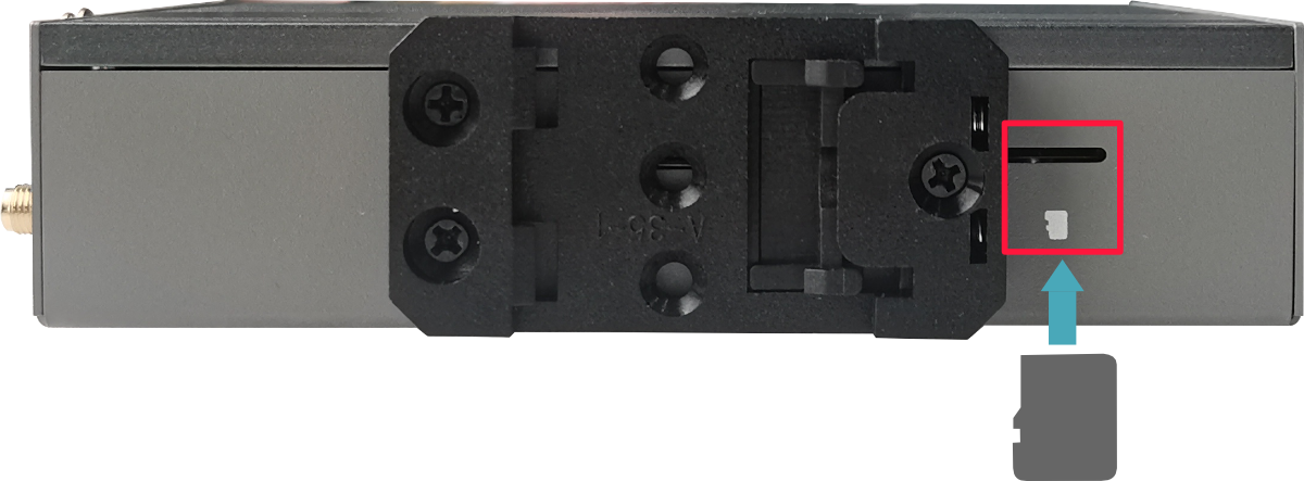
- Find the location of Micro SD card slot, as shown in the red mark of figure below.
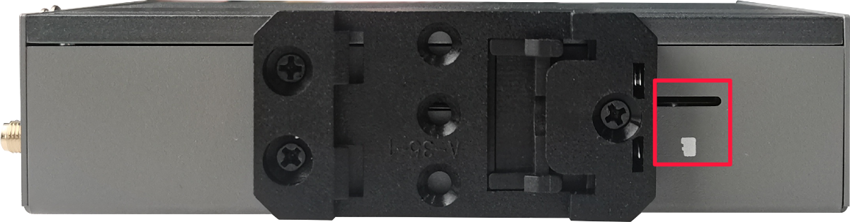
- Insert the Micro SD card into the corresponding card slot with the contact side facing down, and hear a sound to indicate that the installation is completed.
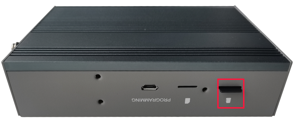
2.2.3 Pull Out Micro SD Card
If you need to remove the Micro SD card while using the product, you can refer to the following instructions.
Preparation:
The device has been disconnected from power.
Steps:
- Find the location of Micro SD card, as shown in the red mark of figure below.
- Press the Micro SD card into the card slot with your hand to pop it out, and then pull out the Micro SD card.
2.2.4 Install Nano SIM Card
If the purchasing ED-IPC2200 series device includes 4G function, the Nano SIM card need to be installed before using 4G.
Preparation:
The 4G Nano SIM card is ready.
Steps:
- Use a cross screwdriver to loosen three screws on the DIN-rail bracket counterclockwise and remove the default DIN-Rail bracket.
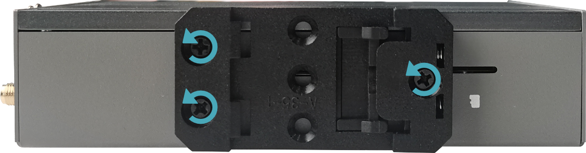
- Find the location of Nano SIM card slot, as shown in the red mark of figure below.
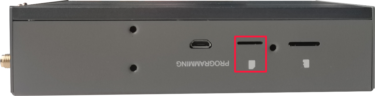
- Insert the Nano SIM card into the corresponding card slot with the chip side up, and hear a sound to indicate that the installation is completed.
- Install the DIN-Rail bracket onto the device case.