1 Hardware Manual
This chapter introduces the product overview, packing list, appearance, button, indicator, and interface.
1.1 Overview
The ED-IPC1100 is an industrial computer based on the Raspberry Pi CM0, featuring 512MB of RAM as standard with optional 8GB or 16GB eMMC storage. It provides common interfaces such as HDMI, USB, Ethernet, and RS485, and supports network connectivity via Wi-Fi, Ethernet, and 4G. Integrated with an RTC, it is primarily designed for industrial control and IoT applications.

1.2 Packing List
- 1 x ED-IPC1100 Unit
- 1 x 2.4GHz Wi-Fi/BT Antenna
- 1 x 4G Antenna
- 1 x 3-Pin Phoenix Terminal
1.3 Appearance
Introduce the functions and definitions of the interfaces on each panel.
1.3.1 Front Panel
Introduce the types and definitions of the front panel interfaces.

| NO. | Function Definition |
|---|---|
| 1 | 1 x power indicator, red, used to display the device's power on/off status. |
| 2 | 1 x system status indicator, green, used to monitor the device's operating status. |
| 3 | 1 x RS485 indicator, green, used to display the communication status of the RS485 serial port. |
| 4 | 1 x 4G signal indicator, green, for checking the status of the 4G signal. |
| 5 | 2 x User indicators, green, allowing users to customize the status based on actual needs. |
| 6 | 1 x DC input, DC jack connector, supports 9V~28V input. |
| 7 | 1 x HDMI port, Type-A connector, compliant with HDMI 1.3a standard, supports 1080p resolution at 30Hz. |
| 8 | 1 x adaptive 10M/100M ethernet port, RJ45 connector. It can be used to access the network. |
1.3.2 Rear Panel
Introducing the types and definitions of the rear panel interface.

| NO. | Function Definition |
|---|---|
| 1 | 1 x Rail mounting bracket, used to install the ED-IPC1100 unit on a DIN rail via the bracket. |
| 2 | 1 x Nano SIM card slot for installing a Nano SIM card to obtain 4G signal. |
| 3 | 1 x Micro SD card slot, supports installation of a Micro SD card for system boot. Note: The system supports booting from a Micro SD card only when the ED-IPC1100 is equipped with a CM0Lite. |
| 4 | 1 x Type-C USB interface, supports eMMC flashing via this interface. |
1.3.3 Side Panel
Introducing the types and definitions of side panel interfaces.
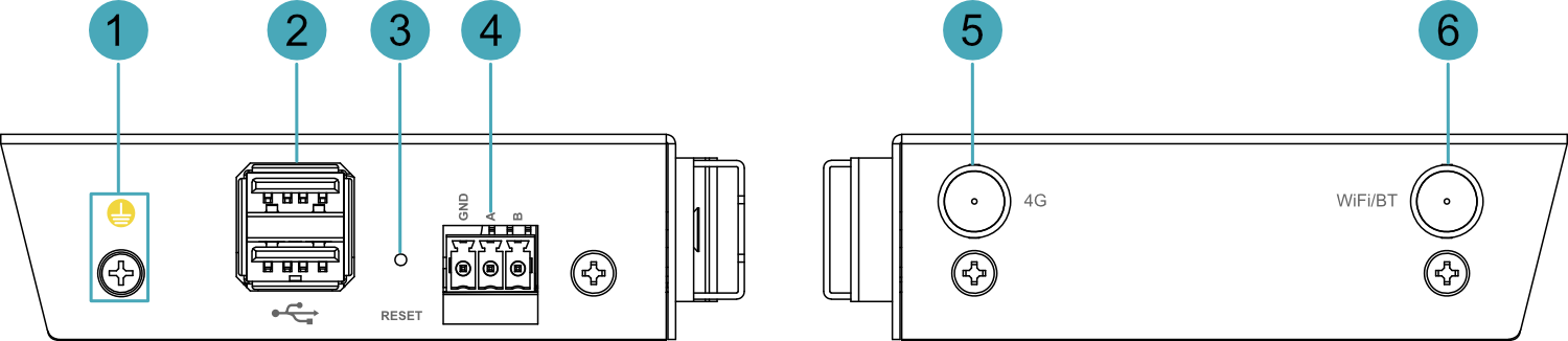
| NO. | Function Definition |
|---|---|
| 1 | 1 x Grounding point, for connecting to the earth ground of an external power supply. |
| 2 | 2 x USB 2.0 ports, stacked Type-A connector, each supporting a maximum data transfer rate of 480Mbps. |
| 3 | 1 x reset button, recessed design, pressing the button restarts the device. |
| 4 | 1 x RS485 interface, 3-pin 3.5mm pitch phoenix terminal, signal definitions: GND/A/B. |
| 5 | 1 x Antenna interface, SMA connector, for connecting 4G antenna |
| 6 | 1 x Antenna interface, SMA connector, for connecting Wi-Fi/BT antenna |
1.4 Button
The ED-IPC1100 device includes one RESET button, which is a recessed button marked with "RESET" on the casing silkscreen. Pressing the RESET button reboots the device.
1.5 Indicator
Introduce the various states and meanings of the indicator included in the ED-IPC1100.
| Indicator | Status | Description |
|---|---|---|
| PWR | On | The device has been powered on. |
| Blink | Power supply of the device is abnormal, please stop the power supply immediately. | |
| Off | The device is not powered on. | |
| ACT | Blink | The system started successfully and is reading and writing data. |
| Off | The device is not powered on or does not read and write data. | |
| USER1 and USER2 | On | User-defined |
| Off | The device is not powered on or is not user-defined. The default state is off. | |
| 4G | On | Dial-up successful, connection established. |
| Off | The 4G signal is not connected or the device is not powered on. | |
| Green indicatorof Ethernet port | On | The Ethernet connection is abnormal. |
| Blink | Data is being transmitted over the Ethernet port. | |
| Off | The Ethernet connection is not set up. | |
| Yellow indicatorof Ethernet port | On | The Ethernet connection is in the normal state. |
| Blink | The Ethernet connection is abnormal. | |
| Off | The Ethernet connection is not set up. | |
| RS485 | On/Blink | Data is being transmitted. |
| Off | The device is not powered on or there is no data transmission. |
1.6 Interface
Introduce the definitions and functions of the various interfaces in the product.
1.6.1 Card Slot
ED-IPC1100 includes a Micro SD card slot and a Nano SIM card slot.
1.6.1.1 Micro SD Card Slot
The silkscreen on the case of Micro SD card slot is "  "". It supports the installation of a Micro SD card to boot the system.
TIP
- Booting from a Micro SD card is supported only when the ED-IPC1100 is equipped with a CM0Lite.
- When the ED-IPC1100 uses a CM0 with 8GB or 16GB eMMC, the Micro SD card slot is a non-functional interface.
1.6.1.2 Nano SIM Card Slot
The silkscreen on the case of Nano SIM card slot is " ", and is used to install a Nano SIM card for obtaining a 4G signal.
1.6.2 Power Interface
The ED-IPC1100 device features one power input interface using a DC Jack connector, with the interface silkscreened as "DC IN". It supports a power input range of 9V to 28V.
1.6.3 RS485 Interface
The ED-IPC1100 device includes one RS485 interface using a 3-pin 3.5mm pitch Phoenix terminal connector, silkscreened as "GND/A/B", which supports connection with third-party controllers.
Pin Definition
Terminal pins are defined as follows:
 | Pin ID | Pin Name |
|---|---|---|
| 1 | GND | |
| 2 | RS485-A | |
| 3 | RS485-B |
The pin names corresponding to the RS485 interface on the CM0 are as follows:
| Signal | CM0 Pin Out |
|---|---|
| RS485-A | GPIO14 |
| RS485-B | GPIO15 |
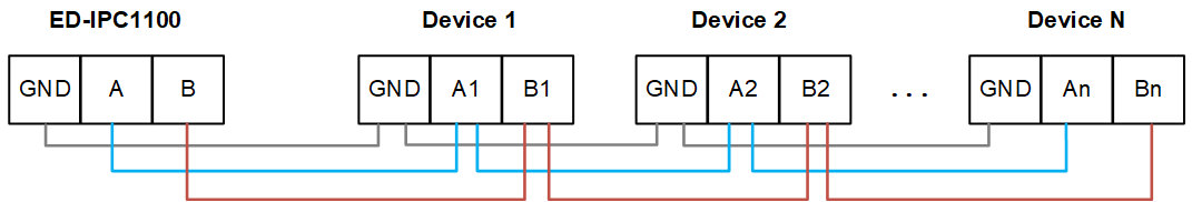
Connecting Cables
Schematic diagram of RS485 wires is as follows:
RS485 Terminal Resistance Configuration
The ED-IPC1100 device includes one RS485 interface with a pre-installed 120Ω termination resistor between the A and B lines of the RS485 circuit. Inserting a jumper cap enables this termination resistor. By default, the jumper cap is not installed, rendering the 120Ω termination function inactive. The location of the termination resistor on the PCBA is marked as J10.
TIP
Opening the device case is required to access the location of the 120Ω termination resistor.
1.6.4 100M Ethernet Interface
The ED-IPC1000 device includes one adaptive 10/100M Ethernet interface, with the interface silkscreened as " ". It uses an RJ45 connector, and when connecting to Ethernet, it is recommended to use a network cable of Cat6 or above specification. The pin definitions corresponding to the connector are as follows:
 | Pin ID | Pin Name |
|---|---|---|
| 1 | TX+ | |
| 2 | TX- | |
| 3 | Rx+ | |
| 4 | - | |
| 5 | - | |
| 6 | RX- | |
| 7 | - | |
| 8 | - |
1.6.5 HDMI Interface
The ED-IPC1100 device includes one HDMI interface, silkscreened as "HDMI", which is a standard Type-A connector. It is compatible with HDMI displays and supports video output of up to 1080p30.
1.6.6 USB 2.0 Interface
The ED-IPC1100 device includes two USB 2.0 interfaces, silkscreened as " ", which are standard dual-layer Type-A connectors. They support connection with standard USB 2.0 peripherals and offer a maximum transmission rate of 480 Mbps.
1.6.7 Type-C USB Interface
The ED-IPC1100 device includes one Type-C USB interface, silkscreened as "PROGRAMMING", which supports flashing the device's eMMC by connecting to a PC.
1.6.8 Antenna Interface
The ED-IPC1100 device includes two SMA antenna interfaces, silkscreened as "4G" and "WiFi/BT" respectively, which are used to connect the 4G antenna and the Wi-Fi/BT antenna accordingly.