1 Hardware Manual
This chapter introduces the product overview, packing list, appearance, button, indicators and interfaces.
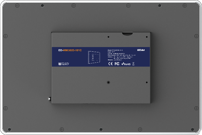
1.1 Overview
ED-HMI3020-101C is a 10.1-inch industrial HMI based on Raspberry Pi 5. According to different application scenarios and user needs, different specifications of RAM, SD card and SSD can be selected.
- RAM can choose 2GB, 4GB, 8GB and 16GB
- SD card can choose 32GB and 64GB
- SSD can choose 128GB and 256GB
ED-HMI3020-101C provides HDMI, USB 2.0, USB 3.0, RS232, RS485, Audio and Ethernet interfaces, supporting access to the network through Wi-Fi and Ethernet. ED-HMI3020-101C integrates RTC and is mainly used in industrial control and IOT.

1.2 Packing List
- 1x ED-HMI3020-101C Unit
- 1 x Mounting Kit (including 4 x buckles, 4 x M4*10 screws and 4 x M4*16 screws)
1.3 Appearance
Introducing the functions and definitions of interfaces on each panel.
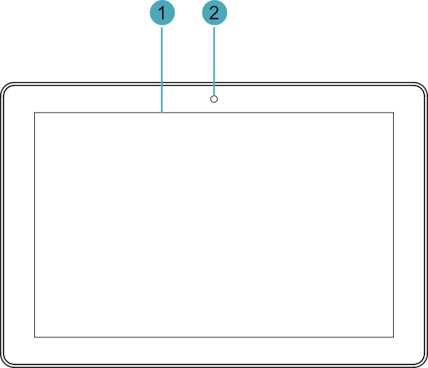
1.3.1 Front Panel
This section introduces functions and definitions of front panel.
| NO. | Function Definition |
|---|---|
| 1 | 1 x LCD display, 10.1-inch LCD touch screen, which supports up to 1028x800 resolution and multi-point capacitive touchscreen. |
| 2 | 1 x camera (optional), 8 Megapixel front camera. |
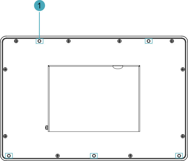
1.3.2 Rear Panel
This section introduces interfaces and definitions of rear panel.
| NO. | Function Definition |
|---|---|
| 1 | 5 x installation holes of buckle, which are used to fix the buckles to the device for installation. You only need to use 4 installation holes during installation, and reserve one as a spare. |
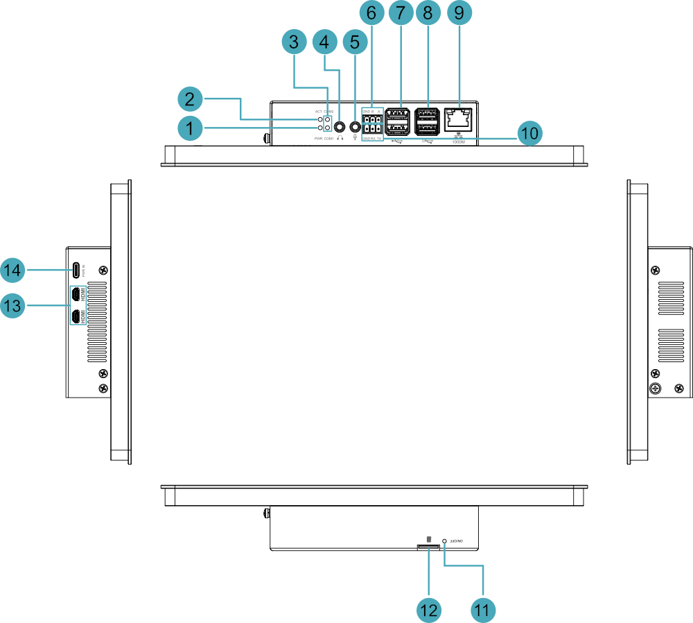
1.3.3 Side Panel
This section introduces interfaces and definitions of side panel.
| NO. | Function Definition |
|---|---|
| 1 | 1 x red power indicator, which is used to check the status of device power-on and power-off. |
| 2 | 1 x green system status indicator, which is used to check the working status of device. |
| 3 | 2 x green UART indicators, which is used to check the communication status of UART port. |
| 4 | 1 x Audio Output (HPO), 3.5mm audio jack connector(green), stereo audio output. |
| 5 | 1 x Audio Input (LINE IN), 3.5mm audio jack connector(red), supporting stereo audio input. |
| 6 | 1 x RS485 port, 3-Pin 3.5mm pitch phoenix terminal, which is used to connect the third-party control equipment. |
| 7 | 2 x USB 2.0 ports, Type-A connector, each channel supports up to 480Mbps. |
| 8 | 2 x USB 3.0 ports, Type-A connector, each channel supports up to 5Gbps. |
| 9 | 1 x 10/100/1000M adaptive ethernet port, RJ45 connector, with led indicator. It can be used to access the network. |
| 10 | 1 x RS232 port, 3-Pin 3.5mm pitch phoenix terminal, which is used to connect the third-party control equipment. |
| 11 | 1 x power button, which is used to turn on and turn off the device. |
| 12 | 1 x Micro SD card slot, which is used to install Micro SD card. It supports booting the OS from SD card. |
| 13 | 2 x HDMI ports, Micro HDMI connector, which can connect a display and supports 4K 60Hz. |
| 14 | 1 x DC input, USB Type-C connector, which supports 5V 5A power input. |
1.4 Button
The ED-HMI3020-101C includes a ON/OFF button, and the silkscreen is “ON/OFF”. If you run Raspberry Pi Desktop, you can initiate a clean shutdown by briefly pressing the power button. A menu will appear asking whether you want to shutdown, reboot, or logout:
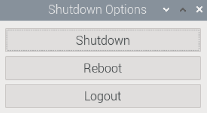
TIP:
If you run Raspberry Pi Desktop, you can press the power button twice in quick succession to shut down.
1.5 Indicator
This section introduces various statuses and meanings of indicators contained in ED-HMI3020-101C.
| Indicator | Status | Description |
|---|---|---|
| PWR | On | The device has been powered on. |
| Blink | Power supply of the device is abnormal, please stop the power supply immediately. | |
| Off | The device is not powered on. | |
| ACT | Blink | The system started successfully and is reading and writing data. |
| Off | The device is not powered on or does not read and write data. | |
| COM1~COM2 | On/Blink | Data is being transmitted. |
| Off | The device is not powered on or there is no data transmission. | |
| Yellow indicator of Ethernet port | On | The Ethernet connection is in the normal state. |
| Blink | The Ethernet connection is abnormal. | |
| Off | The Ethernet connection is not set up. | |
| Green indicator of Ethernet port | On | The Ethernet connection is in the normal state. |
| Blink | Data is being transmitted over the Ethernet port. | |
| Off | The Ethernet connection is not set up. |
TIP:
The function of the PWR/ACT indicator on the Raspberry Pi 5 has been transferred to the separate PWR and ACT indicators by default, so the PWR/ACT indicator remains on after the device is powered on.
1.6 Interface
Introducing the definition and function of each interface in the product.
1.6.1 Micro SD Card Slot
The ED-HMI3020-101C includes a Micro SD card slot, and the silkscreen is " ",which supports the installation of a Micro SD card for booting the system.
1.6.2 Power Supply
The ED-HMI3020-101C includes one power input, and the silkscreen is “PWR IN”. The connector is USB Type-C, which supports 5V 5A power input.
TIP:
In order for Raspberry Pi 5 to achieve better performance, it is recommended to use a 5V 5A power adapter.
1.6.3 1000M Ethernet
ED-HMI3020-101C includes one adaptive 10/100/1000M Ethernet port, and the silkscreen is " ". The connector is RJ45, which is used to access to network. It is recommended to use the network cable of Cat6 and above.
1.6.4 HDMI
ED-HMI3020-101C includes 2 HDMI ports, and the silkscreen is "HDMI". The connector is Micro HDMI, which can connect to HDMI displays and supports up to 4Kp60.
1.6.5 USB 2.0
ED-HMI3020-101C includes 2 USB 2.0 ports, and the silkscreen is " ". The connector is USB Type-A, which can connect to standard USB 2.0 peripherals and supports up to 480Mbps.
1.6.6 USB 3.0
ED-HMI3020-101C includes 2 USB 3.0 ports, and the silkscreen is " ". The connector is USB Type-A, which can connect to standard USB 3.0 peripherals and supports up to 5Gbps.
1.6.7 RS232
ED-HMI3020-101C contains 1 RS232 port, 3-Pin 3.5mm pitch phoenix terminals. The silkscreen is "GND/RX/TX".
Pin Definition
Terminal pins are defined as follows:
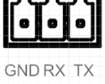 | Pin ID | Pin Name |
|---|---|---|
| 1 | GND | |
| 2 | RX | |
| 3 | TX |
The pin names of Pi5 corresponding to RS232 interface are as follows:
| Signal | Pi5 GPIO Name | Pi5 Pin Out |
|---|---|---|
| TX | GPIO4 | UART3_TXD |
| RX | GPIO5 | UART3_RXD |
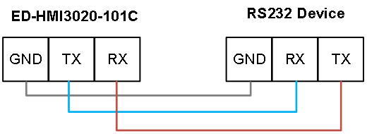
Connecting Cables
Schematic diagram of RS232 wires is as follows:
1.6.8 RS485
ED-HMI3020-101C contains 1 RS485 port, 3-Pin 3.5mm pitch phoenix terminals. The silkscreen is "A/B/GND".
Pin Definition Terminal pins are defined as follows:
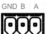 | Pin ID | Pin Name |
|---|---|---|
| 1 | GND | |
| 2 | B | |
| 3 | A |
The pin names of Pi5 corresponding to RS485 interface are as follows:
| Signal | Pi5 GPIO Name | Pi5 Pin Out |
|---|---|---|
| A | GPIO12 | UART5_TXD |
| B | GPIO13 | UART5_RXD |
Connecting Cables
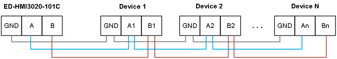
Schematic diagram of RS485 wires is as follows:
RS485 Terminal Resistor
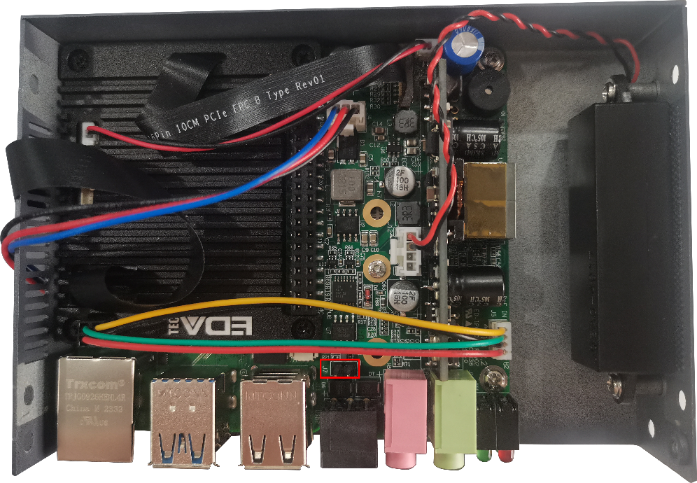
ED-HMI3020-101C contains a RS485 port. A 120R jumper resistor is reserved between A and B of RS485 line. The jumper cap can be inserted to enable the jumper resistor. By default, the jumper cap is not connected, and the 120R jumper resistor function is disabled. The position of jumper resistor in the PCBA is J7 in the figure below (red box position).
TIP:
You need to open the device case to view the position of 120R jumper resistor. For detailed operations, please refer to 2.3 Open Device Case.
1.6.9 Audio In
ED-HMI3020-101C contains one audio input (LINE IN), 3.5mm audio jack connector (red). The silkscreen is " ", supporting stereo audio input.
1.6.10 Audio Out
ED-HMI3020-101C contains one audio output (HPO), 3.5mm audio jack connector (green). The silkscreen is " ", supporting stereo audio output.
1.6.11 Speaker
The ED-HMI3020-101C contains a power amplifier output, built-in a 4Ω 3W speaker, supporting single-channel stereo output. When playing audio, if the headphone is connected to the Audio Out interface (HPO), the speaker will have no audio output.