Fails to boot ED-IPC3020/ED-HMI3020/ED-HMI3010 from SD card-Trouble Shooting
Products such as ED-IPC3020, ED-HMI3010 and ED-HMI3020 shipped prior to July 2024 may experience booting failure from the SD card after a period of use.
If you encounter such problems, refer to the following for problem identification and troubleshooting.
1 Fault Description
Describes the phenomenon of failed booting from SD card and the specific product models involved.
1.1 Fault Phenomenon
If the ED-IPC3020, ED-HMI3010 and ED-HMI3020 series products fail to boot the system from the SD card after a period of normal use, the phenomena are as follows.
After the device is normally powered on, the LCD screen of ED-HMI3010/ED-HMI3020 has no content display and a black screen appears.
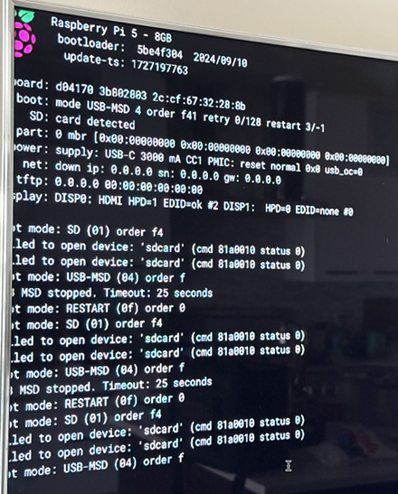
After the device is normally powered on, the LCD screen of ED-HMI3010/ED-HMI3020 displays the following figure.

After the device is normally powered on, the HDMI output of ED-IPC3020/ED-HMI3010/ED-HMI3020 is displayed the following figure.
1.2 Involved Product
The products involved in the problem of failing to boot the system from the SD card include the ED-IPC3020, ED-HMI3010-070C, ED-HMI3010-101C, ED-HMI3020-070C, and ED-HMI3020-101C.
2 Trouble Shooting
For the problem of failing to boot from SD card, it is recommended that users check whether the SD card or SD card slot is damaged, and the specific actions are described below.
2.1 Check if the SD card is damaged
TIP
We need use a pair of tweezers to pull out or insert the SD card of ED-IPC3020.
When you want pull out or insert the SD card of ED-HMI3010-070C/101C, you need open the case of ED-HMI3010-070C/101C first. For detailed operation, please refer to Open the ED-HDMI3010-070C/101C Case.
Disconnect power to the device that failed to boot from the SD card and remove the SD card.
Obtain a device that can boot normally from the SD card, insert the removed SD card into a device that can boot normally and use it to confirm if that it can boot normally from the SD card.
◆ If the device can boot from the SD card normally, the SD card is fine, skip to 2.2 Check if the SD card slot is damaged.
◆ If the device fails to boot from the SD card, it indicates a possible SD card problem and it is recommended the SD card be cleaned (wiping off oil and Thermally Conductive Silicone Crumbs from the surface of the SD card).
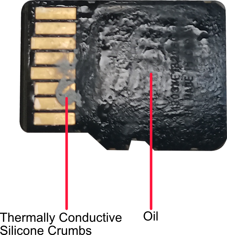
● If the device can boot from the SD card normally after cleaning the SD card, it means that the SD card is contaminated with thermally conductive silicone.
● If the device fails to boot from the SD card after cleaning the SD card, it is recommended to try replacing the SD card.
▷ If the device can boot up normally after replacing the SD card with a new one, the SD card is faulty and a new SD card is required.
▷ If the device still fails to boot after replacing it with a new SD card, skip to the 2.2 Check if the SD card slot is damaged.
2.2 Check if the SD card slot is damaged
Preparation:
- The device case has been opened, refer to Open the ED-IPC3020 Case, Open the ED-HDMI3010-070C/101C Case and Open the ED-HDMI3020-070C/101 CCase.
Steps:
Locate the SD card slot.
Remove the SD card from the card slot and use a tool to clean the SD card slot (wiping off oil and Thermally Conductive Silicone Crumbs from the SD card slot).
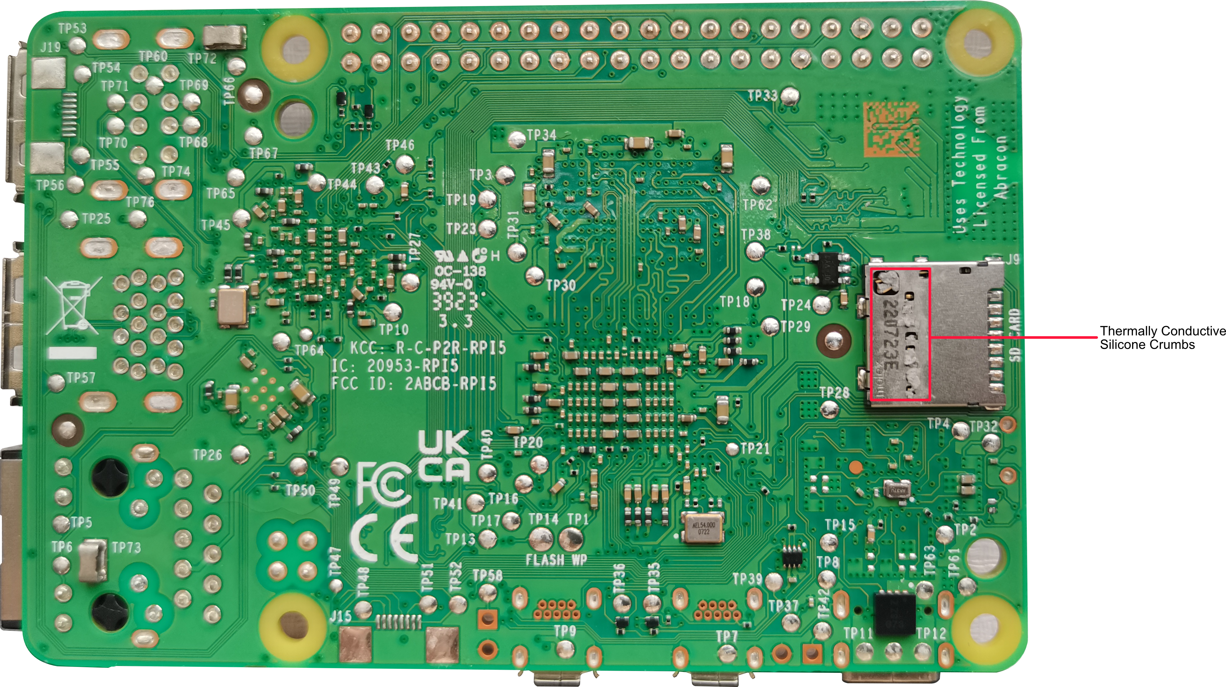
◆ If the device can boot up normally when the SD card slot is reinserted after cleaning the SD card slot, it means that the SD card slot is contaminated with thermally conductive silicone.
◆ If the device still fails to boot when the SD card slot is reinserted after cleaning the SD card slot, it means that the SD card slot may be damaged, please contact support@edatec.cn for help.
3 Open and close device case
Before inserting or removing the SD card or viewing the SD card slot, you may need to open the device case first, and after viewing it, you need to close the device case, as described below.
3.1 Open Device Case
◆ Open the ED-IPC3020 Case
Preparation:
A cross screwdriver has been prepared.
The device has been disconnected from power.
Steps:
Pull out the default configuration of phoenix connector (male for wiring).
Use a screwdriver to loosen two M3 screws on two sides counterclockwise, as shown in the red mark of figure below.

- Remove the front cover to the right, as shown in the figure below.

- Use a screwdriver to loosen four M2.5 screws and one grounding screw on two sides counterclockwise, as shown in the red mark of figure below.

- Remove the upper cover upward.

- Use a screwdriver to loosen 6 screws of PCBA mounting counterclockwise and remove the bottom cover.
◆ Open the ED-HDMI3010-070C/101C Case
Preparation:
A cross screwdriver has been prepared.
The device has been disconnected from power.
Steps:
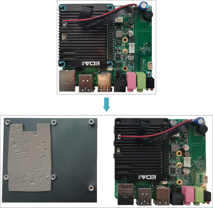
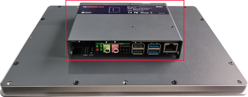
Use a screwdriver to loosen the 4 M3 screws on the ED-HMI3010-101C metal case counterclockwise, and remove the metal case, as shown in the figure below。
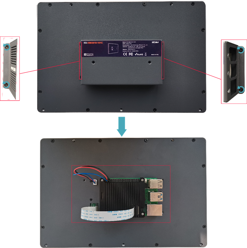
Remove the Raspberry Pi 5 by using a screwdriver to loosen counterclockwise the four M2.5 screws that secure the cooler to the Raspberry Pi 5.
◆ Open the ED-HDMI3020-070C/101 CCase
Preparation:
A cross screwdriver has been prepared.
The device has been disconnected from power.
Steps:
Pull out the default configuration of phoenix connector (male for wiring).
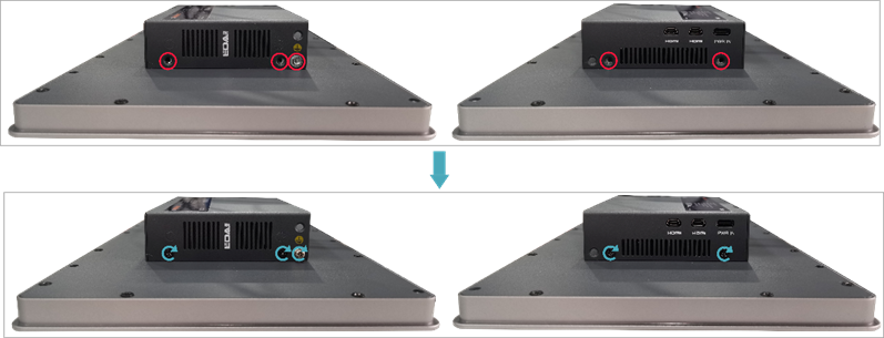
Use a screwdriver to loosen two M3 screws on two sides counterclockwise, as shown in the red mark of figure below.

Remove the front cover to the right, as shown in the figure below.

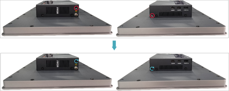
Use a screwdriver to loosen four M3 screws and one grounding screw on two sides counterclockwise, as shown in the red mark of figure below.

- Remove the metal case upward and flip it clockwise to the PCBA side.
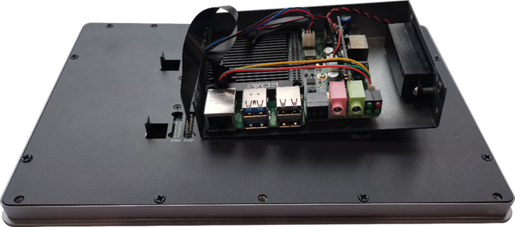
- Use a screwdriver to loosen 6 screws of PCBA mounting counterclockwise to separate the PCBA from the metal case, and flip it to the back of PCBA.
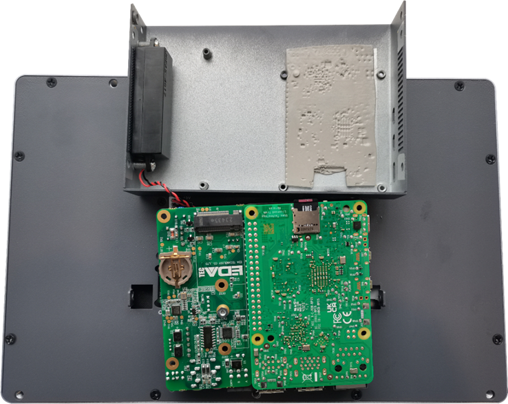
3.2 Close Device Case
◆ Close the ED-IPC3020 Case
Preparation:
A cross screwdriver has been prepared.
Steps:
- Place the PCBA on the bottom cover of ED-IPC3020, align the 6 mounting holes on the PCBA with the studs on the bottom cover, then insert 6 mounting screws, and tighten clockwise to fix the PCBA on the bottom cover.。
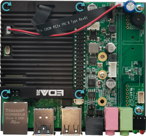
- Close the upper cover.
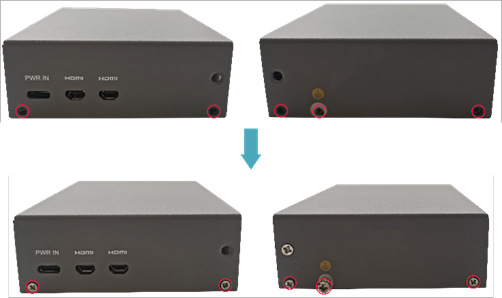
Align the screw holes on the upper and bottom cover, and use a screwdriver to tighten four M2.5 screws and one grounding screw on two sides clockwise.
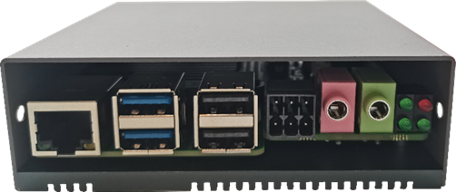
Align the interface on the PCBA with the interface holes on the front panel, insert the front cover, and then use a screwdriver to tighten the 2 M3 screws clockwise.

Plug in the default configuration of phoenix connector.
◆ Close the ED-HDMI3010-070C/101C Case
Preparation:
A cross screwdriver has been prepared.
Steps:
Place the Raspberry Pi 5 on the back of the LCD screen so that the mounting holes of the Raspberry Pi 5 can align with the four stud holes on the back of the LCD screen.
Place the cooler on the Raspberry Pi 5 (make sure the four mounting holes of the cooler are aligned with 4 mounting holes of the Raspberry Pi 5).
Insert the mounting screws of the Raspberry Pi 5 into the mounting holes of the cooler and tighten clockwise to fix the cooler and Raspberry Pi 5 on the back of the LCD screen.
Cover the case, insert 4 M3 screws, and tighten clockwise to fix the case to the back of the LCD screen.
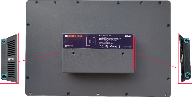
◆ Close the ED-HDMI3020-070C/101C Case
Preparation:
A cross screwdriver has been prepared.
Steps:
- Turn the PCBA over to port side, place the PCBA on the metal case to align the 6 mounting holes on the PCBA with the studs on the metal case. Then insert 6 mounting screws, and tighten clockwise to fix the PCBA to the metal case.
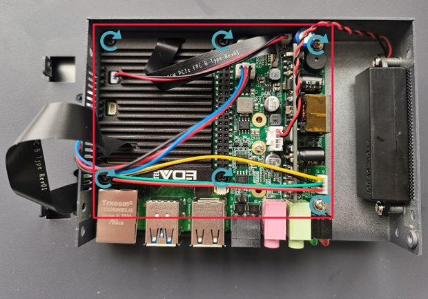
- Flip the metal case downward, align the screw mounting holes on the metal case with the screw mounting holes on the back of the LCD screen, and cover it downward on the back of the LCD screen.
- Use a screwdriver to tighten four M3 screws and one grounding screw on two sides clockwise.
- Align the ports on the PCBA with the port’s holes on the side panel, and insert the side cover.

- Use a screwdriver to tighten 2 M3 screws clockwise to fix the side cover.
- Plug in the default configuration of phoenix connector.
