1 Hardware Manual
This chapter introduces the product overview, packing list, appearance, button, indicator and interface.
1.1 Overview
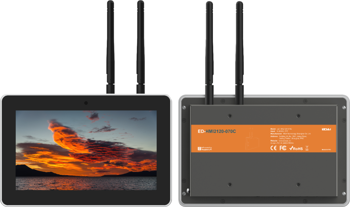
ED-HMI2120-070C is a 7-inch high reliability industrial HMI based on Raspberry Pi CM4. According to different application scenarios and user needs, different specifications of RAM and eMMC computer systems can be selected.
- Options for 1GB, 2GB, 4GB and 8GB RAM
- Options for 8GB, 16GB and 32GB eMMC storage
ED-HMI2120-070C provides common interfaces such as HDMI, USB 2.0, RS232, RS485, audio and Ethernet, and supports access to the network through Wi-Fi, Ethernet and 4G. ED-HMI2120-070C integrates supercapacitor (backup power supply, which is optional), RTC, Watch Dog, EEPROM and encryption chip, improving the ease of use and reliability of the product. It is mainly used in industrial control and IOT.
1.2 Packing List
- 1x ED-HMI2120-070C Unit
- 1 x Mounting Kit (including 4 x buckles, 4xM410 screws and 4xM416 screws)
- [optional Wi-Fi/BT version] 1x 2.4GHz/5GHz Wi-Fi/BT Antenna
- [optional 4G version] 1x 4G/LTE Antenna
1.3 Appearance
Introducing the functions and definitions of interfaces on each panel.
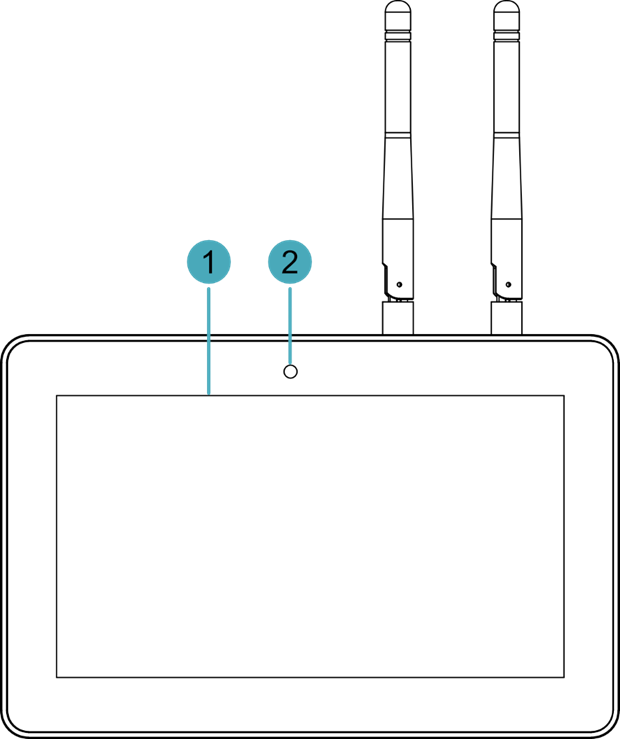
1.3.1 Front Panel
Introducing the front panel interface types and definitions.
| NO. | Function Definition |
|---|---|
| 1 | 1 x LCD display, 7-inch LCD touch screen, which supports up to 1024x600 resolution and multi-point capacitive touchscreen. |
| 2 | 1 x camera (optional), 8 Megapixel front camera. |
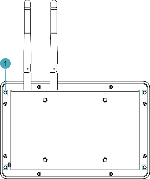
1.3.2 Rear Panel
Introducing the types and definitions of the rear panel interface.
| NO. | Function Definition |
|---|---|
| 1 | 4 x installation holes of buckle, which are used to fix the buckles to the device for installation. |
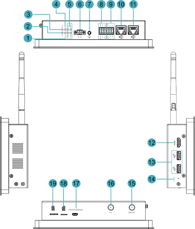
1.3.3 Side Panel
Introducing the types and definitions of side panel interfaces.
| NO. | Function Definition |
|---|---|
| 1 | 1 x green user indicator, user can customize a status according to actual application. |
| 2 | 1 x green system status indicator, which is used to check the working status of device. |
| 3 | 1 x red power indicator, which is used to check the status of device power-on and power-off. |
| 4 | 1 x green 4G indicator, which is used to check the status of 4G signal. |
| 5 | 4 x green UART indicators, using to check the communication status of UART port. |
| 6 | 1 x DC input, 2-Pin 3.5mm pitch phoenix terminals with screw holes. It supports 9V~36V input, the signal is defined as VIN+/GND. |
| 7 | 1 x Audio input/Stereo output, 3.5mm audio jack connector. It can be used as MIC IN and LINE OUT.
|
| 8 | 2 x RS232 ports, 6-Pin 3.5mm pitch phoenix terminals, which is used to connect third-party control equipment. |
| 9 | 2 x RS485 ports, 6-Pin 3.5mm pitch phoenix terminal, which is used to connect the third-party control equipment. |
| 10 | 1 x 10/100/1000M adaptive ethernet port, RJ45 connector, with led indicator.It can be used to access the network. |
| 11 | 1 x 10/100M adaptive ethernet port, RJ45 connector, with led indicator. It can be used to access the network. |
| 12 | 1 x HDMI port, type A connector, which is compatible with HDMI 2.0 standard and supports 4K 60Hz. It supports to connect a displayer. |
| 13 | 2 x USB 2.0 ports, type A connector, each channel supports up to 480Mbps transmission rate. |
| 14 | 1 x Reset button, pressing the button will reset the device. |
| 15 | 1 x Wi-Fi/BT antenna port, SMA connector, which can connect to Wi-Fi/BT antenna. |
| 16 | 1 x 4G antenna port, SMA connector, which can connect to 4G antenna. |
| 17 | 1 x Micro USB port, which supports to flash to eMMC for the system. |
| 18 | 1 x Nano SIM slot, which is used to install a SIM card for getting 4G signal. |
| 19 | 1 x Micro-SD card slot, which is used to install SD card for storing user data. |
1.4 Button
ED-HMI2120-070C includes a RESET button, which is a hidden button, and the silkscreen on the case is "RESET". Pressing the RESET button will reset the device.
1.5 Indicator
Introducing the various statuses and meanings of indicators contained in ED-HMI2120-070C.
| Indicator | Status | Description |
|---|---|---|
| PWR | On | The device has been powered on. |
| Blink | Power supply of the device is abnormal, please stop the power supply immediately. | |
| Off | The device is not powered on. | |
| ACT | Blink | The system started successfully and is reading and writing data. |
| Off | The device is not powered on or does not read and write data. | |
| USER | On | User can customize a status according to actual application. |
| Off | The device is not powered on or not defined by the user, and the default status is off. | |
| 4G | On | The dial-up is successful and the connection is normal. |
| Off | 4G signal is not connected or the device is not powered on. | |
| Yellow indicatorof Ethernet port | On | The data transmission is abnormal. |
| Blink | Data is being transmitted over the Ethernet port. | |
| Off | The Ethernet connection is not set up. | |
| Green indicatorof Ethernet port | On | The Ethernet connection is in the normal state. |
| Blink | The Ethernet connection is abnormal. | |
| Off | The Ethernet connection is not set up. | |
| COM1~COM4 | On/Blink | Data is being transmitted. |
| Off | The device is not powered on or there is no data transmission. |
1.6 Interface
Introducing the definition and function of each interface in the product.
1.6.1 Card Slot
ED-HMI2120-070C includes an SD card slot and a Nano SIM card slot.
1.6.1.1 SD Card Slot
The silkscreen on the case of Micro SD card slot is " ", which is used to install SD card for storing user data.
1.6.1.2 SIM Card Slot
The silkscreen on the case of Nano SIM card slot is " ", which is used to install SIM card for obtaining 4G signals.
1.6.2 Power Supply Interface
The ED-HMI2120-070C includes one power input, 2-Pin 3.5mm pitch phoenix terminals with screw holes. The silkscreen of port is "VIN+/GND", and the pins are defined as follows.
 | Pin ID | Pin Name |
|---|---|---|
| 1 | GND | |
| 2 | 9V~36V |
1.6.3 Audio Interface
ED-HMI2120-070C includes one audio input, the connector is a 3.5mm 4-pole headphone jack. The silkscreen of port is " ", which supports OMTP stereo headphone output and mono microphone recording.
- When the headphone is connected, the audio output is switched to the headphone.
- When the headphone is not connected, the audio output is switched to the speaker.
1.6.4 Speaker
The ED-HMI2120-070C contains a power amplifier output, built-in a 4Ω 3W speaker, supporting single-channel stereo output. When playing audio, if the headphone is connected to the Audio interface, the speaker will have no audio output.
1.6.5 RS232 Interface
ED-HMI2120-070C include 2 RS232 ports, 6-Pin 3.5mm pitch phoenix terminals. The silkscreen of single RS232 is “IGND/TX/RX”.
Pin Definition
Terminal pins are defined as follows:
 | Pin ID | Pin Name |
|---|---|---|
| 1 | GND | |
| 2 | GND | |
| 3 | RS232-1_TX | |
| 4 | RS232-3_TX | |
| 5 | RS232-1_RX | |
| 6 | RS232-3_RX |
The pin names of CM4 corresponding to RS232 interface are as follows:
| Signal | CM4 GPIO Name | CM4 Pin Out |
|---|---|---|
| RS232-1_TX | GPIO4 | UART3_TXD |
| RS232-3_TX | GPIO0 | UART2_TXD |
| RS232-1_RX | GPIO5 | UART3_RXD |
| RS232-3_RX | GPIO1 | UART2_RXD |
Connecting Cables
Schematic diagram of RS232 wires is as follows:
1.6.6 RS485
ED-HMI2120-070C include 2 RS485 ports, 6-Pin 3.5mm pitch phoenix terminals. The silkscreen of single RS485 is “IGND/A/B”.
Pin Definition
Terminal pins are defined as follows:
 | Pin ID | Pin Name |
|---|---|---|
| 1 | GND | |
| 2 | GND | |
| 3 | RS485-2_A | |
| 4 | RS485-4_A | |
| 5 | RS485-2_B | |
| 6 | RS485-4_B |
The pin names of CM4 corresponding to RS485 interface are as follows:
| Signal | CM4 GPIO Name | CM4 Pin Out |
|---|---|---|
| RS485-2_A | GPIO12 | UART5_TXD |
| RS485-4_A | GPIO8 | UART4_TXD |
| RS485-2_B | GPIO13 | UART5_RXD |
| RS485-4_B | GPIO9 | UART4_RXD |
Connecting Cables
Schematic diagram of RS485 wires is as follows:
RS485 terminal resistance configuration
ED-HMI2120-070C contain 2 RS485 ports. A 120R jumper resistor is reserved between A and B of RS485 line. The jumper cap can be inserted to enable the jumper resistor. By default, the jumper cap is not connected, and the 120R jumper resistor function is disabled. The position of jumper resistor in the PCBA are J24 and J22 in the figure below (red box position).
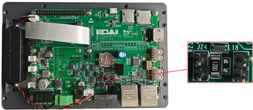
The relationship between the RS485 ports and corresponding COM ports are shown in the table below.
| Location in PCBA | Corresponding COM port | The specific location of the corresponding COM |
|---|---|---|
| J24 | COM4 |  |
| J22 | COM2 |
TIP
You need to open the device case to view the position of 120R jumper resistor. For detailed operations, please refer to 2.1.1 Open Device Case.
1.6.7 1000M Ethernet Interface
ED-HMI2120-070C includes one adaptive 10/100/1000M Ethernet port, and the silkscreen is " ". The connector is RJ45, which can support PoE with the expansion module. When accessing to network, it is recommended to use the network cable of Cat6 and above. The pins corresponding to the terminal are defined as follows:
 | Pin ID | Pin Name |
|---|---|---|
| 1 | TX1+ | |
| 2 | TX1- | |
| 3 | TX2+ | |
| 4 | TX2- | |
| 5 | TX3+ | |
| 6 | TX3- | |
| 7 | TX4+ | |
| 8 | TX4- |
1.6.8 100M Ethernet Interface
ED-HMI2120-070C includes includes an adaptive 10/100M Ethernet port, and the silkscreen is " ". The connector is RJ45, and it is recommended to use the network cable with Cat6 and above when accessing to network. The pins corresponding to the terminal are defined as follows:
| Pin ID | Pin Name |
|---|---|---|
| 1 | TX+ | |
| 2 | TX- | |
| 3 | Rx+ | |
| 4 | - | |
| 5 | - | |
| 6 | RX- | |
| 7 | - | |
| 8 | - |
1.6.9 HDMI Interface
ED-HMI2120-070C includes one HDMI port, the silkscreen is "HDMI". The connector is type A HDMI, which can connect to an HDMI display and supports up to 4Kp60.
1.6.10 USB 2.0 Interface
ED-HMI2120-070C includes 2 USB2.0 ports, the silkscreen is " ". The connector is type A USB, which can connect to standard USB 2.0 peripherals and supports up to 480Mbps transmission rate.
1.6.11 Micro USB Interface
ED-HMI2120-070C includes one Micro USB interface, the silkscreen is "PROGRAMMING" and it can be connected to a PC to flash to eMMC of the device.
1.6.12 Antenna Interface (optional)
The ED-HMI2120-070C includes 2 SMA antenna ports, the silkscreens are "4G" and "Wi-Fi/BT" and they can be connected to the 4G antenna and Wi-Fi/BT antenna.
TIP
The number of antenna interface is related to the purchasing product model. Here, we take two antenna interfaces as an example.
1.6.13 Motherboard Interface
Introducing the interfaces reserved in the ED-HMI2120-070C, which can be obtained only after the device case is opened and can be expanded according to actual needs.
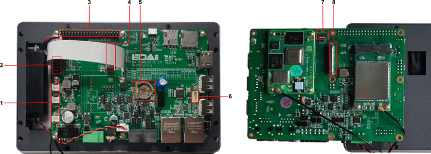
| NO. | Function |
|---|---|
| 1 | 12V 1A Power Output |
| 2 | 10-Pin GPIO Pin Header |
| 3 | 40-Pin GPIO Pin Header |
| 4 | M.2 B |
| 5 | RTC Battery Base |
| 6 | USB 2.0 Pin Header |
| 7 | CSI Interface |
| 8 | FPC HDMI Interface |
1.6.13.1 12V 1A Output
The motherboard of ED-HMI2120-070C includes 3 expanded 12V 1A power output ports with 2-Pin 2.0mm white WTB connector, which is reserved for the extended LCD screen to supply power. The pins are defined as follows:
 | Pin ID | Pin Name |
|---|---|---|
| 1 | GND | |
| 2 | 12V |
1.6.13.2 10-Pin GPIO
The motherboard of ED-HMI2120-070C includes a 10-Pin GPIO Pin Header with 2x5-Pin 2.54mm pitch, which is used to lead out the extended GPIO port. The user can customize the extension, and the pins definition are as follows:
 | Pin ID | Pin Name |
|---|---|---|
| 1 | EXIO_P10 | |
| 2 | 3V3 | |
| 3 | EXIO_P12 | |
| 4 | EXIO_P11 | |
| 5 | EXIO_P14 | |
| 6 | EXIO_P13 | |
| 7 | EXIO_P16 | |
| 8 | EXIO_P15 | |
| 9 | GND | |
| 10 | EXIO_P17 |
1.6.13.3 40-Pin GPIO
The motherboard of ED-HMI2120-070C includes a 40-Pin GPIO terminal with 2x20-Pin 2.54mm pitch, which is used to lead out the GPIO port of CM4, and reserves to connect the extended accessories. The pins are defined as follows:
 | Pin ID | Pin Name | Pin ID | Pin Name |
|---|---|---|---|---|
| 1 | 3V3_EXT | 2 | 5V2_CM4 | |
| 3 | GPIO2 | 4 | 5V2_CM4 | |
| 5 | GPIO3 | 6 | GND | |
| 7 | GPIO4 | 8 | GPIO14 | |
| 9 | GND | 10 | GPIO15 | |
| 11 | GPIO17 | 12 | GPIO18 | |
| 13 | GPIO27 | 14 | GND | |
| 15 | GPIO22 | 16 | GPIO23 | |
| 17 | 3V3_EXT | 18 | GPIO24 | |
| 19 | GPIO10 | 20 | GND | |
| 21 | GPIO9 | 22 | GPIO25 | |
| 23 | GPIO11 | 24 | GPIO8 | |
| 25 | GND | 26 | GPIO7 | |
| 27 | GPIO0 | 28 | GPIO1 | |
| 29 | GPIO5 | 30 | GND | |
| 31 | GPIO6 | 32 | GPIO12 | |
| 33 | GPIO13 | 34 | GND | |
| 35 | GPIO19 | 36 | GPIO16 | |
| 37 | GPIO26 | 38 | GPIO20 | |
| 39 | GND | 40 | GPIO21 | |
| Note:GPIO4~GPIO9、GPIO12、GPIO13 and GPIO22~GPIO27 has been used for other specific functions. If you need to use the function of its ordinary IO, you need to remove the jumper resistance on the corresponding signal line. | ||||
1.6.13.4 M.2 B Interface
The motherboard of ED-HMI2120-070C includes a M.2 B Key connector, which is used for external SSD. It is compatible with M.2 B 2230 and M.2 B 2242 SSD.
1.6.13.5 RTC Battery Base
The motherboard of ED-HMI2120-070C is integrated with RTC. For the version sold in China, we will install CR1220 battery (RTC backup power supply) by default.
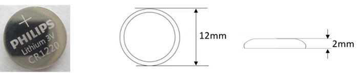
RTC can ensure that the system has an uninterrupted and reliable clock, which is not affected by factors such as the device is power down.
TIP
Some international logistics do not support the transportation of batteries, and some ex-factory devices are not equipped with CR1220 batteries. Therefore, before using RTC, please prepare a CR1220 battery and install it on the motherboard.
1.6.13.6 USB 2.0 Interface
The motherboard of ED-HMI2120-070C includes an extended USB 2.0 Pin Header with 5-Pin 1.5mm pitch WTB connector. It is used to expand a USB 2.0 interface, the pins are defined as follows:
 | Pin ID | Pin Name |
|---|---|---|
| 1 | VBUS | |
| 2 | USB_DM | |
| 3 | USB_DP | |
| 4 | GND | |
| 5 | GND |
1.6.13.7 CSI Interface
The motherboard of ED-HMI2120-070C includes one extended CSI interface, 2x15-Pin 0.4mm pitch connector and 2-Lane CSI signal. It is used to expand the connection of 8-megapixels CSI camera, the pins are defined as follows:
 | Pin ID | Pin Name | Pin ID | Pin Name |
|---|---|---|---|---|
| 1 | NC | 2 | NC | |
| 3 | 1V8_CM4 | 4 | 1V2_CSI | |
| 5 | 1V8_CM4 | 6 | GND | |
| 7 | CSI_MCLK | 8 | GND | |
| 9 | GND | 10 | 2V8_CSI | |
| 11 | NC | 12 | NC | |
| 13 | NC | 14 | NC | |
| 15 | GND | 16 | GND | |
| 17 | NC | 18 | NC | |
| 19 | GND | 20 | CSI_D1_N | |
| 21 | CSI_D1_P | 22 | GND | |
| 23 | CSI_D0_N | 24 | CSI_D0_P | |
| 25 | GND | 26 | CSI_CLK_N | |
| 27 | CSI_CLK_P | 28 | GND | |
| 29 | SCL_1V8 | 30 | SDA_1V8 |
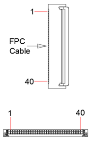
1.6.13.8 FPC HDMI Interface
The motherboard of ED-HMI2120-070C includes one extended HDMI interface with 40-pin 0.5mm pitch FPC connector. It supports video signal output to LCD screen, reserves to connect the extended LCD screen. It supports USB/I2C touch screen and backlight adjustment. The pins are defined as follows:
 | Pin ID | Pin Name | Pin ID | Pin Name |
|---|---|---|---|---|
| 1 | NC | 2 | NC | |
| 3 | NC | 4 | NC | |
| 5 | NC | 6 | NC | |
| 7 | NC | 8 | GND | |
| 9 | HDMI1_CLKN | 10 | HDMI1_CLKP | |
| 11 | GND | 12 | GND | |
| 13 | HDMI1_TX0N | 14 | HDMI1_TX0P | |
| 15 | GND | 16 | GND | |
| 17 | HDMI1_TX1N | 18 | HDMI1_TX1P | |
| 19 | GND | 20 | GND | |
| 21 | HDMI1_TX2N | 22 | HDMI1_TX2P | |
| 23 | GND | 24 | GND | |
| 25 | HDMI1_CEC | 26 | GND | |
| 27 | HDMI1_SCL | 28 | HDMI1_SDA | |
| 29 | GND | 30 | HDMI1_HPD | |
| 31 | GND | 32 | TPINT_L | |
| 33 | GND | 34 | SDA_LCD | |
| 35 | SCL_LCD | 36 | GND | |
| 37 | GND | 38 | USB_DP_LCD | |
| 39 | USB_DM_LCD | 40 | GND |
1.7 Supercapacitor (Optional)
The ED-HMI2120-070C supports an optional supercapacitor backup power module, featuring a comprehensive safe shutdown protection mechanism.
- In the event of an unexpected power failure when the supercapacitor is fully charged, the system will automatically turn off the screen backlight and reduce the CPU frequency to save power. The device continues to operate in a low-power state until the capacitor's charge is depleted, after which it automatically shuts down safely. This effectively prevents operational interruptions and data loss.
- The device provides user-customizable emergency scripts, allowing for the pre-configuration of critical data saving, backup, or other emergency procedures. At the moment of power loss, the system will automatically execute the preset scripts to ensure critical operations are completed, enabling a composed response to sudden power outages.
TIP
- For specific operations on customizing supercapacitor-related parameters, please refer to AN18 Supercapacitor Usage Guide.
- The supercapacitor requires the device to be powered on for at least 5 minutes to fully charge, and normal functionality is only guaranteed when it is fully charged.