2 Installing Device
This chapter describes the specific operations for installing the device.
2.1 Installing Raspberry Pi 4 (optional)
If the product model purchased by the customer does not include Raspberry Pi 4, Raspberry Pi 4 needs to be installed first.
Preparation:
- ED-HMI2002-070C and SD card have been obtained from the packaging box.
- Raspberry Pi 4 is ready.
- A cross screwdriver has been prepared.
Steps:
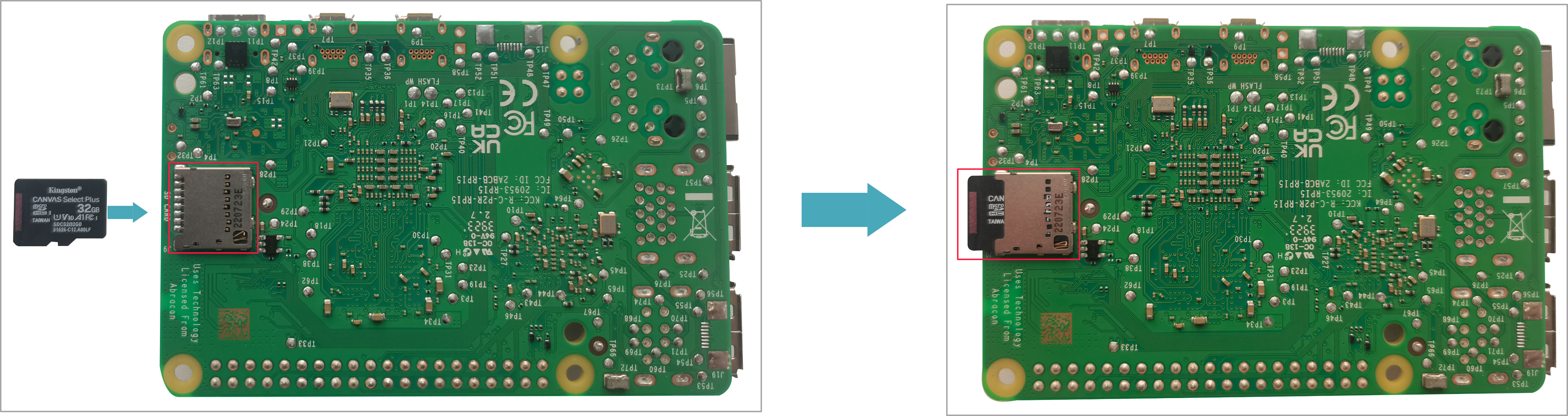
- Insert the SD card into SD card slot of Raspberry Pi 4.
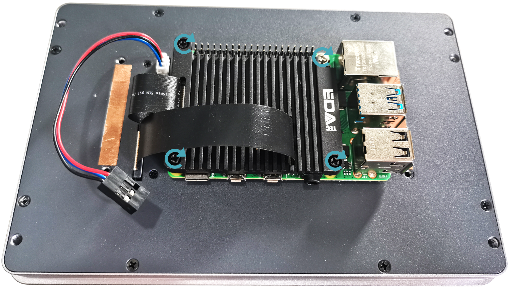
- Use a screwdriver to loosen 4 M3 screws on ED-HMI2002-070C case counterclockwise, and remove the case.
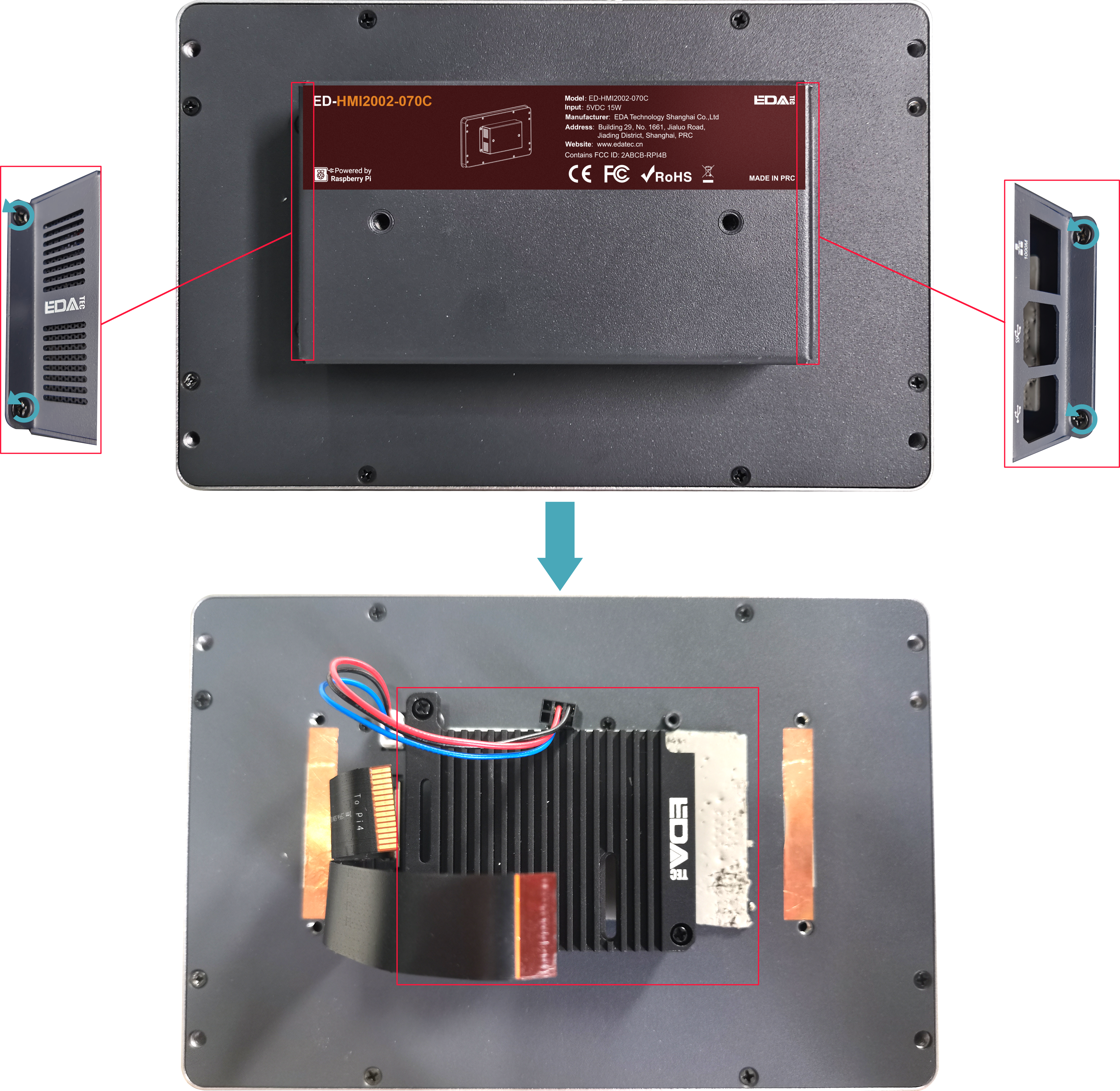
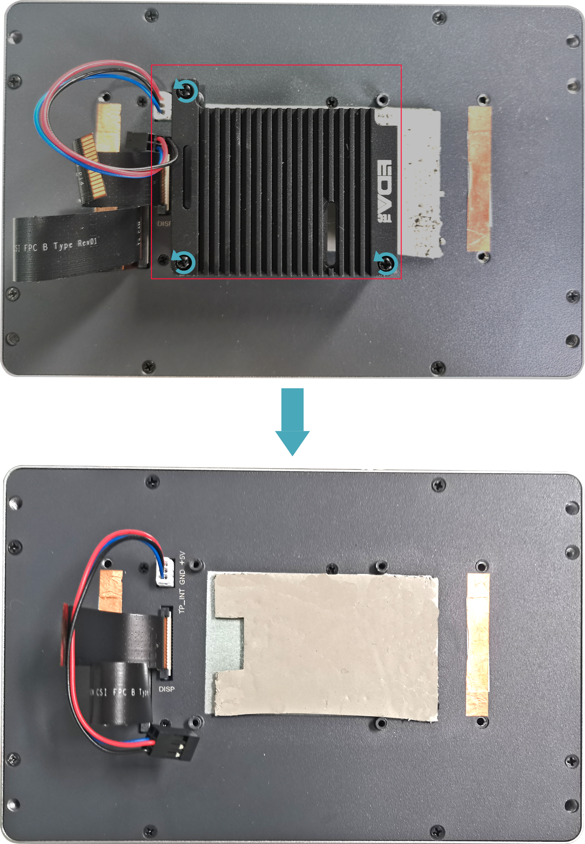
- Use a screwdriver to loosen 3 M2.5 screws on ED-Pi4PCOOLER counterclockwise, and remove the cooler.
TIP
- ED-Pi4PCOOLER is an optional cooling accessory.
- If there is a film of thermal conductive silicone, please remove it .
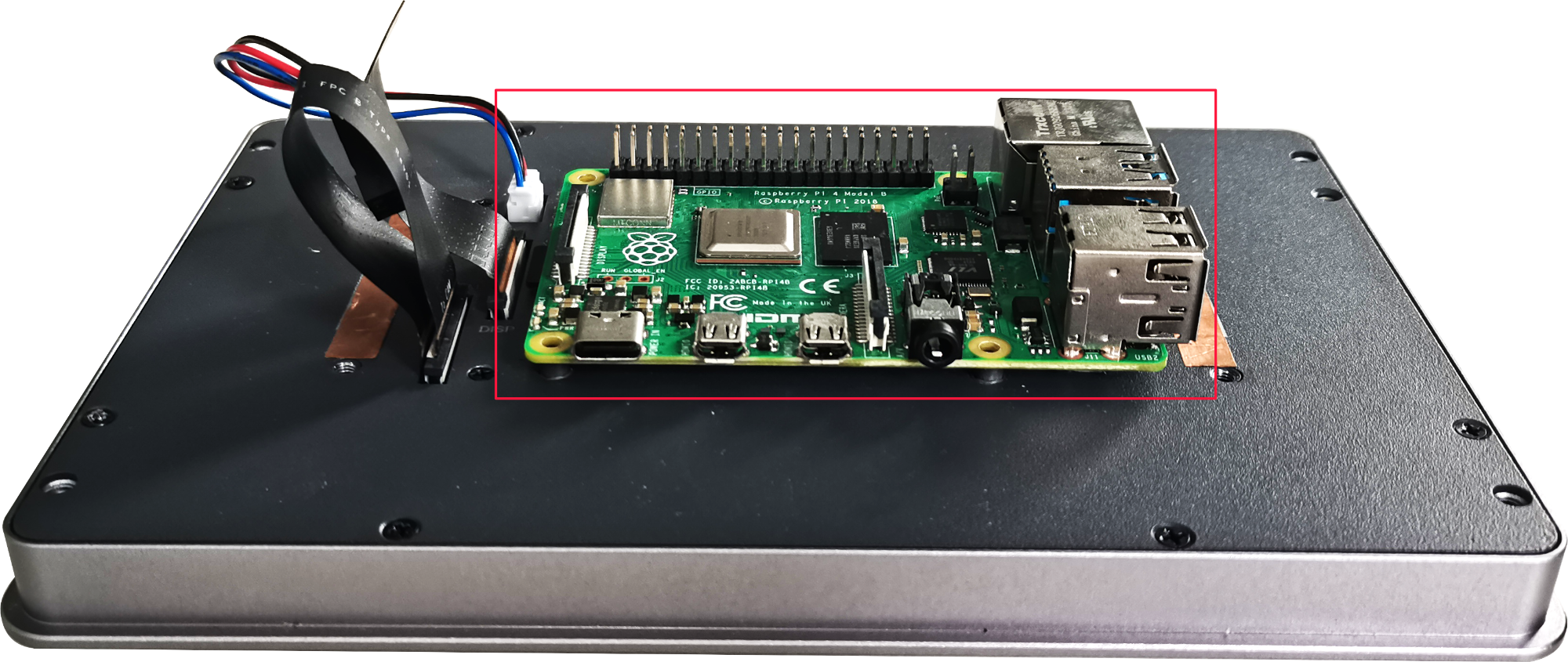
- Place the Raspberry Pi 4 on the back of the LCD screen so that the installation holes of the Raspberry Pi 4 can align with the four stud holes on the back of the LCD screen.
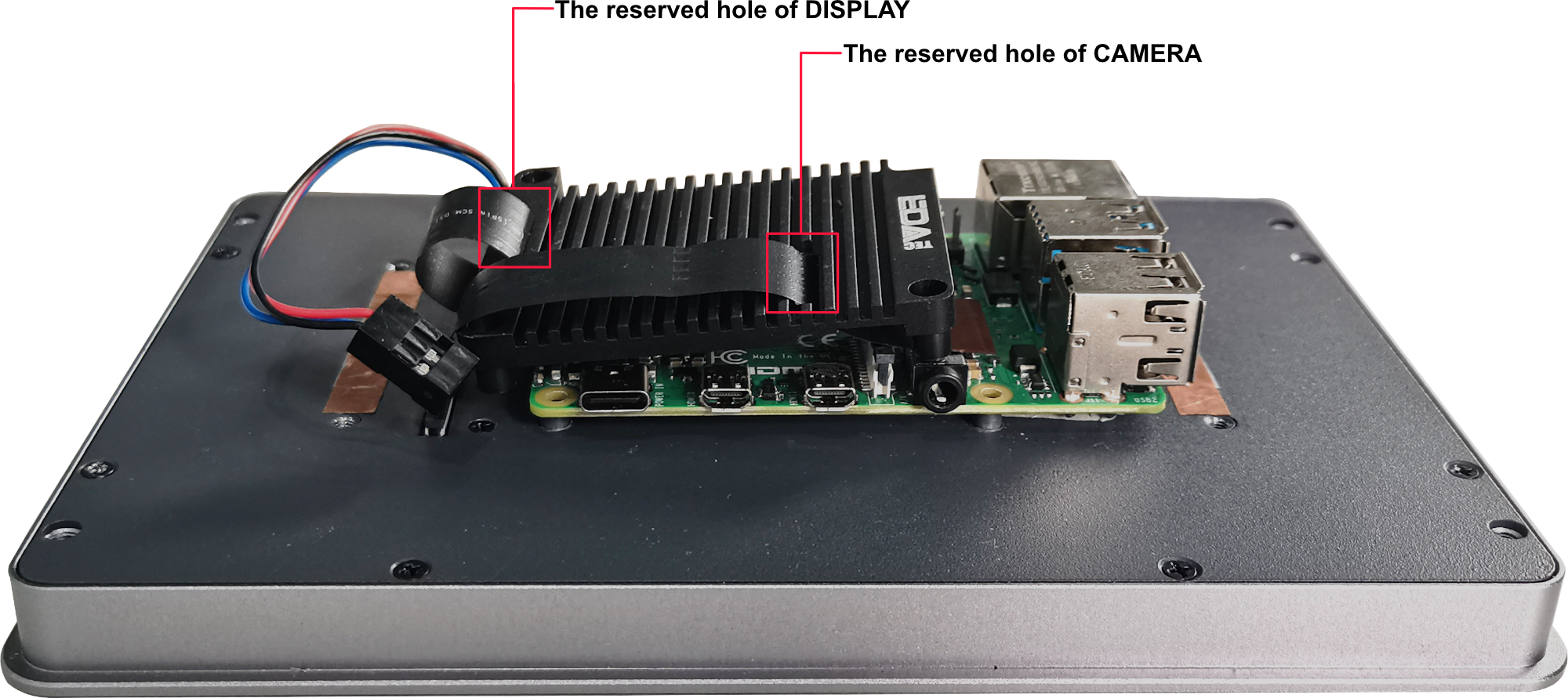
- Pass the FPC cable through the reserved hole on the ED-Pi4PCOOLER.
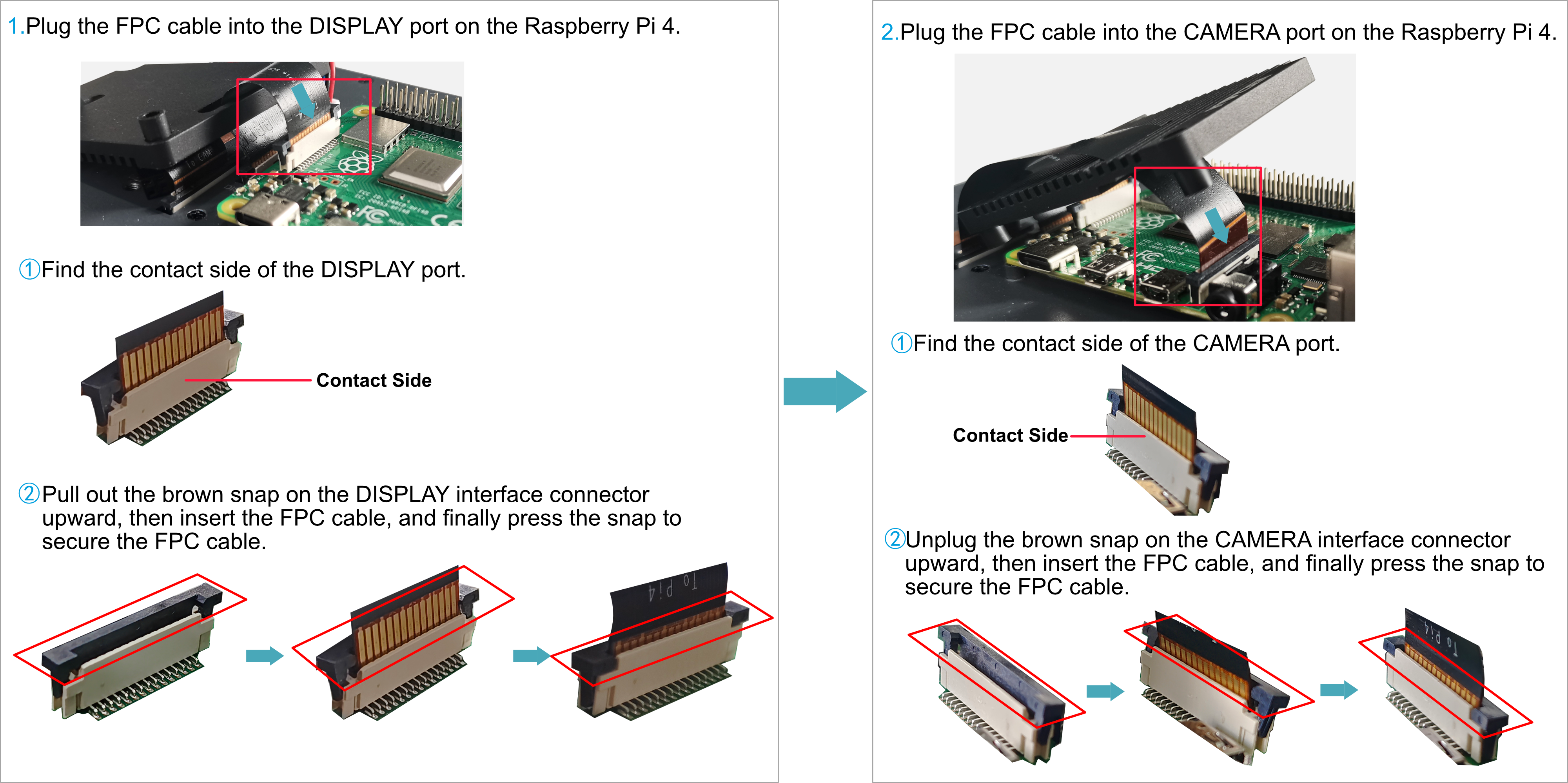
- Plug the FPC cable into the CAMERA and DISPLAY ports of the Raspberry Pi 4 respectively.
- Make 3 mounting holes of ED-Pi4PCOOLER aligning with the mounting holes of Raspberry Pi 4.
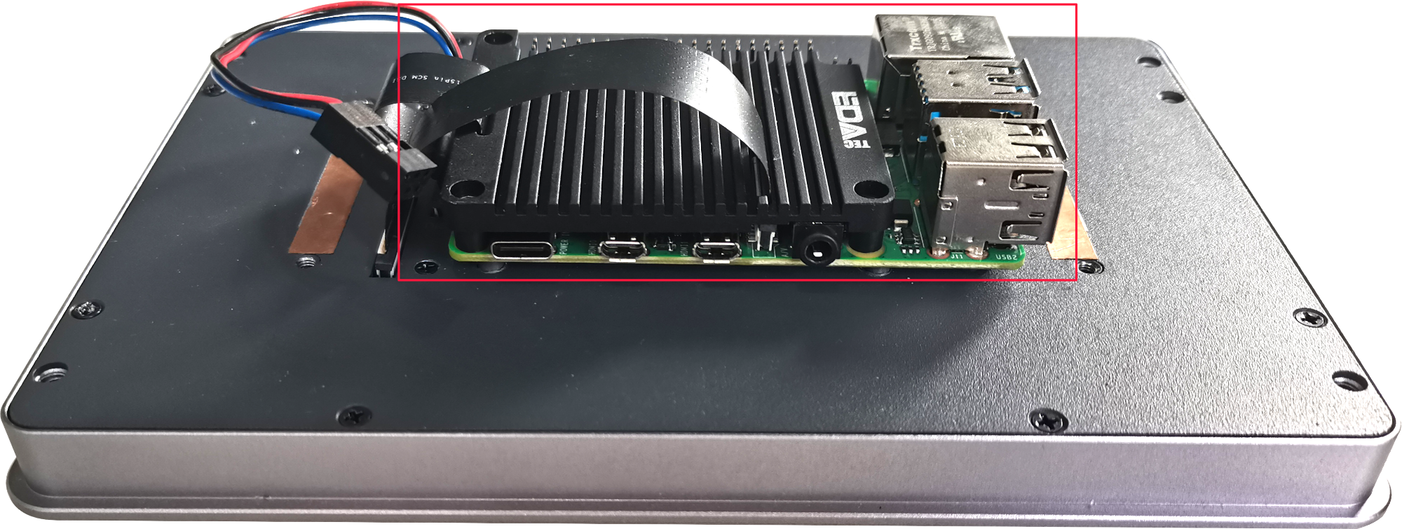
- Insert 3 M2.5*12 screws and 1 M2.5*5 screw, then tighten them clockwise to secure the Raspberry Pi 4 and ED-Pi4PCOOLER to the back side of the LCD screen.
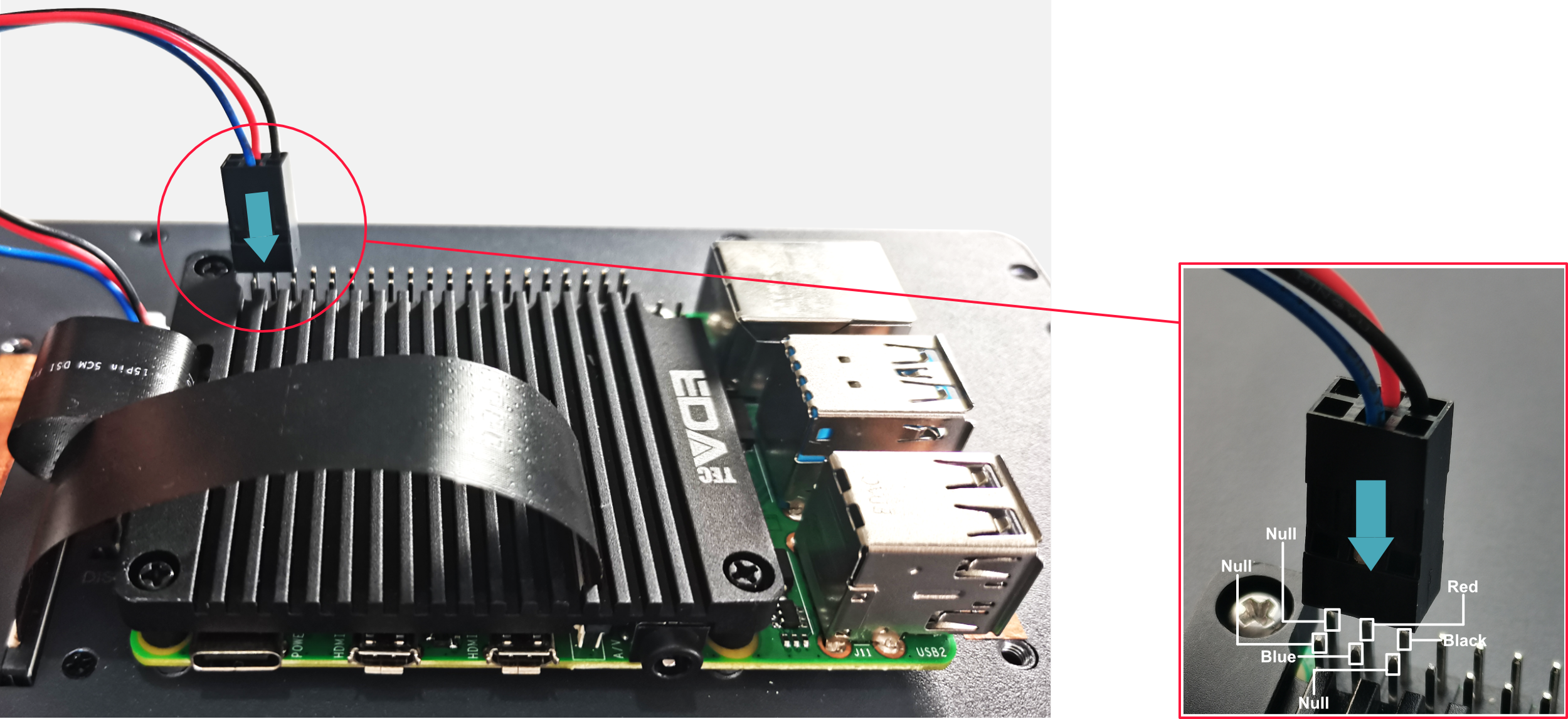
- Plug the power cord into the corresponding 40-Pin on the Raspberry Pi 4.
- Cover the case, insert 4 M3 screws, and tighten clockwise to fix the case to the back of the LCD screen.

2.2 Embedded Installation
ED-HMI2002-070C device supports embedded front installation. Standard Package doesn't include the panel mounting accessories, please purchase the ED-ACCHMI-Front from our distributors in advance.
Preparation:
ED-ACCHMI-Front accessory kit has been obtained (contains 4xbuckles, 4xM4*10 screws and 4xM4*16 screws).
A cross screwdriver has been prepared.
Steps:
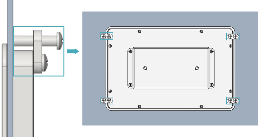
- ensure the opening size of the cabinet according to the size of ED-HMI2002-070C, as shown in the figure below.
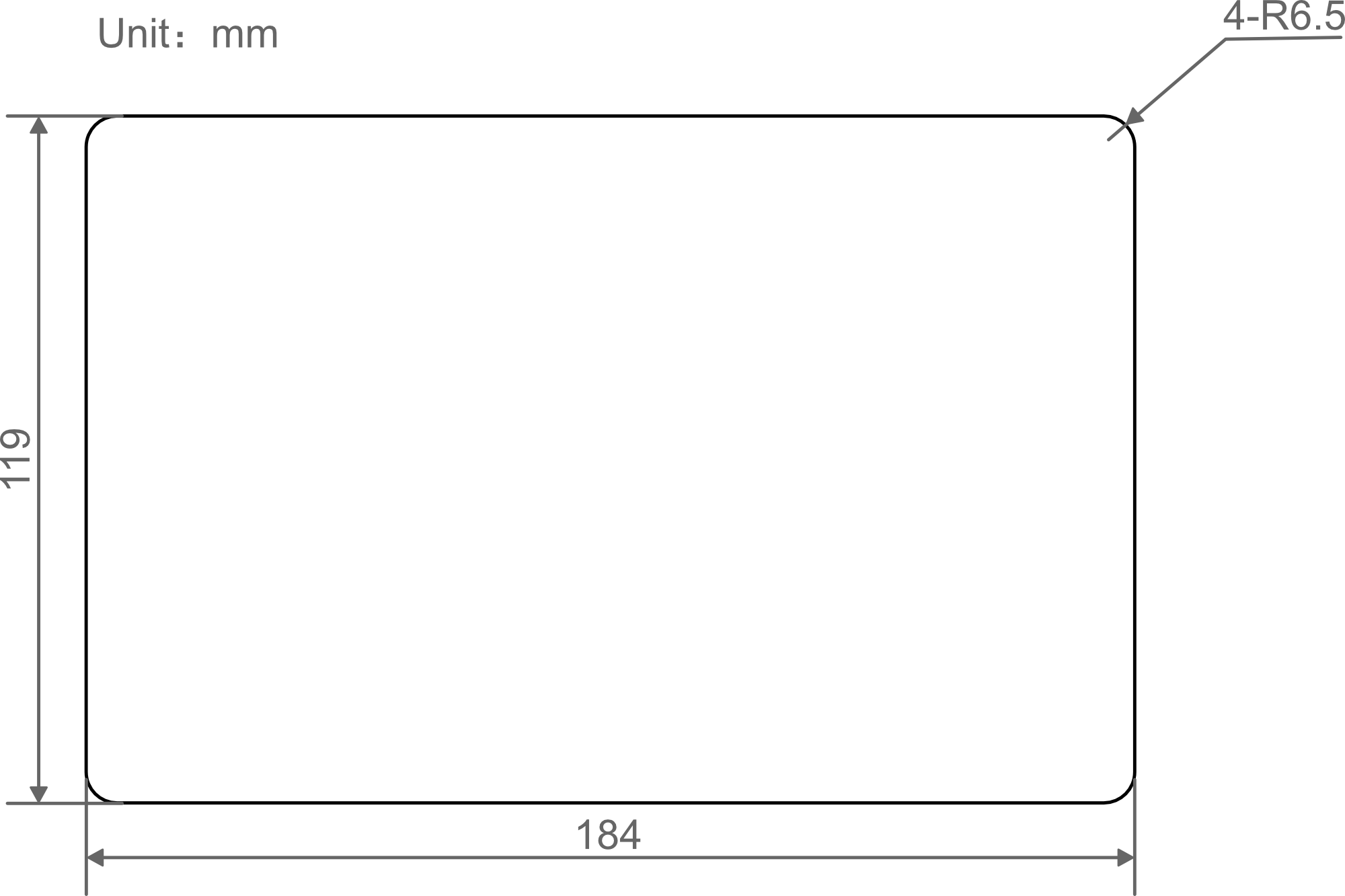
- Drill a hole on the cabinet according to the hole size of step1.
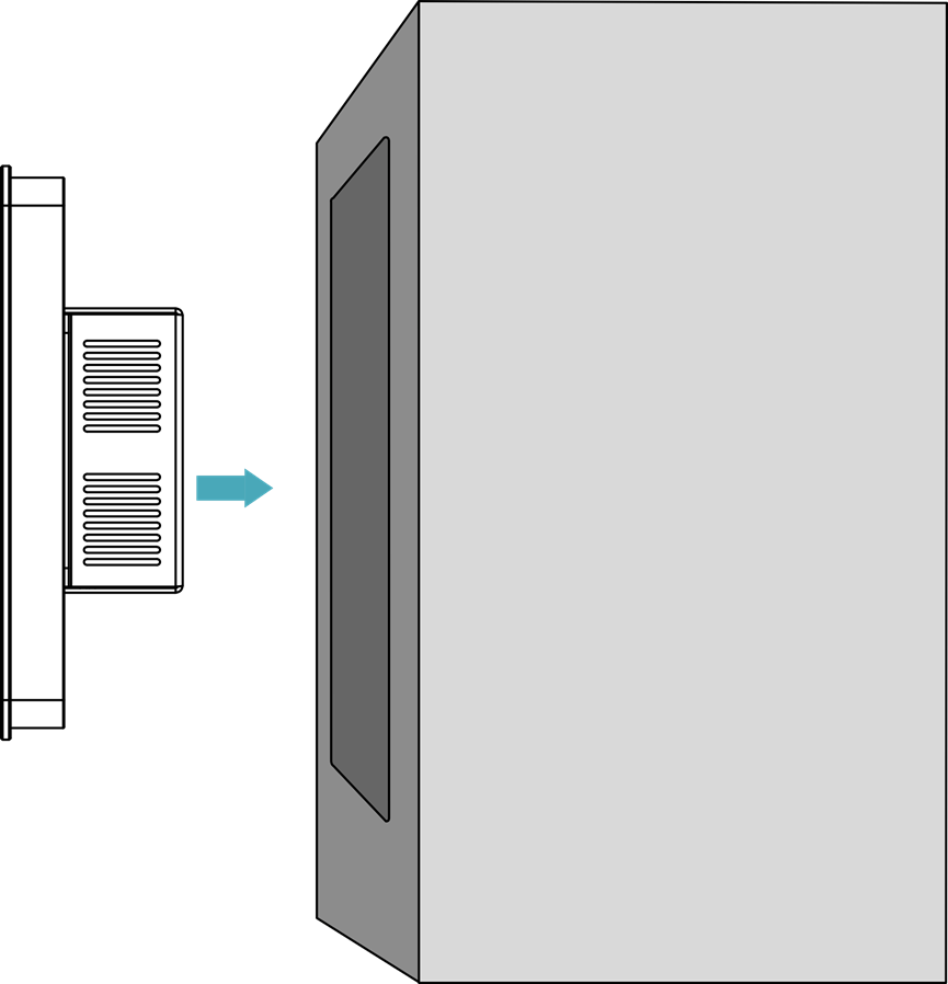
- Embed the ED-HMI2002-070C into the cabinet from the outside.
- Align the screw hole (unthreaded hole) of the buckle with the buckle installation hole on the device.
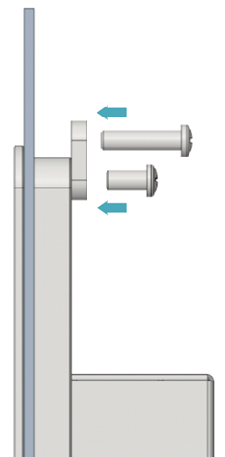
- Use 4 M4*10 screws to pass through the buckle and tighten it clockwise to fix the buckle to the device; then use 4 M4*16 screws to pass through the screw hole (threaded hole) of the buckle and tighten clockwise to the end through the buckles.