3 Software Operation Guide
3.1 Button
The D-GWL2110 includes a user-defined button located internally, connected to the CPU’s GPIO23 pin. By default, the pin is in a high-level state, which switches to a low-level state when the button is pressed.
You can use the raspi-gpio command to check the state of GPIO.
- Query the GPIO23 pin when the button is not pressed.
raspi-gpio get 23
GPIO 23: level=1 fsel=0 func=INPUT
Level of 1 indicates that the GPIO23 pin is high.
- Query the GPIO23 pin When the button is pressed.
raspi-gpio get 23
GPIO 23: level=0 fsel=0 func=INPUT
Level of 0 indicates that the GPIO23 pin is low.
3.2 LED Indicator
ED-GWL2110 includes an RGB 3-color LED indicator, and the corresponding GPIO pins are as follows:
| RGB LED PIN | GPIO |
|---|---|
| Blue | GPIO16 11 |
| Green | GPIO20 12 |
| Red | GPIO21 13 |
When the GPIO output is low, the corresponding LED is active.
You can use the raspi-gpio command to check the state of GPIO.
- Configuration parameter "op": Sets as output;
- "dl": Sets the device pin to low level;
- "dh": Sets the pin to high level.
The LED is displayed in blue.
sudo raspi-gpio set 11 op dl
sudo raspi-gpio set 12 op dh
sudo raspi-gpio set 13 op dh
The LED is displayed in green.
sudo raspi-gpio set 11 op dh
sudo raspi-gpio set 12 op dl
sudo raspi-gpio set 13 op dh
The LED is displayed in red.
sudo raspi-gpio set 11 op dh
sudo raspi-gpio set 12 op dh
sudo raspi-gpio set 13 op dl
The LED is displayed in yellow.
sudo raspi-gpio set 11 op dh
sudo raspi-gpio set 12 op dl
sudo raspi-gpio set 13 op dl
3.3 Configuring Ethernet IP
The IP address is automatically obtained by default. If you need to reconfigure the IP, you can configure it through NetworkManager.
TIP
The factory-default Lite operating system has NetworkManager enabled, allowing direct configuration via NetworkManager.
3.3.1 Raspberry Pi OS (Desktop)
In the Desktop version of the operating system, it is recommended to use the graphical NetworkManager tool to configure IP.
WARNING
The Desktop version of the operating system has the NetworkManager graphical tool installed by default.
Preparation:
Wi-Fi is enabled.
Steps:
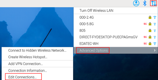
- Left-click the
 icon in the upper right corner of the desktop and select “Advanced Options→Edit Connections” in the pop-up menu.
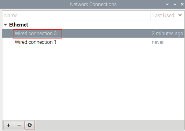
- In the pop-up "Network Connections" pane, select the connection name to be modified, and then click the Settings button below.
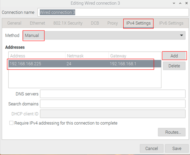
- In the pop-up "Editing Wired connection" pane, select the "IPv4 Settings" page, and then set the IP address as required.
- If you want to set the IP as a static IP, set the "Method" as "Manual", add an entry in Addresses and enter the corresponding IP address information.
- If you want to set the IP to automatic mode, you only need to set the "Method" as "Automatic(DHCP) ".
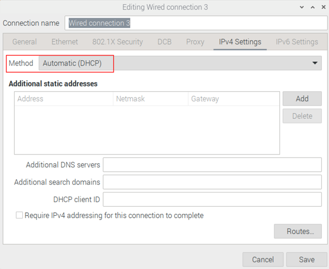
- Click "save" to return to "Network Connections" pane and close the page.
- Execute the sudo reboot command to restart the device.
3.3.2 Raspberry Pi OS (Lite)
In the Lite version of operating system, it is recommended to use the command to configure IP.
Preparation:
NetworkManager is enabled.
Steps:
Set a static IP address
- Get the assigned IP address, subnet mask and gateway address, for example, the IP address is 192.168.1.101/24 and the gateway IP is 192.168.1.1.
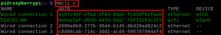
- Obtain the connection name to be modified, for example
e167c45f-efed-3f8d-89a5-f2430f92fae8. In the command pane, run the following command to query the connection name.
nmcli c
- Execute the following command to set the IP address to the obtained IP address.
sudo nmcli connection modify e167c45f-efed-3f8d-89a5-f2430f92fae8 ipv4.addresses 192.168.1.101/24 ipv4.method manual
- Execute the following command to set the gateway IP to the obtained gateway IP.
sudo nmcli connection modify e167c45f-efed-3f8d-89a5-f2430f92fae8 ipv4.gateway 192.168.1.1
Set the IP to automatic mode
- Obtain the connection name to be modified, for example e167c45f-efed-3f8d-89a5-f2430f92fae8. In the command pane, run the following command to query the connection name.
nmcli c

- Execute the following command to set the way of obtaining IP address to automatic mode.
sudo nmcli connection modify e167c45f-efed-3f8d-89a5-f2430f92fae8 ipv4.method auto
3.4 Configuring Wi-Fi (Optional)
3.5 Configuring Bluetooth (Optional)
3.6 Configuring 4G (Optional)
3.7 Configuring Storage Devices (SD Card)
3.8 Configuring RTC
3.9 GNSS
ED-GWL2110 gateway integrates L76K GPS module, which is connected with UART0 serial port of CPU. The module reports GNSS information through NMEA 0183 general protocol output statement.
3.9.1 Pin Configuration
The WakeUp signal of L76K GPS module is connected to GPIO4. If the pin module is pulled down, it will enter standby mode, and if it is pulled up or suspended, it will return to continuous mode. The Reset signal is connected to GPIO5. Pulling this pin low for 100ms will reset the module. SET signal is connected with GPIO6, which is used to configure the satellite combination. When the pin is suspended or high level, the satellite combination is GPS and Beidou, and when the pin is low level, the satellite combination is GPS and GLONASS.
The L76K GPS module’s WakeUp signal is connected to GPIO4. Pulling this pin low will put the module into standby mode, while pulling it high or leaving it floating will return it to continuous mode.
The Reset signal is connected to GPIO5. Pulling this pin low and holding it for at least 100ms will reset the module.
The SET signal is connected to GPIO6 and is used to configure the satellite combination:
- When the pin is floating or pulled high, the satellite combination is GPS + Beidou;
- When the pin is pulled low, the satellite combination is GPS + GLONASS.
| Pin | Signal | CM4 Pinout |
|---|---|---|
| 1 | GPS_WakeUp | GPIO4 |
| 2 | GPS_Reset | GPIO5 |
| 3 | GPS_Set | GPIO6 |
3.9.2 Modify config.txt to Enable Serial Port
- Execute the following command to open the
config.txtfile.
sudo nano /boot/config.txt
- Add "enable_uart=1" at the end of the file.
- Press
Ctrl+Oto save the configuration file, then pressEnter, and finally pressCtrl+X toexit the editor.
3.9.3 Check GNSS information
sudo cat /dev/ttyS0
Display GPS data as follows:
$BDGSV,3,1,11,04,29,117,20,10,,,19,16,75,160,,24,51,328,,0*4C
$BDGSV,3,2,11,25,,,27,26,,,21,34,12,198,,35,45,063,,0*76
$BDGSV,3,3,11,39,62,159,17,41,,,25,59,44,137,,0*7A
$GNRMC,053557.000,A,3027.47401,N,11424.34027,E,1.17,186.64,070223,,,A,V*05
$GNVTG,186.64,T,,M,1.17,N,2.17,K,A*2D
$GNZDA,053557.000,07,02,2023,00,00*4F
$GPTXT,01,01,01,ANTENNA OPEN*25
$GNGGA,053558.000,3027.47438,N,11424.34119,E,1,07,1.5,75.0,M,-14.1,M,,*52
$GNGLL,3027.47438,N,11424.34119,E,053558.000,A,A*4F
$GNGSA,A,3,07,08,16,31,195,,,,,,,,2.1,1.5,1.5,1*05
$GNGSA,A,3,04,39,,,,,,,,,,,2.1,1.5,1.5,4*39
$GPGSV,3,1,12,04,54,241,16,07,19,314,15,08,63,208,15,09,38,291,,0*67
$GPGSV,3,2,12,16,51,029,17,18,07,046,,21,08,175,,26,24,063,,0*6A
$GPGSV,3,3,12,27,77,065,,31,09,122,22,194,61,058,,195,46,125,21,0*66
NMEA 0183 general statement is described as follows:
- BDGSV: Visible Beidou satellite information
- GNRMC: Recommended GNSS data
- GNVTG: Relative ground heading and speed information
- GNZDA: Time and date, UTC format
- GPTXT: Text transmission
- GNGGA: Multi-satellite joint positioning data
- GNGLL: Geographical location, latitude and longitude
- GNGSA: Represents GNSS accuracy factor and effective satellite.
- GPGSV: Visible GNSS satellite
3.9.4 Use the u-center tool to view positioning information
3.9.4.1 Install serial port to network tool ser2net
sudo apt-get update
sudo apt-get install ser2net
Enable ser2net service
Ser2net configuration file is /etc/ser2net.yaml. By default, /dev/ttyS0 is configured, baud rate is 9600, and there is no check, and the corresponding TCP port is 2000.
connection: &con0096
    accepter: tcp,2000
    enable: on
    options:
      banner: *banner
      kickolduser: true
      telnet-brk-on-sync: true
    connector: serialdev,
              /dev/ttyS0,
              9600n81,local
3.9.4.2 Check ser2net Port Forwarding Service
Execute the following command to query whether ser2net has started 2000 port forwarding.
sudo netstat -ltnp | grep 2000
- If the port forwarding has been started, the following message will be displayed.
tcp6 0 0 :::2000 :::* LISTEN 720/ser2net
- If not, restart the ser2net service.
sudo systemctl restart ser2net
Positioning Configuration
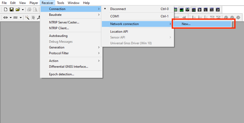
Download and install the u-center tool. If you are prompted that the
MSVCR120.dllfile is missing, please install vcredist_x86.exe.Open
u-center,Choose "Receiver"→"Port"→"Network connection"→"New…".
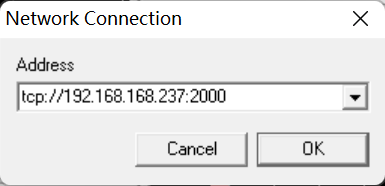
- Enter your device IP and port number 2000.
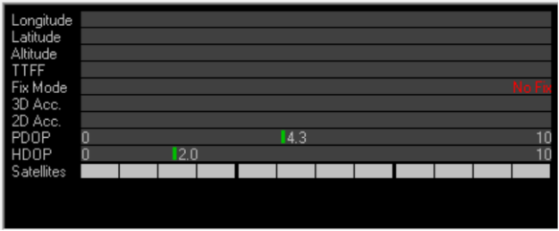
- You will see the GPS positioning information immediately after the configuration is completed.
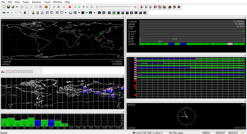
- If the Fix Mode is displayed as No Fix, it means that the positioning failed, which is usually caused by the antenna being indoors. Please put the module or antenna outdoors for testing.
NOTE
For the first time, it takes about 30 seconds to locate the module successfully when there is no large building outside. If the weather conditions are bad, it may take longer or it may not be possible to locate it.
3.10 LoRaWAN
The ED-GWL2110 supports LoRaWAN and the open-source service platform ChirpStack. The following section details the specific installation and configuration procedures.
TIP
Only the US915 LoRa gateway module is used as an example for this introduction.
3.10.1 Chirpstack Client
- The device comes pre-installed with firmware packages, LoRa module packages, and ChirpStack software packages. Verify using:
dpkg -l | grep ed-
- For OS reinstallation, refer to the OS Installation section.
3.10.2 Configuration File Modifications
3.10.2.1 Modify JSON Configuration File
- Start
ed-lora.service:
sudo systemctl enable --now ed-lora.service
- Get the configuration file path:
systemctl status ed-lora.service
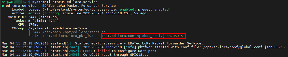
- Open the configuration file:
sudo nano /opt/ed-lora/conf/global_conf.json.US915
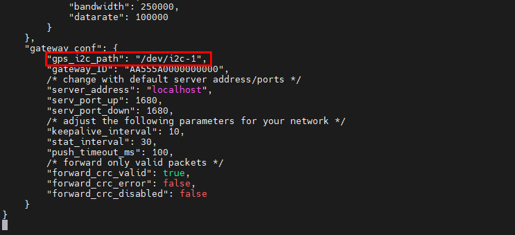
- Delete
"gps_i2c_path": "/dev/i2c-1"at the bottom.
3.10.2.2 Modify ChirpStack Configuration
- Open the configuration file.
sudo nano /etc/chirpstack-gateway-bridge/chirpstack-gateway-bridge.toml
Make the following changes:
udp_bind = "0.0.0.0:1700"→udp_bind = "0.0.0.0:1680"- Add gateway model prefix:
event_topic_template="gateway/{{ .GatewayID }}/event/{{ .EventType }}"→event_topic_template="us915_0/gateway/{{ .GatewayID }}/event/{{ .EventType }}".command_topic_template="gateway/{{ .GatewayID }}/command/#"→command_topic_template="us915_0/gateway/{{ .GatewayID }}/command/#".
TIP
For EU868/CN470 modules, replace
us915_0witheu868_0orcn470_10.Restart services:
sudo systemctl daemon-reload
sudo systemctl restart chirpstack-gateway-bridge.service ed-lora.service
3.10.3 ChirpStack Server Deployment
The ChirpStack server can be deployed either on the current device or on another device within the same LAN. This documentation uses deployment on the current device as an example. (If deploying on another LAN device, modify the udp_bind value from 0.0.0.0 to that device's IP address in Section 3.10.2.2 Modify ChirpStack Configuration).
- Install dependencies:
sudo apt install docker-compose -y
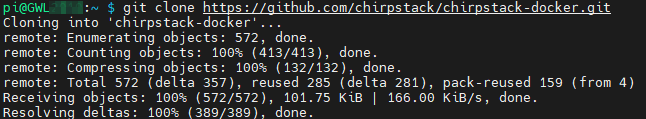
- Clone the repository:
git clone https://github.com/chirpstack/chirpstack-docker.git
- Modify configuration:
cd chirpstack-docker
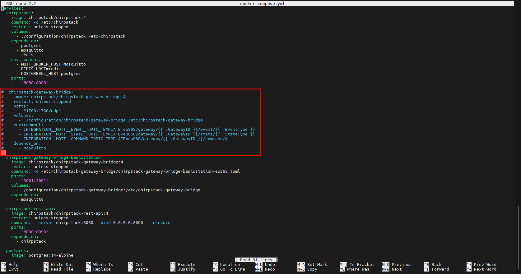
nano docker-compose.yml
- Comment out the
chirpstack-gateway-bridgesection.
services:
  chirpstack:
    image: chirpstack/chirpstack:4
    command: -c /etc/chirpstack
    restart: unless-stopped
    volumes:
      - ./configuration/chirpstack:/etc/chirpstack
    depends_on:
      - postgres
      - mosquitto
      - redis
    environment:
      - MQTT_BROKER_HOST=mosquitto
      - REDIS_HOST=redis
      - POSTGRESQL_HOST=postgres
    ports:
      - "8080:8080"

#  chirpstack-gateway-bridge:
#    image: chirpstack/chirpstack-gateway-bridge:4
#    restart: unless-stopped
#    ports:
#      - "1700:1700/udp"
#    volumes:
#      - ./configuration/chirpstack-gateway-bridge:/etc/chirpstack-gateway-bridge
#    environment:
#      - INTEGRATION__MQTT__EVENT_TOPIC_TEMPLATE=eu868/gateway/{{ .GatewayID }}/event/{{ .EventType }}
#      - INTEGRATION__MQTT__STATE_TOPIC_TEMPLATE=eu868/gateway/{{ .GatewayID }}/state/{{ .StateType }}
#      - INTEGRATION__MQTT__COMMAND_TOPIC_TEMPLATE=eu868/gateway/{{ .GatewayID }}/command/#
#    depends_on:
#      - mosquitto

  chirpstack-gateway-bridge-basicstation:
    image: chirpstack/chirpstack-gateway-bridge:4
    restart: unless-stopped
    command: -c /etc/chirpstack-gateway-bridge/chirpstack-gateway-bridge-basicstation-eu868.toml
    ports:
      - "3001:3001"
    volumes:
      - ./configuration/chirpstack-gateway-bridge:/etc/chirpstack-gateway-bridge
    depends_on:
      - mosquitto

  chirpstack-rest-api:
    image: chirpstack/chirpstack-rest-api:4
    restart: unless-stopped
    command: --server chirpstack:8080 --bind 0.0.0.0:8090 --insecure
    ports:
      - "8090:8090"
    depends_on:
      - chirpstack

  postgres:
    image: postgres:14-alpine
    restart: unless-stopped
    volumes:
      - ./configuration/postgresql/initdb:/docker-entrypoint-initdb.d
      - postgresqldata:/var/lib/postgresql/data
    environment:
      - POSTGRES_USER=chirpstack
      - POSTGRES_PASSWORD=chirpstack
      - POSTGRES_DB=chirpstack

  redis:
    image: redis:7-alpine
    restart: unless-stopped
    command: redis-server --save 300 1 --save 60 100 --appendonly no
    volumes:
      - redisdata:/data

  mosquitto:
    image: eclipse-mosquitto:2
    restart: unless-stopped
    ports:
      - "1883:1883"
    volumes:
      - ./configuration/mosquitto/config/:/mosquitto/config/

volumes:
  postgresqldata:
  redisdata:
TIP
Customize MQTT service settings in the mosquitto section.
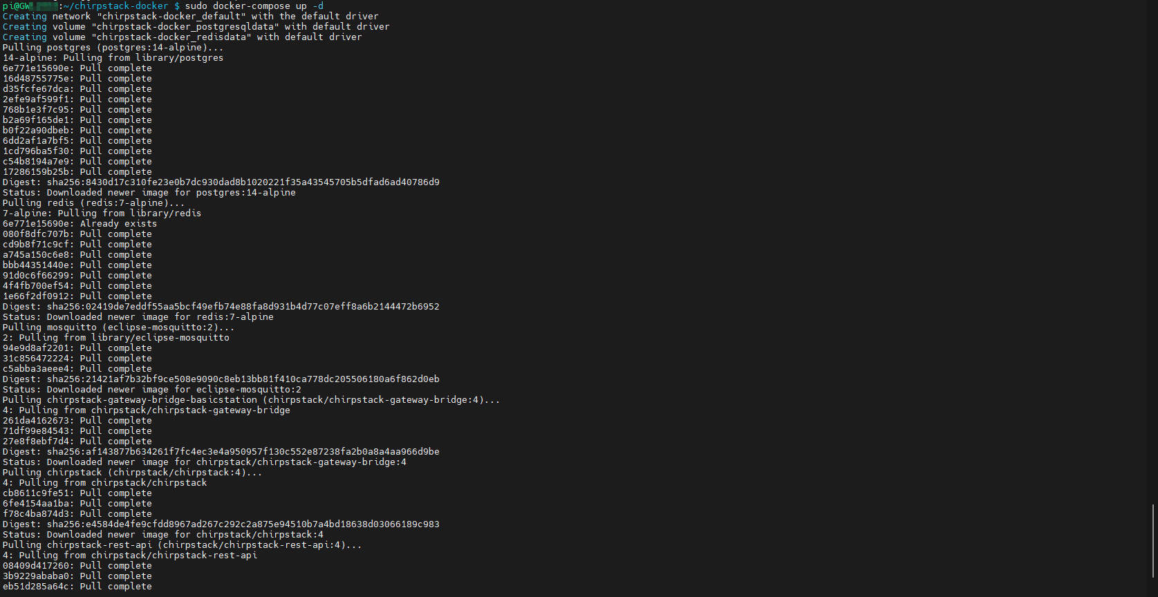
3.10.4 Start ChirpStack Server
Execute the following command on the device where the ChirpStack server is deployed to start the ChirpStack server.
sudo docker-compose up -d
3.10.5 ChirpStack Web Interface Operations
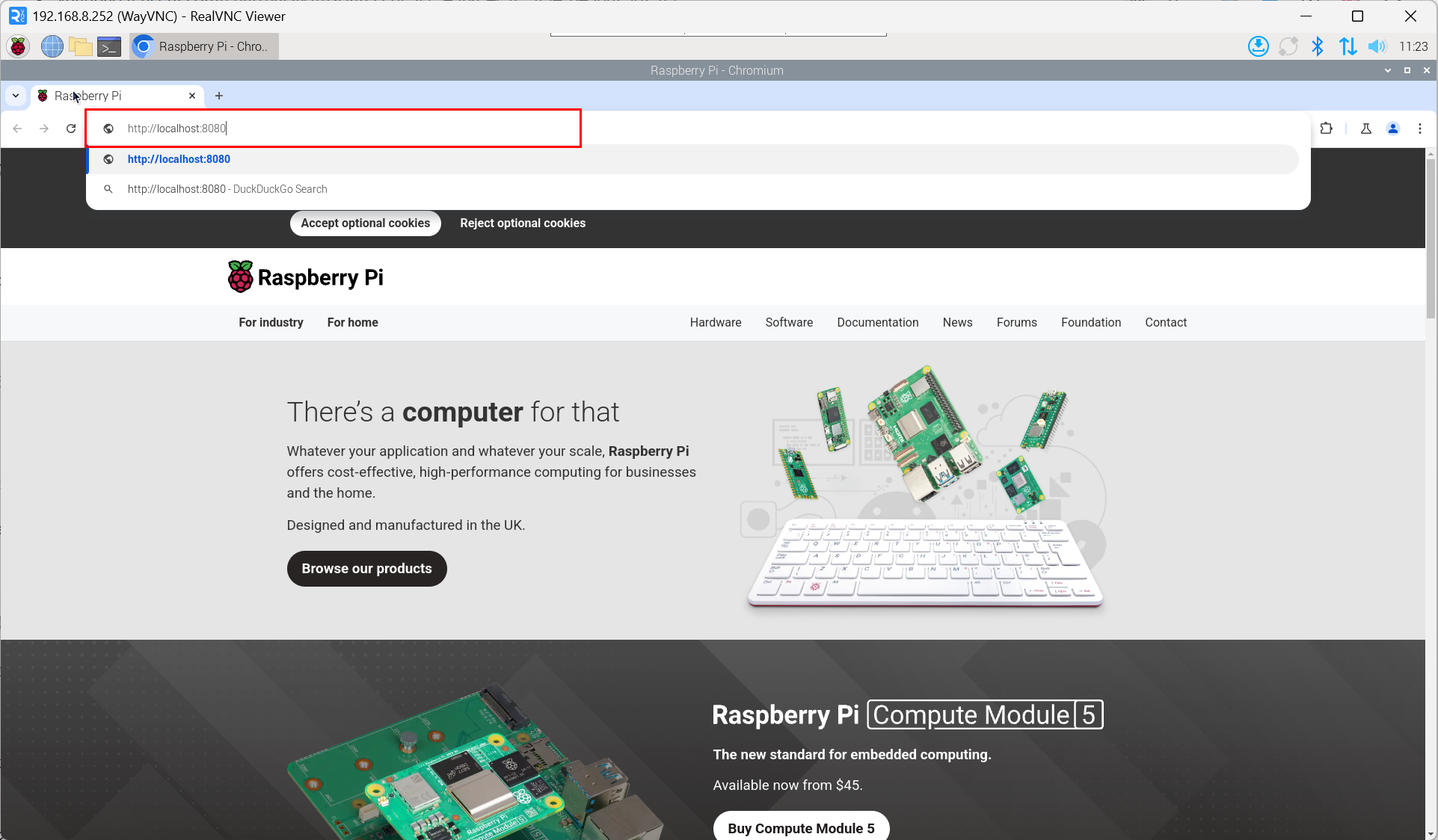
3.10.5.1 Access Web Interface
- Access via browser:
http://<server_ip>:8080.
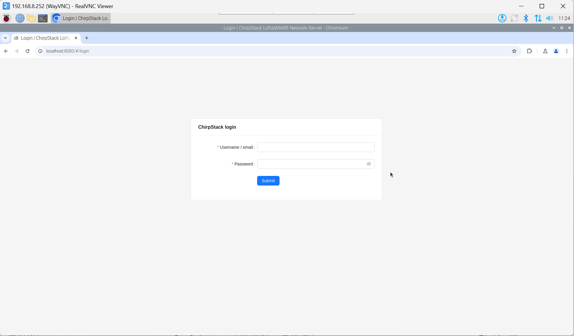
- Enter the username and password on the login interface.
TIP
The default username is admin, and the default password is admin.
3.10.5.2 Obtain Gateway ID
- Check service status:
systemctl status ed-lora.service
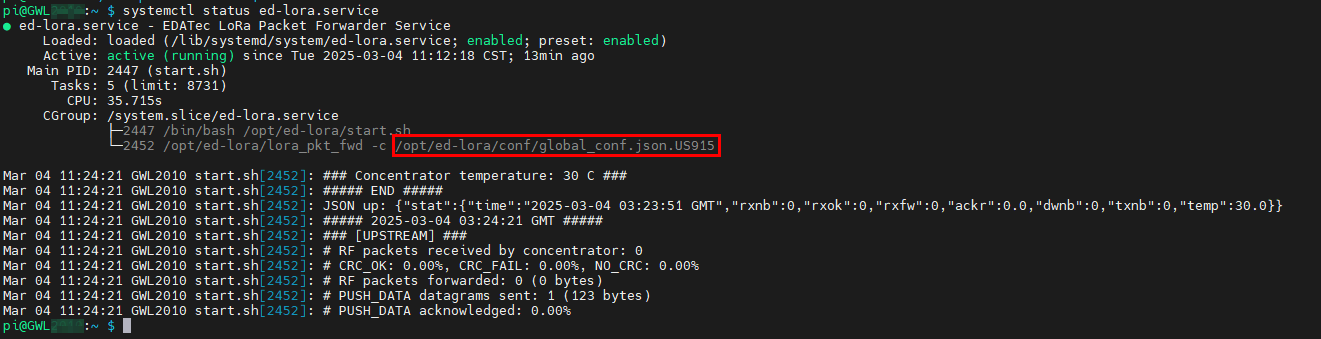
- Extract Gateway ID:
cat /opt/ed-lora/conf/global_conf.json.US915 | grep gateway

TIP
When adding a LoRa gateway on the ChirpStack server side, you need to provide the corresponding Gateway ID.
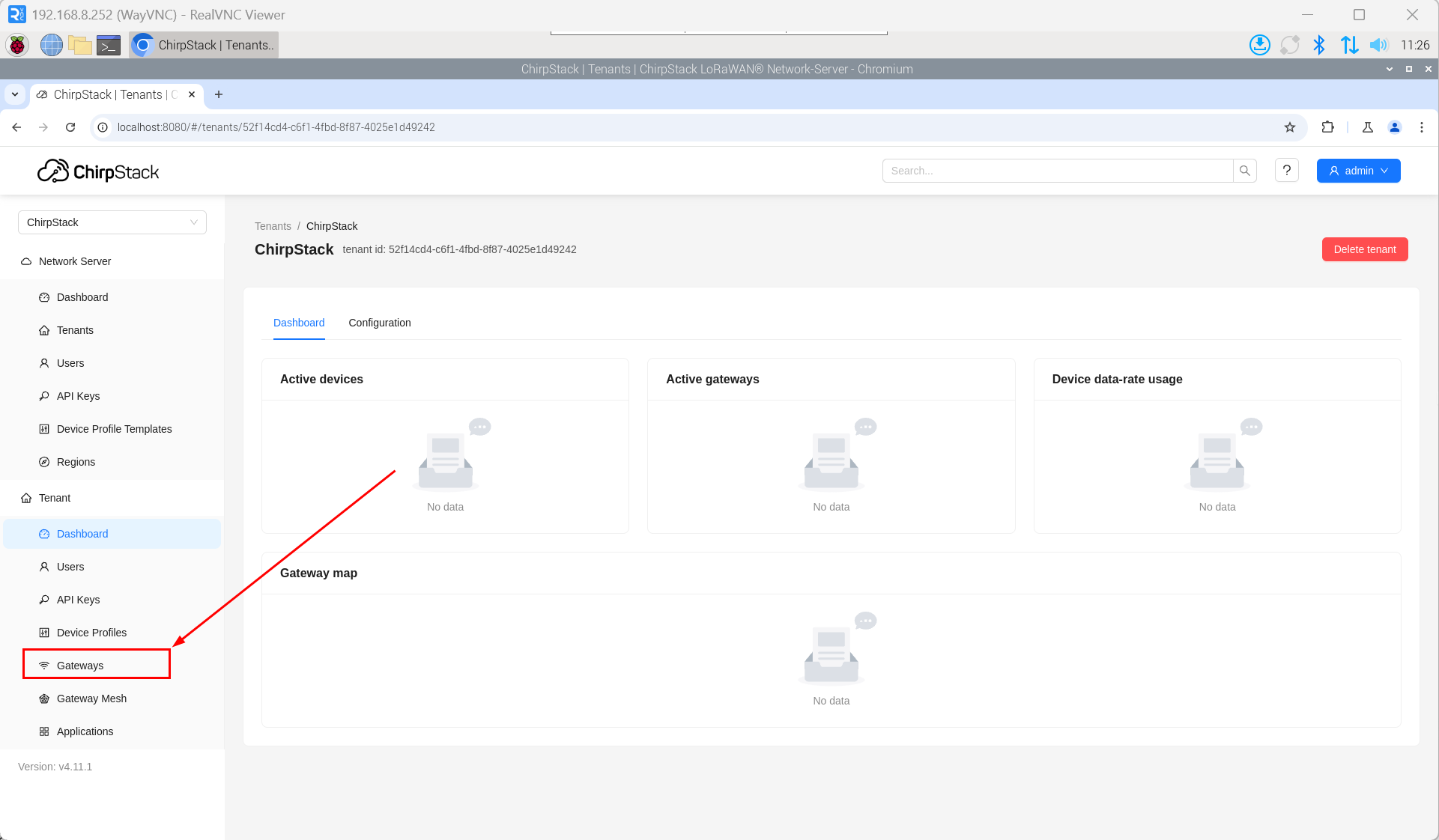
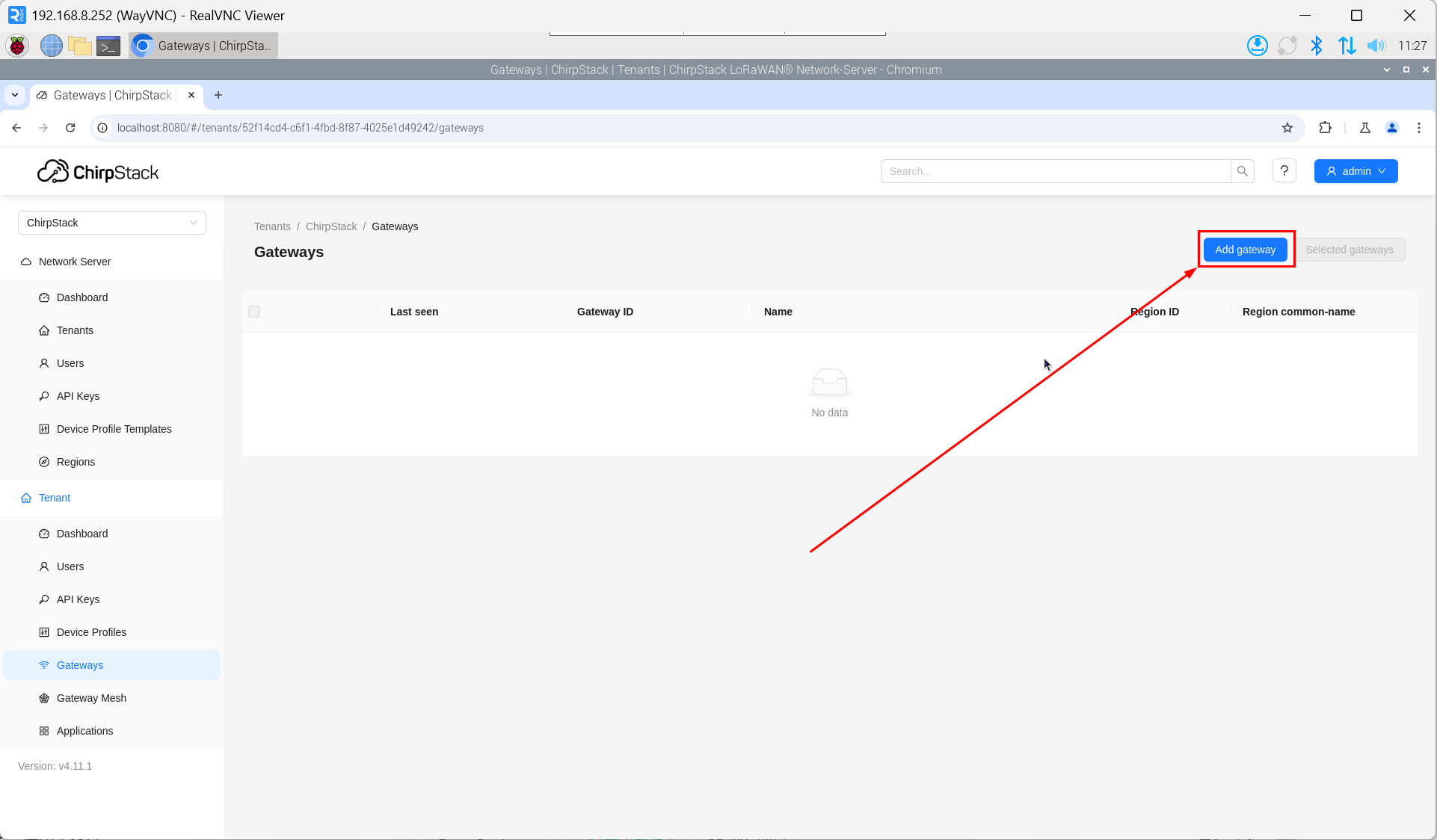
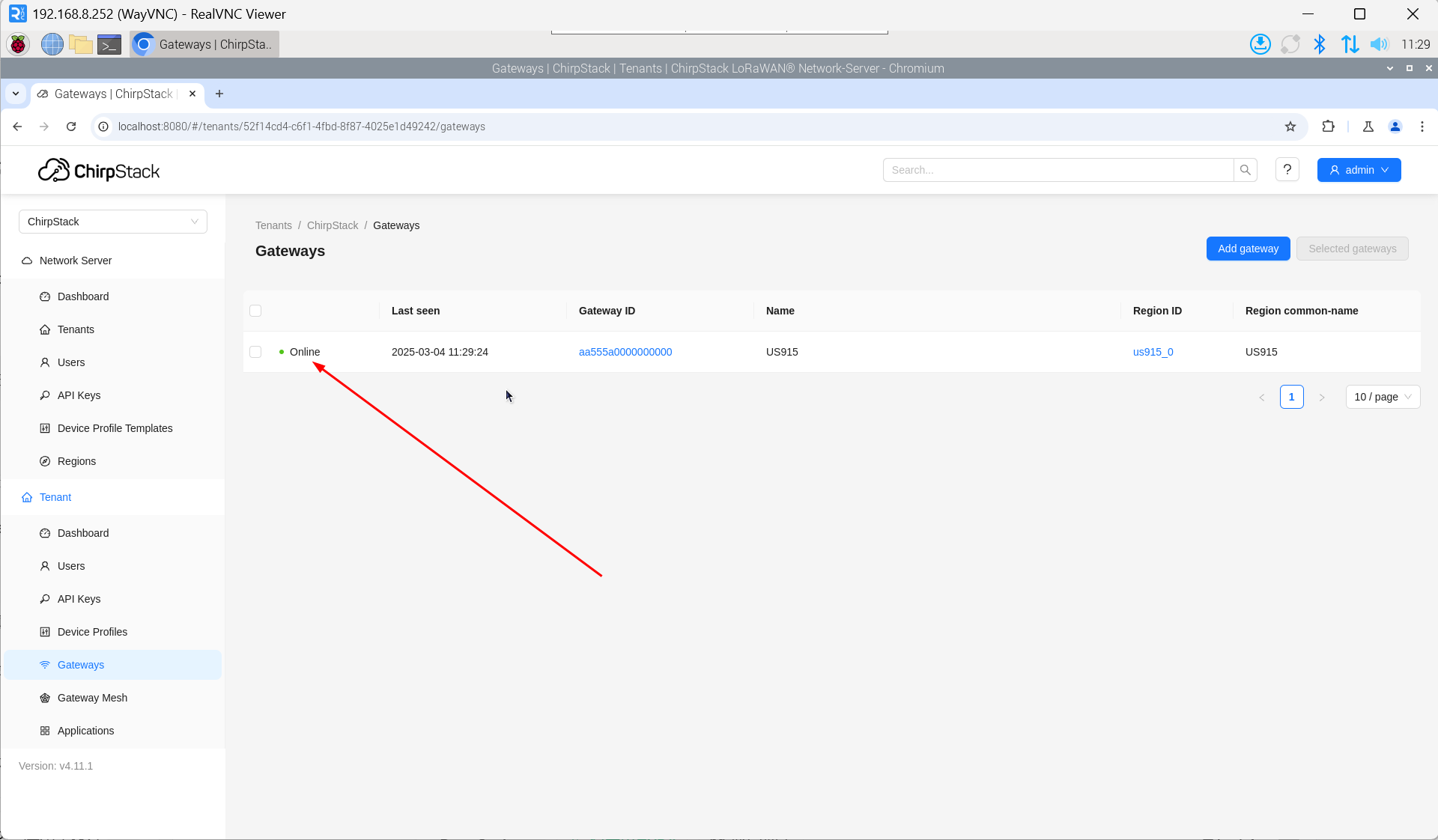
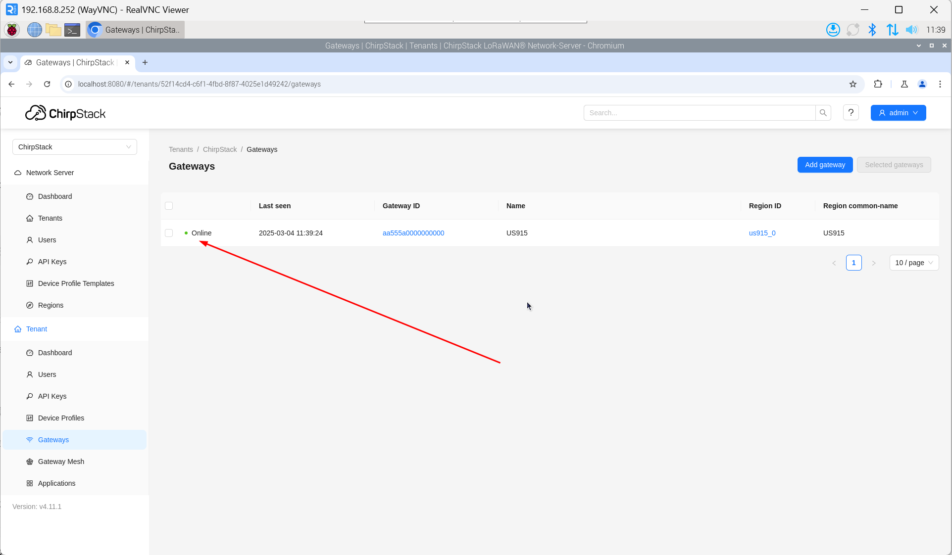
3.10.5.3 Add LoRa Gateway
- Open the ChirpStack management interface in a PC browser, then click "Gateway" → "Add gateway".
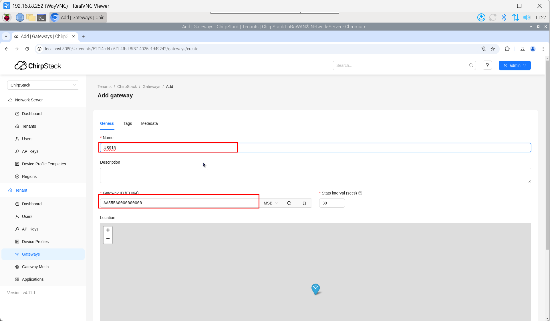
- Click "add".
- Enter the corresponding Gateway ID for your device, set the Name, then click "Submit". If the network connection is properly configured, the added gateway will transition to an Online status momentarily.
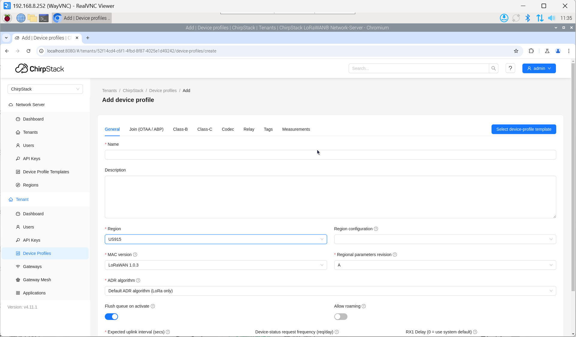
3.10.5.4 Add Device Profile
Click "Device Profile" → "Add device profile" to supplement device information.
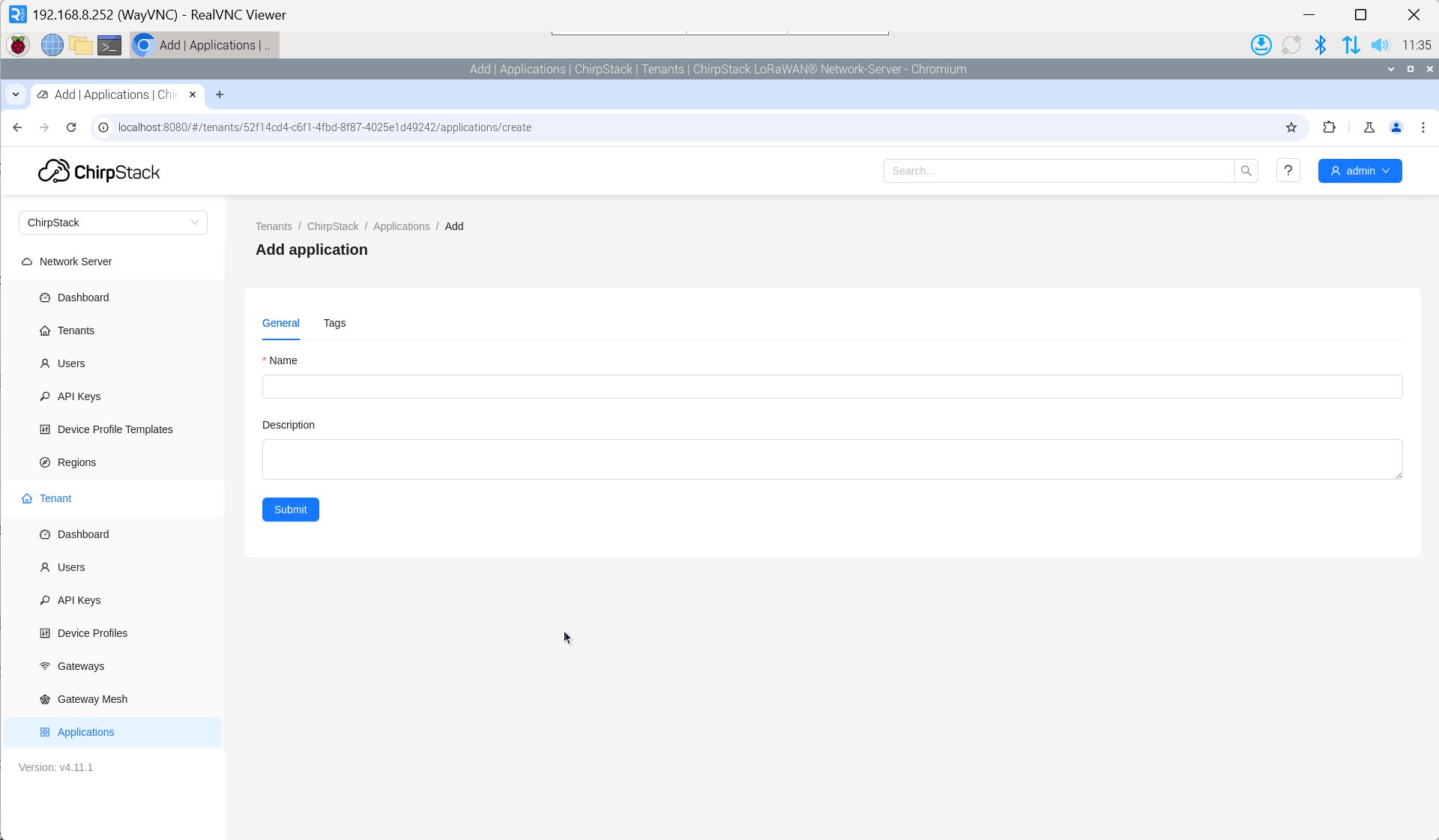
3.10.5.5 Add Application
Click "Applications" → "Add application".
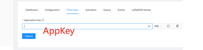
3.10.5.6 Add Device
The DevEUI and AppKey for LoRa end-device products are both provided by the LoRa device manufacturer.
- Click "Application" → "your application" → "Add device" to add the LoRa end-device.
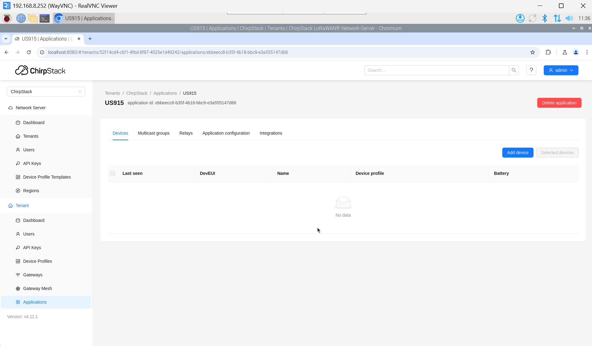
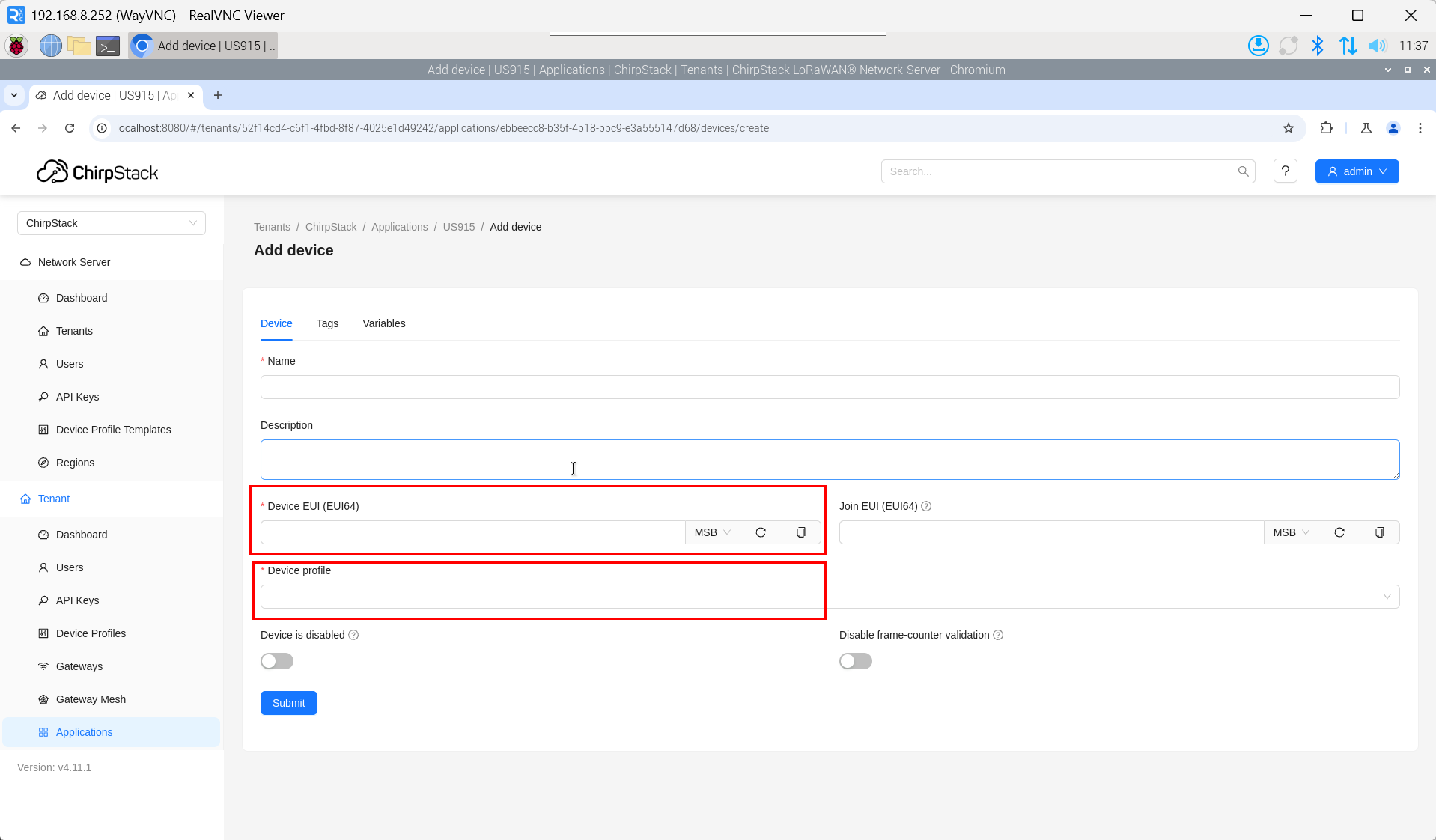
- After a few minutes, the device will appear in online status.
3.11 Encryption chip
ED-GWL2110 is equipped with ATECC608 encryption chip, which is connected to i2c-1 bus, and the default address of the device is 0x60.
atecc: https://github.com/wirenboard/atecc-util
atecc -b 1 -c 'serial'