3 Wiring Guide
3.1 Panel I/O
3.1.1 BOOT
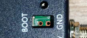
During the flashing process, short-circuit the BOOT and GND pins using jumper wires to enter flash mode. Remove the jumper wires immediately after flashing completes.
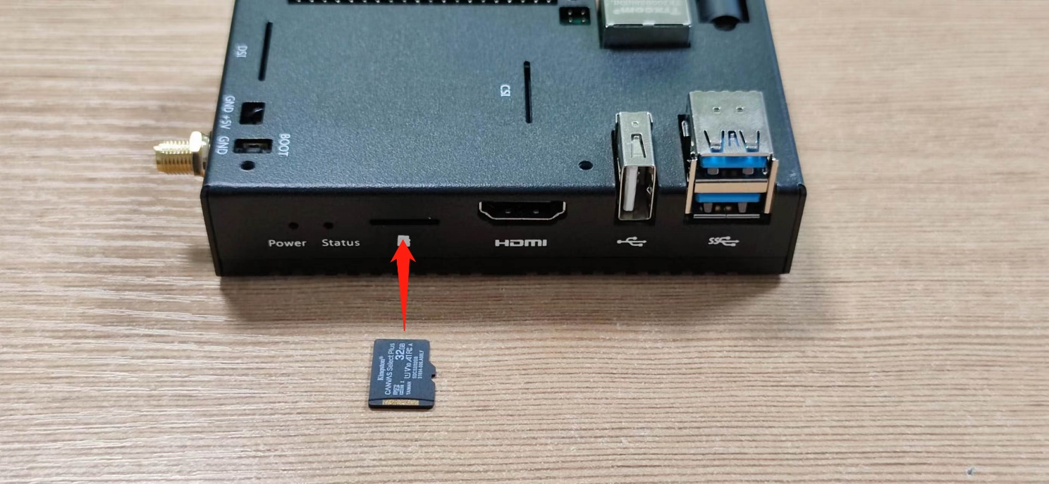
3.1.2 Micro SD Card
3.2 Internal I/O
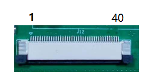
3.2.1 HDMI FPC
The FPC HDMI connector resides at position J13 on the PCB assembly and supports connection to LCD displays.
 | Pin | Definition | Pin | Definition |
|---|---|---|---|---|
| 1 | NC | 21 | GND | |
| 2 | NC | 22 | HDMI1_CLKP | |
| 3 | NC | 23 | HDMI1_CLKN | |
| 4 | NC | 24 | GND | |
| 5 | GND | 25 | BACKLIGHT_PWM | |
| 6 | USB_DP | 26 | GND | |
| 7 | USB_DM | 27 | GND | |
| 8 | GND | 28 | GND | |
| 9 | HDMI1_HPD | 29 | GND | |
| 10 | HDMI1_SCL | 30 | GND | |
| 11 | HDMI1_SDA | 31 | GND | |
| 12 | GND | 32 | LCD_PWR_EN | |
| 13 | HDMI1_TX2P | 33 | 5V | |
| 14 | HDMI1_TX2N | 34 | 5V | |
| 15 | GND | 35 | 5V | |
| 16 | HDMI1_TX1P | 36 | 5V | |
| 17 | HDMI1_TX1N | 37 | 5V | |
| 18 | GND | 38 | 5V | |
| 19 | HDMI1_TX0P | 39 | 5V | |
| 20 | HDMI1_TX0N | 40 | 5V |
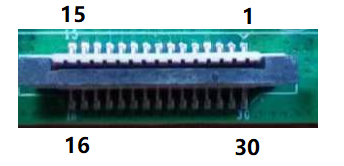
3.2.2 MIPI DSI
The FPC DSI connector resides at position J8 on the PCB assembly and supports connection to LCD displays.
 | Pin | Definition | Pin | Definition |
|---|---|---|---|---|
| 1 | GND | 9 | DSI1_D0_P | |
| 2 | DSI1_D1_N | 10 | GND | |
| 3 | DSI1_D1_P | 11 | SCL0 | |
| 4 | GND | 12 | SDA0 | |
| 5 | DSI1_CLK_N | 13 | GND | |
| 6 | DSI1_CLK_P | 14 | 3V3 | |
| 7 | GND | 15 | 3V3 | |
| 8 | DSI1_D0_N | - | - |