4 Internal Interfaces
Describes interfaces integrated within the device.
4.1 Power Output
ED-CM4NANO integrates a 2-pin wire-to-board connector (silkscreen marking: J10) delivering 5V/1A output.
4.2 Type-C USB
ED-CM4NANO integrates an internal Type-C USB interface (silkscreen marking: J75) for USB 3.0 expansion.
4.3 RTC
ED-CM4NANO features an internal RTC battery holder supporting CR1220 coin cell installation, which maintains an uninterrupted real-time clock during power cycles. The RTC clock chip resides on i2c-0 bus at address 0x51.
TIP
CR1220 batteries are excluded in some shipments due to international logistics restrictions. Install a CR1220 coin cell before using RTC functionality.
4.4 Buzzer
ED-CM4NANO incorporates an internal buzzer controlled by GPIO6:
- Active-high: Enabled
- Active-low: Disabled
4.5 HDMI FPC
ED-CM4NANO contains an FPC HDMI connector (silkscreen: J13) with reserved USB 2.0 touchscreen signals and PWM brightness control signals, supporting LCD display expansion.
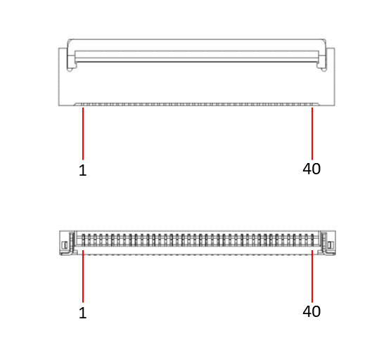 | Pin | definition | Pin | definition |
|---|---|---|---|---|
| 1 | NC | 21 | GND | |
| 2 | NC | 22 | HDMI1_CLKP | |
| 3 | NC | 23 | HDMI1_CLKN | |
| 4 | NC | 24 | GND | |
| 5 | GND | 25 | BACKLIGHT_PWM | |
| 6 | USB_DP | 26 | GND | |
| 7 | USB_DM | 27 | GND | |
| 8 | GND | 28 | GND | |
| 9 | HDMI1_HPD | 29 | GND | |
| 10 | HDMI1_SCL | 30 | GND | |
| 11 | HDMI1_SDA | 31 | GND | |
| 12 | GND | 32 | LCD_PWR_EN | |
| 13 | HDMI1_TX2P | 33 | 5V | |
| 14 | HDMI1_TX2N | 34 | 5V | |
| 15 | GND | 35 | 5V | |
| 16 | HDMI1_TX1P | 36 | 5V | |
| 17 | HDMI1_TX1N | 37 | 5V | |
| 18 | GND | 38 | 5V | |
| 19 | HDMI1_TX0P | 39 | 5V | |
| 20 | HDMI1_TX0N | 40 | 5V |
The BACKLIGHT_PWM and LCD_PWR_EN signals correspond to the following GPIO pins on the CM4:
| Signal | CM4 GPIO Name |
|---|---|
| BACKLIGHT_PWM | GPIO12 |
| LCD_PWR_EN | GPIO16 |