3 Interfaces and Connectors
Describes the interfaces and connectors on each panel of the device.
3.1 Front Panel
Interface descriptions for the front panel.
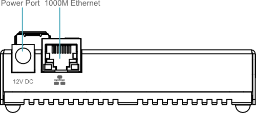
3.1.1 Power Input
ED-CM4NANO features one DC power interface with a DC Jack connector supporting 7V–18V DC input. A DC 12V power adapter is recommended. Pin definition (center-positive):

3.1.2 1000M Ethernet Port
ED-CM4NANO integrates one auto-negotiation 10/100/1000M Ethernet port (RJ45). For network connectivity, use Cat6 or higher-grade cables.
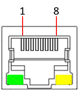 | Pin ID | Pin Name |
|---|---|---|
| 1 | TRD0+ | |
| 2 | TRD0- | |
| 3 | TRD1+ | |
| 4 | TRD2+ | |
| 5 | TRD2- | |
| 6 | TRD1- | |
| 7 | TRD3+ | |
| 8 | TRD3- |
3.2 Rear Panel
Interface and indicator descriptions for the rear panel.
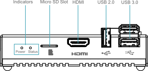
3.2.1 LED Indicators
ED-CM4NANO has two LEDs:
- Power (Red): Indicates power status
- Status (Green): Indicates system operational status
| Indicator | Function |
|---|---|
| Power | Red LED showing power on/off state |
| Status | Green LED showing system status |
3.2.2 Micro SD Card Slot
ED-CM4NANO includes a Micro SD card slot, it supports Micro SD cards for expanded user data storage.
TIP
Micro SD cards are for storage expansion only; the device does not boot from SD cards.
3.2.3 HDMI Interface
ED-CM4NANO features one HDMI interface with a standard Type-A connector, supporting connection to HDMI displays and delivering up to 4K@60Hz video output.
3.2.4 USB 2.0 Interface
ED-CM4NANO features one USB 2.0 interface with a standard Type-A connector, supporting standard USB 2.0 peripherals with transfer rates up to 480Mbps.
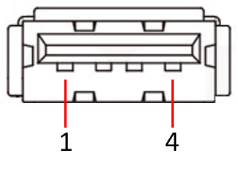 | Pin ID | Pin Name |
|---|---|---|
| 1 | 5V | |
| 2 | D- | |
| 3 | D+ | |
| 4 | GND |
3.2.5 USB 3.0 Interface
ED-CM4NANO features two USB 3.0 interfaces with standard Type-A connectors, supporting standard USB 3.0 peripherals with transfer rates up to 5Gbps.
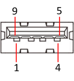 | Pin ID | Pin Name |
|---|---|---|
| 1 | 5V | |
| 2 | D- | |
| 3 | D+ | |
| 4 | GND | |
| 5 | StdA_SSRX- | |
| 6 | StdA_SSRX+ | |
| 7 | GND_DRAIN | |
| 8 | StdA_SSTX- | |
| 9 | StdA_SSTX+ |
3.3 Top Panel
Interface and connector descriptions.
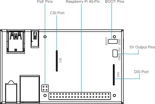
3.3.1 BOOT
ED-CM4NANO provides two dedicated BOOT and GND pins. Short-circuiting these pins enters flashing eMMC mode.
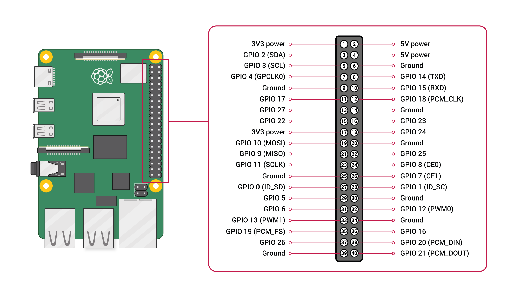
3.3.2 40-PIN Header
ED-CM4NANO integrates one standard Raspberry Pi 40-PIN GPIO header with the following pinout:
3.3.3 CSI Interface
ED-CM4NANO features one CSI interface for camera module expansion.
3.3.4 DSI Interface
ED-CM4NANO features one DSI interface for LCD display connectivity.
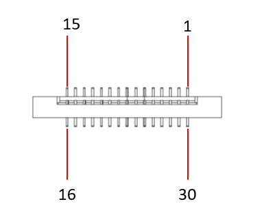 | Pin | Definition | Pin | Definition |
|---|---|---|---|---|
| 1 | GND | 9 | DSI1_D0_P | |
| 2 | DSI1_D1_N | 10 | GND | |
| 3 | DSI1_D1_P | 11 | SCL0 | |
| 4 | GND | 12 | SDA0 | |
| 5 | DSI1_CLK_N | 13 | GND | |
| 6 | DSI1_CLK_P | 14 | 3V3 | |
| 7 | GND | 15 | 3V3 | |
| 8 | DSI1_D0_N | - | - |
3.4 Side Panel
Introduce the interfaces on the side panel.
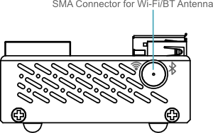
3.4.1 WiFi/BT Antenna (Optional)
ED-CM4NANO supports optional WiFi/BT antennas with dual-band 2.4GHz&5.0GHz WiFi capability.