1 Hardware Manual
This chapter introduces the safety instructions, product overview, packing list, appearance and interface.
Safety Instructions
- Do not expose this product to water, liquids, or humid environments.
- Do not expose this product to intense light sources.
- Do not place the product on conductive surfaces during use.
- During use, prevent the product from contacting metal objects to avoid short circuits caused by contact between components.
- Handle the product with care during operation to prevent mechanical or electrical damage to the circuit board and connectors.
WARNING
This product is an exposed circuit board. Conductive parts such as pins, metal connectors, and solder pads are directly accessible, making it highly vulnerable to permanent damage from electrostatic discharge (ESD). Avoid direct bare-hand contact with any metal areas on the board.
- When handling the product, the following electrostatic protection measures are recommended:
- Operators should wear a properly grounded ESD wrist strap. Anti-static gloves and clothing are also advised.
- Operate the product on an ESD-safe workbench or a surface covered with an anti-static mat.
- Use appropriate anti-static packaging, such as an anti-static bag, when moving the product.
- Always store the product in an anti-static bag or container when not in use or during transportation.
1.1 Overview
ED-CM0NANO is a single-board computer based on the Raspberry Pi CM0, featuring 512MB RAM as standard. Depending on application scenarios and user requirements, it can be configured with different eMMC storage capacities.
- Available eMMC options include 8GB and 16GB.
The ED-CM0NANO provides HDMI, USB, MIPI DSI, MIPI CSI, and a Raspberry Pi 40-pin GPIO header. It supports optional Wi-Fi (with an external antenna) for network connectivity, and integrates RTC and Watch Dog functionality. It is primarily designed for industrial control and Internet of Things (IoT) applications.
1.2 Packing List
- 1 x ED-CM0NANO Motherboard
- [Optional Wi-Fi/BT Version] 1 x FPC Wi-Fi/BT antenna
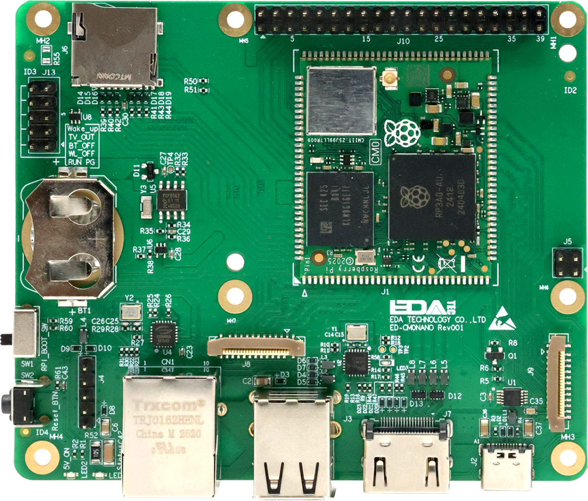
1.3 Appearance
Introduce the functions and definitions of the interfaces on the ED-CM0NANO.
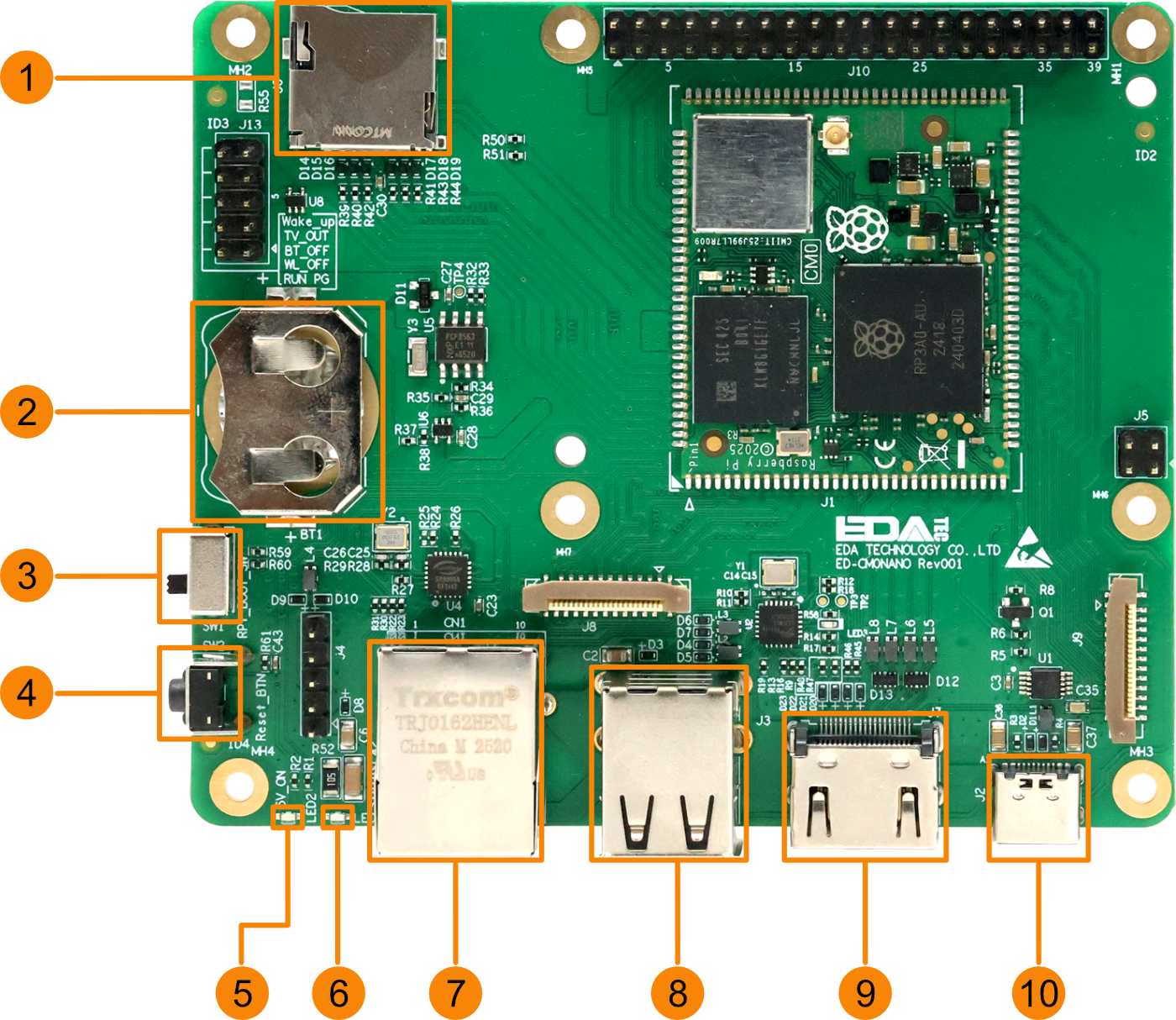
1.3.1 Panel I/O
Introduce the types and definitions of panel interfaces.
| NO. | Function Definition |
|---|---|
| 1 | 1 x Micro SD card slot, supports inserting a Micro SD card for system boot. Note: The Micro SD card slot is only compatible with the CM0Lite. |
| 2 | 1 x RTC battery base, supports installation of an RTC battery (CR2032) through this interface. |
| 3 | 1 x DIP switch, supports switching between normal operation mode and programming mode.
|
| 4 | 1 x reset button, recessed design, pressing the button restarts the device. |
| 5 | 1 x red power indicator, used to display the device's power on/off status. |
| 6 | 1 x green system status indicator, used to monitor the device's operating status. |
| 7 | 1 x adaptive 10/100M ethernet port, RJ45 connector. It can be used to access the network. |
| 8 | 2 x USB 2.0 ports, stacked Type-A connector, each supporting a maximum data transfer rate of 480Mbps. |
| 9 | 1 x HDMI port, Type-A connector, compliant with HDMI 1.3a standard, supports 1080p resolution at 30Hz and display connectivity. |
| 10 | 1 x DC input, USB Type-C connector, supports 5V input. |
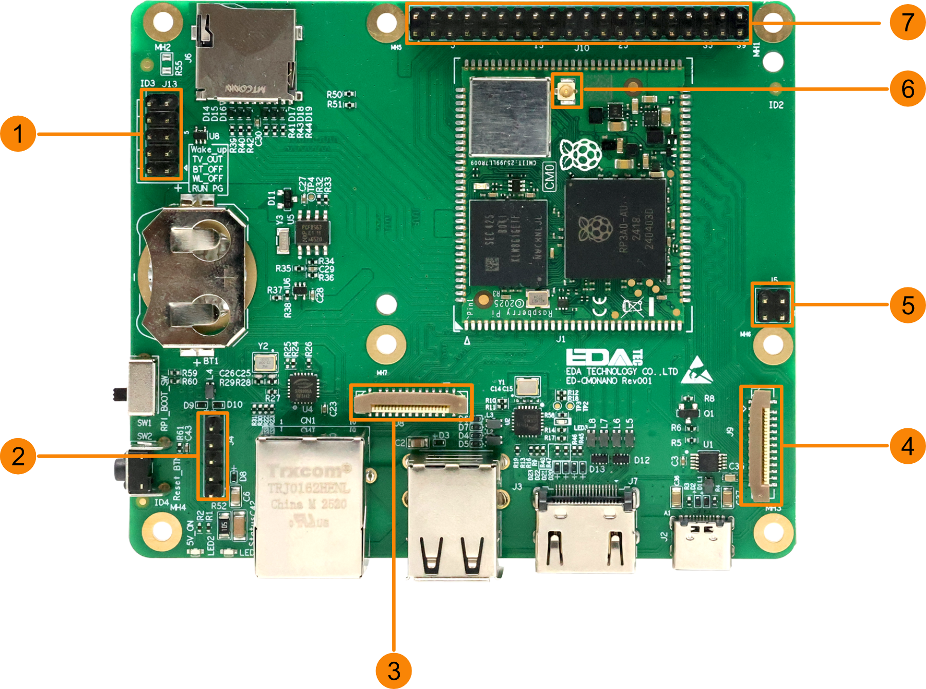
1.3.2 Expansion I/O
Introduce the types and definitions of expansion interfaces.
| NO. | Function Definition |
|---|---|
| 1 | 1 x 10-Pin Header, 2x5-pin 2.54mm pitch header. Pin definitions: 4xGND/RUN_PG/WL_ON/BT_ON/TV_OUT/RUN_PG_BUF/GLOBAL_EN, reserved for future functions.
|
| 2 | 1 x USB 2.0 interface, 1x5-pin 2.54mm pitch header. Pin definitions: VBUS/USB_DM/USB_DP/GND/NC, supports expansion of USB 2.0 interface. |
| 3 | 1 x 4-lane DSI Interface, 22-pin FPC connector, compatible with Raspberry Pi Touch Display. |
| 4 | 1 x 4-lane CSI Interface, 22-pin FPC connector, compatible with Raspberry Pi Camera modules. |
| 5 | 1 x PoE HAT Header, 2x2-pin 2.54mm pitch header, supports expansion connection for Raspberry Pi PoE HAT module. |
| 6 | 1 x IPEX-1 interface, supports connection to an external antenna. |
| 7 | 1 x Raspberry Pi 40-Pin GPIO Header, 2x20-pin 2.54mm pitch header. Pin definitions include GPIO2-GPIO27, 2x 3V3, 2x 5V, 1x ID_SD and 1x ID_SC, supports connection with Raspberry Pi standard accessories. |
1.4 Interface
Describe the definitions and functions of the various interfaces in the product.
1.4.1 Micro SD Card Slot
ED-CM0NANO includes one Micro SD card slot that supports the installation of a Micro SD card for system boot.
TIP
- The system can be booted from the Micro SD card only when the ED-CM0NANO uses the CM0Lite.
- When the ED-CM0NANO uses a CM0 with 8GB or 16GB eMMC, the Micro SD card slot is inactive.
1.4.2 Power Interface
ED-CM0NANO includes one power input interface with a USB Type-C connector, supporting 5V power input.
1.4.3 100M Ethernet Interface
ED-CM0NANO includes one adaptive 10/100M Ethernet interface with an RJ45 connector. When connecting to Ethernet, it is recommended to use a Cat6 or higher specification network cable. The pin definitions of the connector are as follows:
 | Pin ID | Pin Name |
|---|---|---|
| 1 | TX+ | |
| 2 | TX- | |
| 3 | Rx+ | |
| 4 | - | |
| 5 | - | |
| 6 | RX- | |
| 7 | - | |
| 8 | - |
1.4.4 HDMI Interface
ED-CM0NANO includes one HDMI interface, a standard Type-A port. It supports connection to HDMI displays with a maximum video output of 1080p at 30Hz.
1.4.5 USB 2.0 Interface
ED-CM0NANO includes two USB 2.0 interfaces, standard stacked Type-A ports. They support connections to standard USB 2.0 peripherals with a maximum data transfer rate of 480Mbps.
1.4.6 RTC Battery Base
ED-CM0NANO includes one RTC battery base, which supports the installation of an RTC battery through this interface.
TIP
- The supported battery model is CR2032.
- Before installing the battery, please verify the positive and negative poles of the battery, and install it according to the polarity markings (+/–) printed on the base.
1.4.7 DIP Switch
ED-CM0NANO includes one DIP switch that supports switching between normal operation mode (default) and programming mode.
- LD (switch positioned toward the RTC battery base): Enables programming mode, allowing to flash to eMMC via the Type-C USB port when connected to a PC.
- RUN (switch positioned toward the reset button): Normal operation mode, where the device functions regularly.
WARNING
The default state of the DIP switch is normal operation mode (RUN). Incorrect operation may affect the device's functionality. Please proceed with caution.
1.4.8 Antenna Interface (IPEX-1)
ED-CM0NANO includes one IPEX-1 antenna interface for connecting a Wi-Fi/BT antenna.
1.4.9 DSI (MIPI Display)
ED-CM0NANO includes one MIPI DSI interface with a 22-pin 0.5mm pitch FPC connector, supporting connection to a Raspberry Pi Tpuch Display via a 22-pin FPC cable.
TIP
The connected Raspberry Pi Touch Display requires corresponding configuration to function properly.
1.4.10 CSI (MIPI Camera)
ED-CM0NANO includes one MIPI CSI interface with a 22-pin 0.5mm pitch FPC connector, supporting connection to a Raspberry Pi Camera via a 22-pin FPC cable.
TIP
The connected Raspberry Pi Camera requires corresponding configuration to function properly.
1.4.11 PoE HAT Header
ED-CM0NANO includes one standard Raspberry Pi PoE HAT header, with a 2x2-pin 2.54mm pitch header (pin definitions are provided in the table below), supporting expansion and connection to the Raspberry Pi PoE HAT module.
 | Pin ID | Pin Name |
|---|---|---|
| 1 | POE_TAP_TR1 | |
| 2 | POE_TAP_TR2 | |
| 3 | POE_TAP_TR0 | |
| 4 | POE_TAP_TR3 |
1.4.12 Raspberry Pi 40-Pin GPIO Header
ED-CM0NANO includes one standard Raspberry Pi 40-Pin GPIO header, labeled as J1 on the board. The detailed pin definitions are provided in the table below.
 | Pin ID | Pin Name | Pin ID | Pin Name |
|---|---|---|---|---|
| 1 | +3.3v | 2 | +5V | |
| 3 | GPIO2 | 4 | +5V | |
| 5 | GPIO3 | 6 | GND | |
| 7 | GPIO4 | 8 | GPIO14 | |
| 9 | GND | 10 | GPIO15 | |
| 11 | GPIO17 | 12 | GPIO18 | |
| 13 | GPIO27 | 14 | GND | |
| 15 | GPIO22 | 16 | GPIO23 | |
| 17 | +3.3V | 18 | GPIO24 | |
| 19 | GPIO10 | 20 | GND | |
| 21 | GPIO9 | 22 | GPIO25 | |
| 23 | GPIO11 | 24 | GPIO8 | |
| 25 | GND | 26 | GPIO7 | |
| 27 | ID_SD | 28 | ID_SC | |
| 29 | GPIO5 | 30 | GND | |
| 31 | GPIO6 | 32 | GPIO12 | |
| 33 | GPIO13 | 34 | GND | |
| 35 | GPIO19 | 36 | GPIO16 | |
| 37 | GPIO26 | 38 | GPIO20 | |
| 39 | GND | 40 | GPIO21 |
1.4.13 USB 2.0 Header
ED-CM0NANO includes one USB 2.0 header with a 1x5-pin 2.54mm pitch header. The pin definitions are VBUS/USB_DM/USB_DP/GND/NC (see table below), supporting expansion of USB 2.0 interface.
 | Pin ID | Pin Name |
|---|---|---|
| 1 | VBUS | |
| 2 | USB_DM | |
| 3 | USB_DP | |
| 4 | GND | |
| 5 | NC |
1.4.14 10-Pin Header
ED-CM0NANO includes one 10-pin header with a 2x5-pin 2.54mm pitch header. The pin definitions are 4xGND/RUN_PG/WL_ON/BT_ON/TV_OUT/RUN_PG_BUF/GLOBAL_EN (see table below), reserved for future functions.
- Short GND (Pin 1) and RUN_PG (Pin 2): Shuts down the ED-CM0NANO.
- Short GND (Pin 3) and WL_ON (Pin 4): Disables Wi-Fi functionality.
- Short GND (Pin 5) and BT_ON (Pin 6): Disables Bluetooth functionality.
- Connect a button between RUN_PG_BUF (Pin 9) and GLOBAL_EN (Pin 10): Can be used to wake the ED-CM0NANO from sleep mode.
 | Pin ID | Pin Name |
|---|---|---|
| 1 | GND | |
| 2 | RUN_PG | |
| 3 | GND | |
| 4 | WL_ON | |
| 5 | GND | |
| 6 | BT_ON | |
| 7 | GND | |
| 8 | TV_OUT | |
| 9 | RUN_PG_BUF | |
| 10 | GLOBAL_EN |