1 Hardware Manual
This chapter introduces the product overview, packing list, appearance, indicator and interface.
1.1 Overview
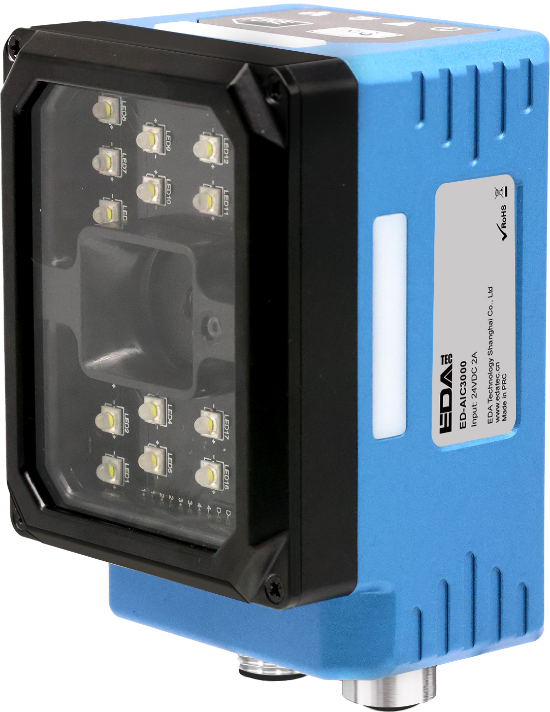
The ED-AIC3000 is an industrial smart camera based on the Raspberry Pi CM5 core module, featuring 12-megapixel imaging capability and a sampling rate of up to 60 FPS. To accommodate different application scenarios and requirements, the device supports flexible storage configurations:
- RAM options include 2GB, 4GB, and 8GB
- eMMC flash storage options include 16GB, 32GB, and 64GB
The ED-AIC3000 integrates a modular lighting system and is equipped with an M12 fixed-focus lens (with liquid lens zoom capability). It supports both bright-field and dark-field illumination modes, enabling optimal lighting effects on normal, etched, high-gloss, and textured surfaces to enhance imaging contrast and defect detection.
The ED-AIC3000 provides power interfaces, I/O interfaces, an RS232 serial port, and a Gigabit Ethernet port. All interfaces utilize rugged M12 aviation connectors, supporting Ethernet connectivity and real-time data transmission. It is primarily suited for demanding applications such as machine vision inspection, AI visual analysis, industrial automation, and quality control.
1.2 Packing List
1 x ED-AIC3000 Unit
1.3 Appearance
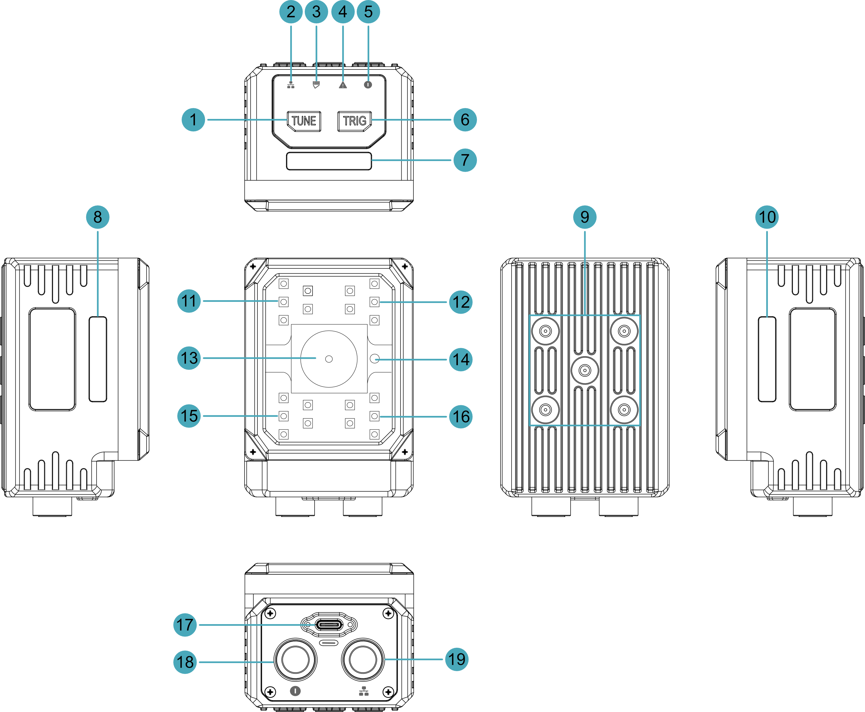
Introduce the functions and definitions of product interfaces, buttons and indicators.
| NO. | Function Definition |
|---|---|
| 1 | 1 x TUNE button, one-touch autofocus button or user-defined button. |
| 2 | 1 x Network connection indicator, which is used to check the status of the network connection. |
| 3 | 1 x working status indicator, which is used to check the working status of the device. |
| 4 | 1 x System fault indicator, which is used to check if a system fault occurs. |
| 5 | 1 x Power indicator, which is used to check the power-on status of the device. |
| 6 | 1 x TRIG button, using to camera triggering or user-defined one-touch button. |
| 7, 8, 10 | 3 x RGB lights (1 set), lights can be set to red, green, blue, yellow and white, user customizable. |
| 9 | 5 x M4 screw holes for bracket mounting. |
| 11, 12, 15, 16 | 4 x light sources, using for supplementary lighting when the device is working. |
| 13 | 1 x M12 Lens, using to take photos. |
| 14 | 1 x laser light, red circular spot, for image positioning. |
| 17 | 1 x USB type-c port, using to flash to eMMC. |
| 18 | 1 x power interface, including power input port, I/O ports and RS232 serial port, using M12 12-Pin aviation connector. |
| 19 | 1 x communication interface, Gigabit Ethernet interface, using M12 8-Pin A-code aviation connector for access to Ethernet. |
1.4 Button
The ED-AIC3000 device include 2 buttons, an TUNE button and a TRIG button.
- The TUNE button has "TUNE" printed on the case. Pressing the button can realize one-touch automatic focus, and it supports that users to customize its functions.
- The TRIG button has "TRIG" printed on the case. Pressing the button can trigger the camera, and it support that users to customize its functions.
Pin Definition
The button pins are defined as follows:
| Button | CM5 Pin |
|---|---|
| TUNE button | GPIO20 |
| TRIG button | GPIO12 |
1.5 Indicator
This section describes the various states and meanings of the indicators on the ED-AIC3000 device.
| Indicator | Status | Description |
|---|---|---|
| Network connection indicator | Yellow solid | The Ethernet has been connected normally |
| Off | No Ethernet connection | |
| Working status indicator | Green solid (controlled and set to ON via SDK) | The system is working normally |
| Red solid (controlled and set to ON via SDK) | System working status is abnormal | |
| System fault indicator | On | System failure |
| Off | The system has not failed | |
| Power indicator | Red solid | The device is powered on |
| Off | The device is powered off |
Pin Definition
| Indicator | CM5 Pin |
|---|---|
| Power indicator | N/A |
| System fault indicator | GPIO21 |
| Working status indicator | GPIO7 (abnormal) GPIO16 (normal) |
| Network connection indicator | N/A |
1.6 Interface
This section describes the definition and function of each interface in the product.
1.6.1 Power & I/O Interface
The ED-AIC3000 device feature a Power & I/O Interface with a 12-pin M12 aviation connector. This interface integrates:
- 1 power input
- 1 serial port (RS232)
- 1 digital input (DI)
- 2 digital outputs (DOs)
The Power & I/O cable connects to this interface:
- One end is terminated with an M12 connector for camera integration.
- The other end consists of bare wires for connecting to power, DI, DO, and RS232 devices.
The pinout definitions for the M12 connector and the corresponding bare wire assignments are detailed in the following table:
M12 Pin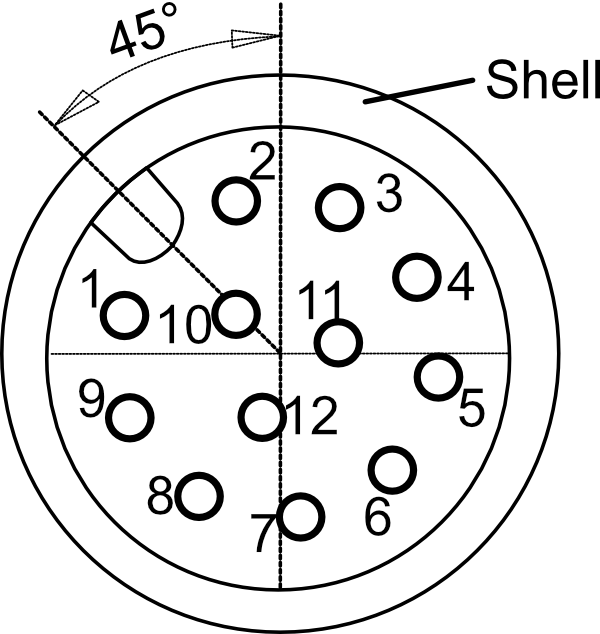 | Bare Wire Color | Definition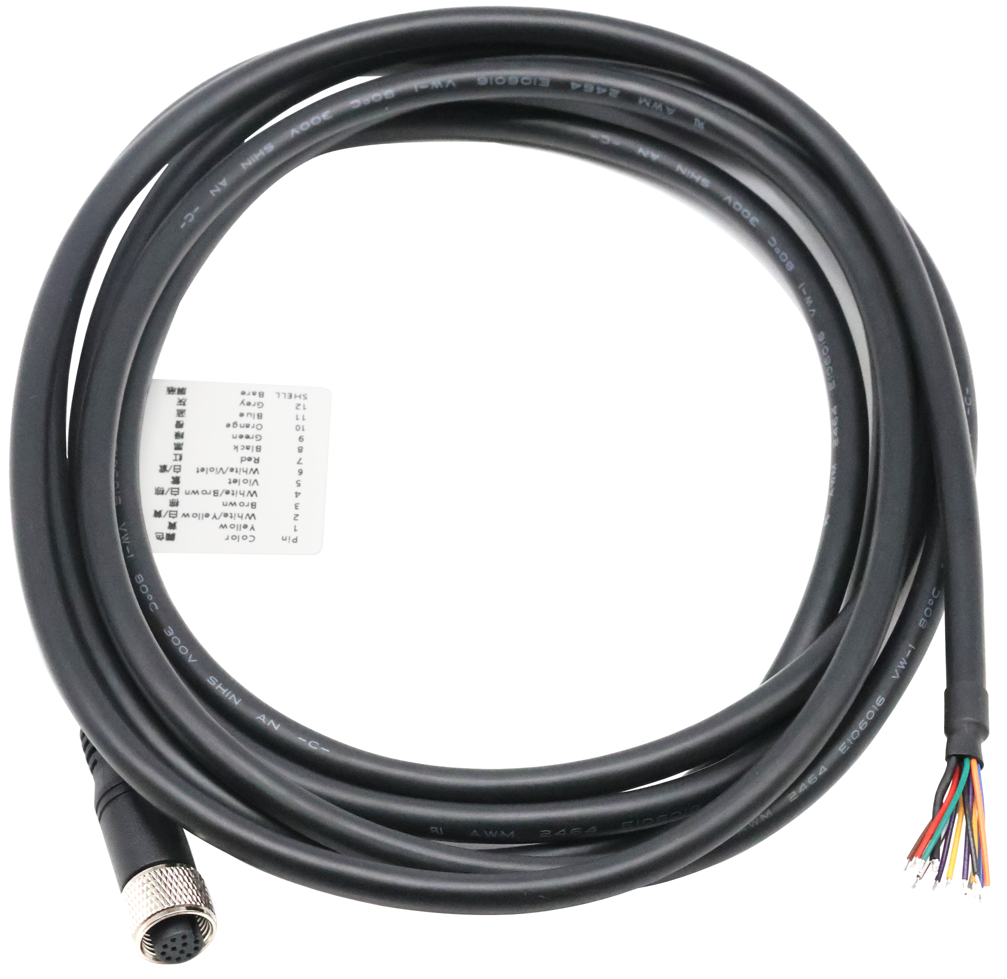 |
| 1 | Yellow | DC- |
| 2 | White/Yellow | DC+ |
| 3 | Brown | COMMON_IN |
| 4 | White/Brown | DI_1 |
| 5 | Purple | Trigger |
| 6 | White/Purple | COMMON_OUT |
| 7 | Red | External Strobe |
| 8 | Black | DO_1 |
| 9 | Green | DO_2 |
| 10 | Orange | RS232_GND |
| 11 | Blue | RS232_TX |
| 12 | Gray | RS232_RX |
| Shell | Black (Thick) | PE |
One DI (Digital Input) and 2 DO (Digital Output) channels correspond to the CM5's GPIO pins, as detailed in the following table:
| Signal | CM5 Pin |
|---|---|
| DI1 | GPIO17 |
| DO1 | GPIO22 |
| DO2 | GPIO27 |
TIP
- The thickest black bare wire is PE.
- For Raspberry Pi HQ Camera, Pins 5 and 7 of the M12 connector are undefined.
- During installation, ensure that wire colors align with pin definitions and properly connect the PE to the ground terminal to guarantee safety and signal integrity.
- If there are unused bare wires during wiring, cut off the exposed metal ends or insulate them with electrical tape.
WARNING
Strictly follow the wiring instructions below to connect the power & I/O cable; incorrect wiring may result in device damage.
1.6.1.1 Power Connection
For the power & I/O cable:
- White/Yellow and Yellow wires connect to the positive (+) and negative (-) terminals of the external power supply, respectively.
- The thick black wire (PE) connects to the ground terminal.
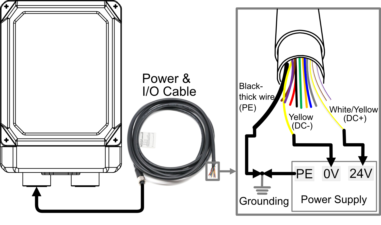
WARNING
- Device Power Supply: DC24V (±10%). It is recommended to use a DC 24V 2A power adapter.
- When connecting the power cable, connect the PE in the bare wires and the external power supply's PE to ground terminal to ensure proper grounding.
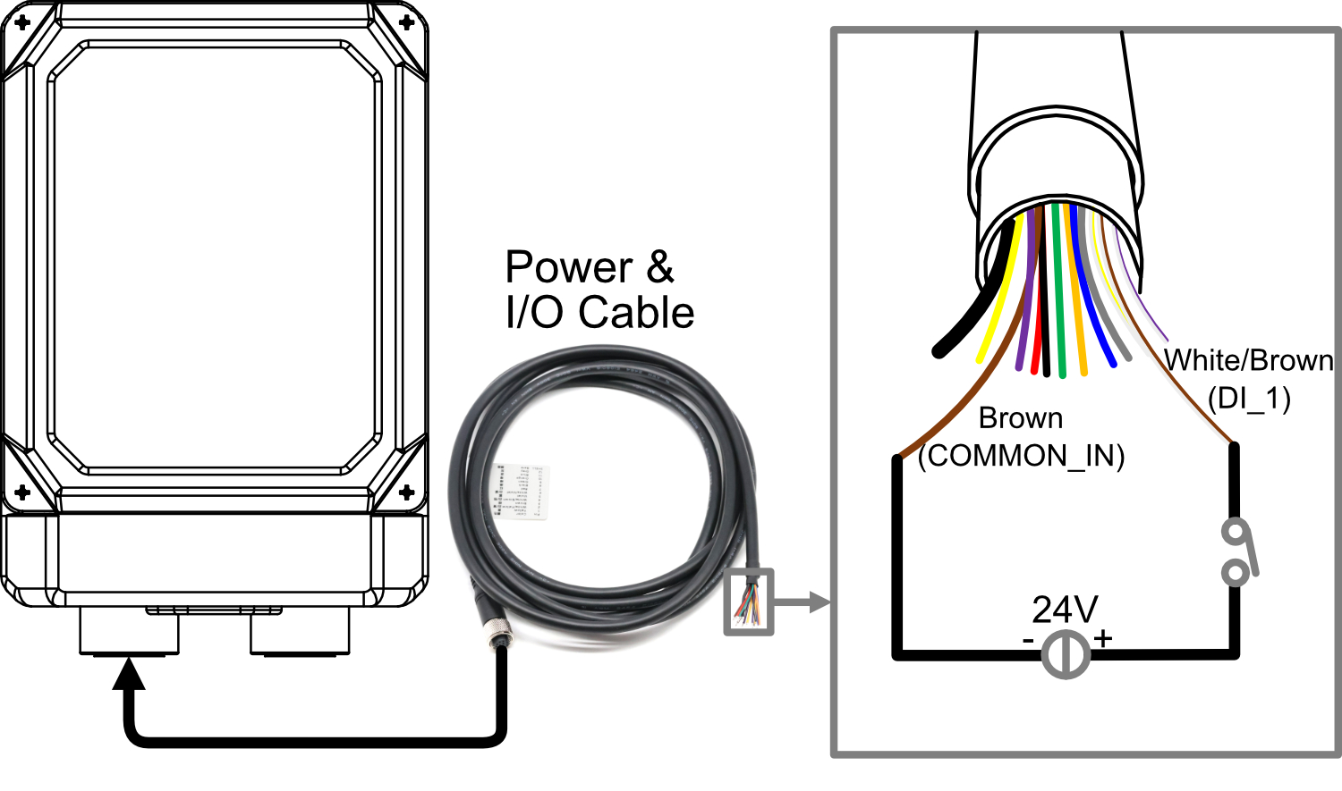
1.6.1.2 DI Connection
For the power & I/O cable:
- White/Brown is DI Channel 1.
- Brown is the DI common terminal (COMMON_IN).
- Supports NPN-type or PNP-type sensor.
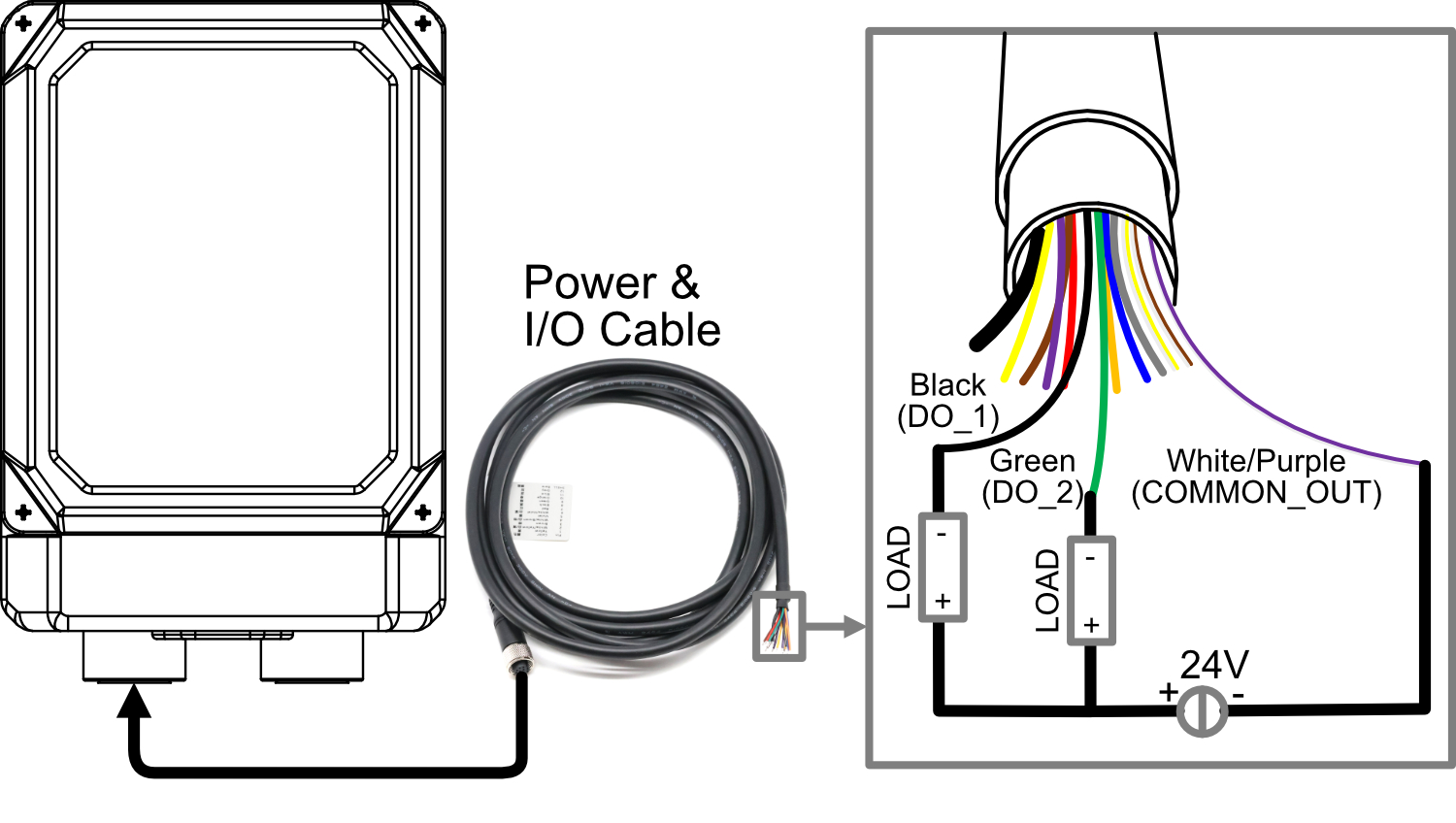
1.6.1.3 DO Connection
For the power & I/O cable:
- Black and green wires correspond to the 2 DO channels.
- White/purple wire serves as the common terminal for the DO channels.
DO Specifications:
- Single-channel load: 0.25A (max).
- Total current for 2 consecutive channels: 0.5A (max).
- Supported load types: Resistive loads, lamp loads, and inductive loads.
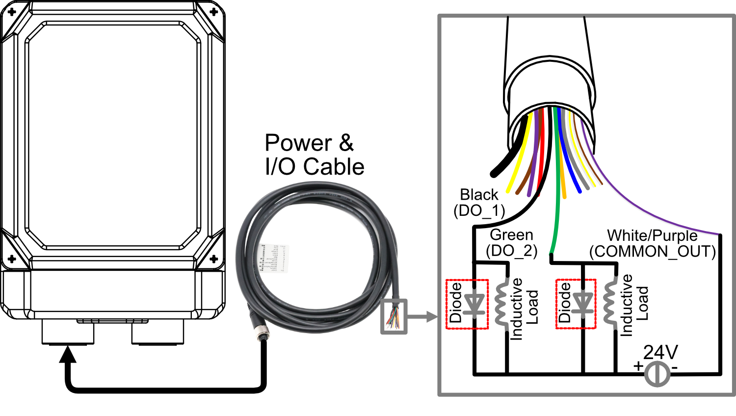
WARNING
- Do not connect the white/purple wire (COMMON_OUT) to the 24V positive terminal.
- If an inductive load is connected to the DO channel, it is recommended to add a Diode in the circuit (as shown in the figure below) for protection. Select an appropriate Diode based on the specifications of the inductive load.
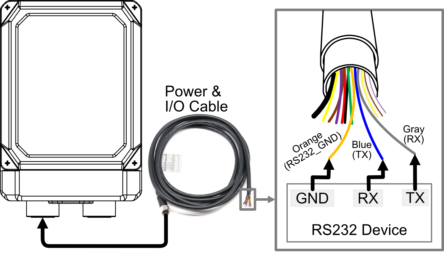
1.6.1.4 RS232 Connection
For the power & I/O cable:
- Orange: RS232_GND
- Blue: RS232_TX
- Gray: RS232_RX
- Compatible with RS232 devices.
1.6.2 Communication interface
ED-AIC3000 device include 1 communication interface with M12 8-Pin aviation connector.
Pin Definition
The pin definitions are as follows:
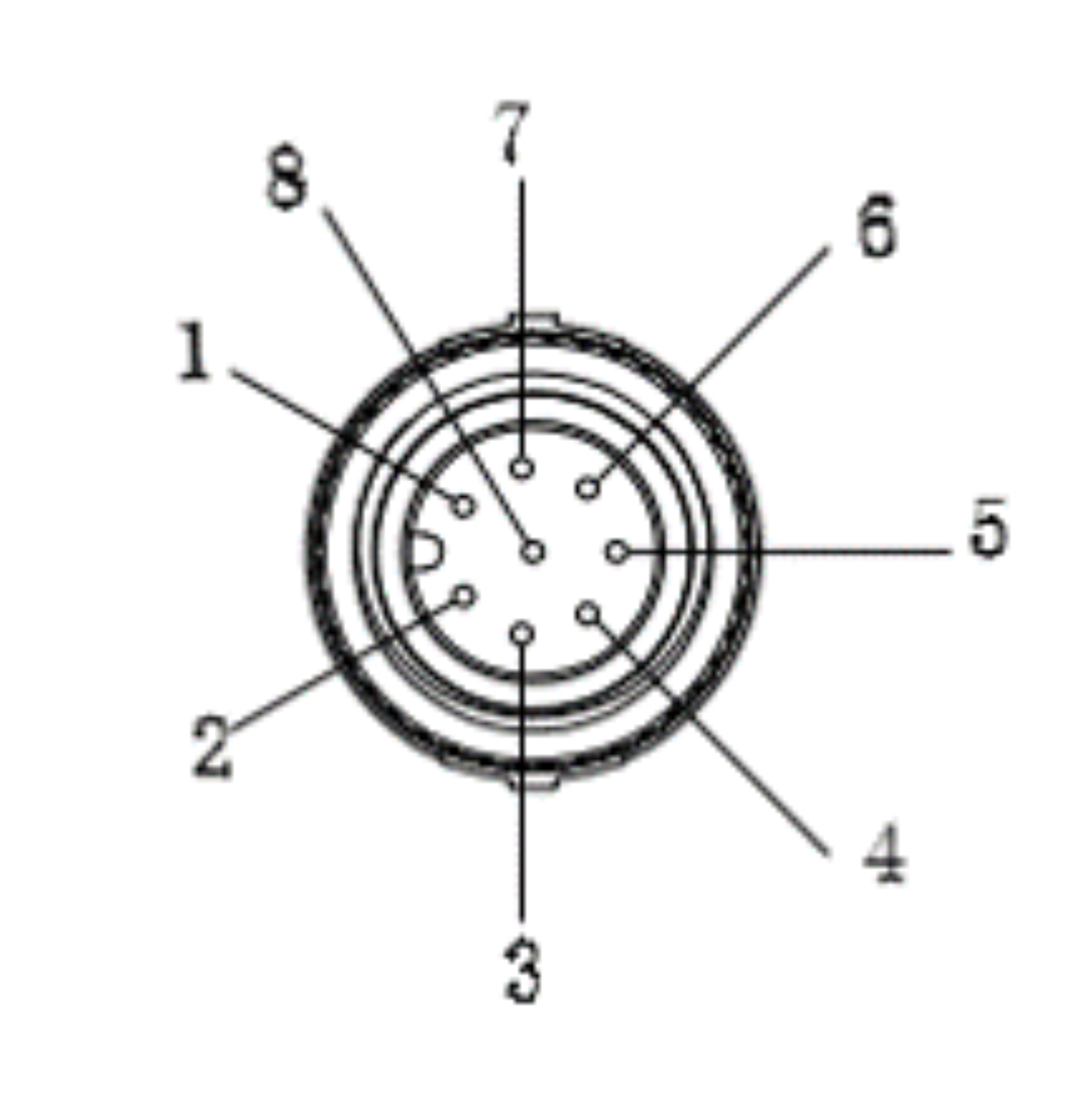 | Pin ID | Pin Name |
| 1 | TRD0+ | |
| 2 | TRD0- | |
| 3 | TRD1+ | |
| 4 | TRD2+ | |
| 5 | TRD2- | |
| 6 | TRD1- | |
| 7 | TRD3+ | |
| 8 | TRD3- |
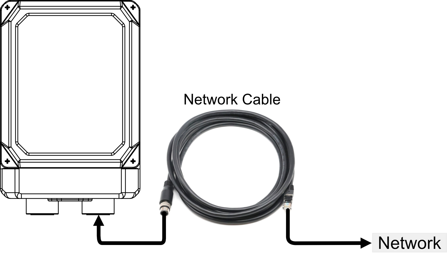
Cable Connection
The communication interface is used to connect an Ethernet cable, enabling the device to access the network. One end of the cable is terminated with an M12 connector for connecting to the Camera, while the other end features an RJ45 connector for network integration.
1.6.3 USB-C interface
ED-AIC3000 include a USB Type-C interface, which supports flashing to eMMC by connecting to a PC.
1.7 Light source and lens
The ED-AIC3000 series equipment consists of four light sources and a lens.
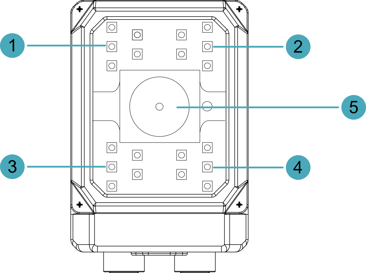
| NO. | Description |
|---|---|
| 1 | Light source part 1 (TopLeft), supports individual enabling and disabling. |
| 2 | Light source part 2 (TopRight), supports individual enabling and disabling. |
| 3 | Light source part 3 (BottomLeft), supports individual enabling and disabling. |
| 4 | Light source part 4 (BottomRight), supports individual enabling and disabling. |
| 5 | Lens, M12 fixed focal length lens with liquid module zoom. |
1.8 RGB Lights
ED-AIC3000 device contain 3 RGB lights, 3 RGB lights as a group. It supports to set the lights as red, green, blue, yellow or white through software, the default is off, users can customize according to the actual needs.
TIP
3 RGB lights as a group, only support simultaneous setting.