1 Hardware Manual
This chapter introduces the safety instructions, product overview, packing list, appearance, button, indicator and interfaces.
Safety Instructions
- Do not expose this product to water, liquids, or humid environments.
- Do not expose this product to intense light sources.
- Do not place the product on conductive surfaces during use.
- During use, prevent the product from contacting metal objects to avoid short circuits caused by contact between components.
- Handle the product with care during operation to prevent mechanical or electrical damage to the circuit board and connectors.
WARNING
This product is an exposed circuit board. Conductive parts such as pins, metal connectors, and solder pads are directly accessible, making it highly vulnerable to permanent damage from electrostatic discharge (ESD). Avoid direct bare-hand contact with any metal areas on the board.
- When handling the product, the following electrostatic protection measures are recommended:
- Operators should wear a properly grounded ESD wrist strap. Anti-static gloves and clothing are also advised.
- Operate the product on an ESD-safe workbench or a surface covered with an anti-static mat.
- Use appropriate anti-static packaging, such as an anti-static bag, when moving the product.
- Always store the product in an anti-static bag or container when not in use or during transportation.
1.1 Overview
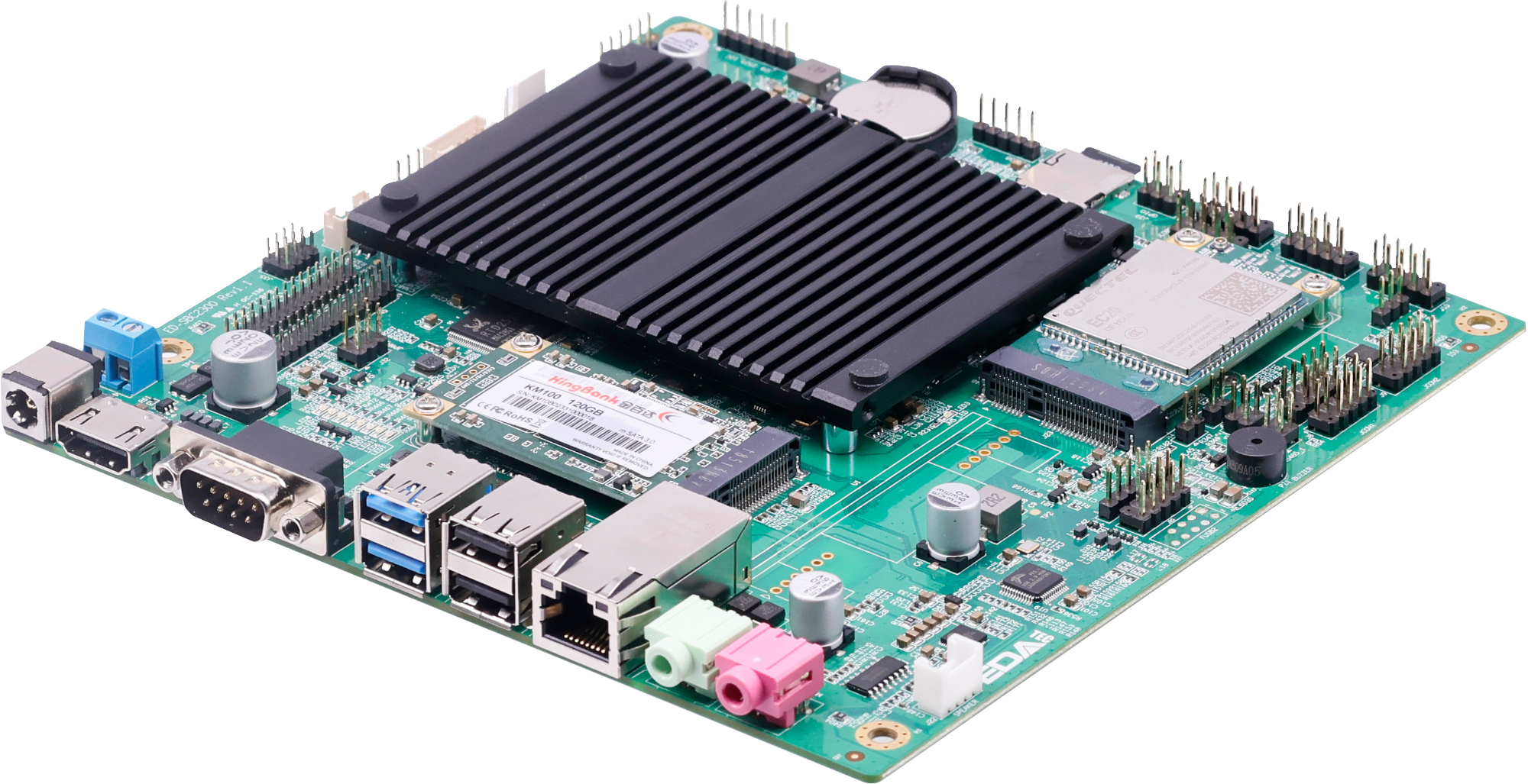
ED-SBC2300 series is a Mini-ITX industrial single board computer based on Raspberry Pi CM4. According to different application scenarios and user needs, different specifications of RAM and eMMC computer systems can be selected.
- Options for 1GB, 2GB, 4GB and 8GB RAM
- Options for 8GB, 16GB and 32GB eMMC storage
ED-SBC2300 series provides common interfaces such as HDMI, USB, Ethernet, RS232 and RS485, and supports access to the network through Wi-Fi, Ethernet and 4G. It supports Micro SD Card and mSATA SSD storage expansion, integrates RTC, EEPROM and encryption chip, and provides ease of use and security of products, which are mainly used in industrial control and IOT.
ED-SBC2300 series includes:
- ED-SBC2310
- ED-SBC2311
- ED-SBC2320
- ED-SBC2321
And the corresponding main configurations are as follows.
| Model | Configuration |
|---|---|
| ED-SBC2310 | 1 x 1000M Ethernet, 2 x USB 2.0, 2 x USB 3.0 |
| ED-SBC2311 | 2 x 1000M Ethernet, 2 x USB 3.0 |
| ED-SBC2320 | 1 x 1000M Ethernet, 2 x USB 2.0, 2 x USB 3.0, 1 x LVDS display port, Audio, Speaker |
| ED-SBC2321 | 2 x 1000M Ethernet, 2 x USB 3.0, 1 x LVDS display port, Audio, Speaker |
1.2 Packing List
- 1x ED-SBC2300 Unit
1.3 Appearance
Introduce the functions and definitions of interfaces on each panel.
1.3.1 Panel Interface
Introduce panel interface types and definitions.
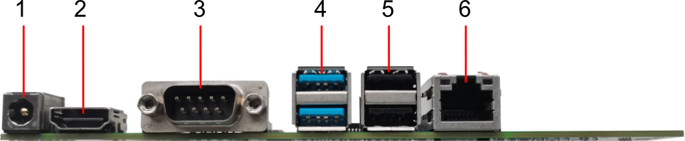
Panel of Single Ethernet Port -ED-SBC2310:
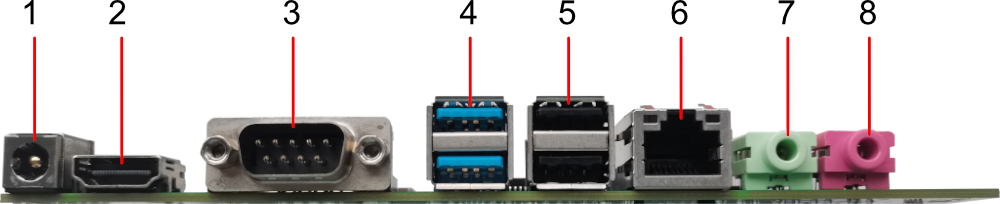
Panel of Single Ethernet Port-ED-SBC2320:
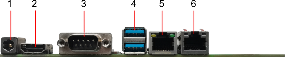
Panel of Dual Ethernet Port-ED-SBC2311:
Panel of Dual Ethernet Port-ED-SBC2321:
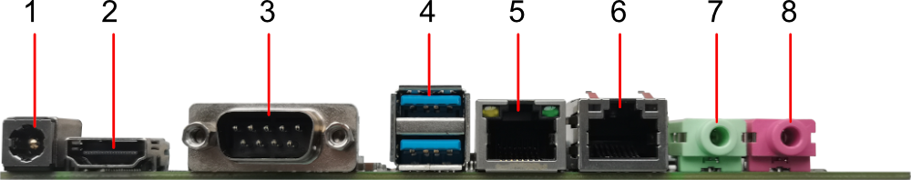
| NO. | Function Definition |
|---|---|
| 1 | 1 x DC input, DC Jack connector (2-Pin 3.5mm pitch phoenix terminal is optional), supporting 9V~36V input. |
| 2 | 1 x HDMI port, type A connector, which is compatibles with HDMI 2.0 standard and supports 4K 60Hz. |
| 3 | 1 x RS232, DB9 male connector, single board debug serial port for debugging. |
| 4 | 2 x USB 3.0, double-layer type-A connector, each channel supports up to 5Gbps transmission rate. |
| 5 | Choose one between 2 x USB 2.0 ports and 1 x 1000M Ethernet port.
|
| 6 | 1 x adaptive 10/100/1000M ethernet port, RJ45 connector. It can be used to access the network. PoE can be supported through optional expansion module. The maximum power of PoE is 60W and it is compatible with IEEE 802.3bt standard. |
| 7 | 1 x LINE Output, 3.5mm audio jack connector (green), stereo audio output. Note: Only ED-SBC2320 and ED-SBC2321 contains this interface. |
| 8 | 1 x MIC Input, 3.5mm audio jack connector (red), which can connect to microphone. Note: Only ED-SBC2320 and ED-SBC2321 contains this interface. |
1.3.1.1 Power Supply
ED-SBC2300 series single-board include 1 power input, DC Jack connector (DC 5.5x2.5 socket) is used by default, optional 2-Pin 3.5mm pitch phoenix terminal is available to support 9V~36V input, the pin definition is as follows.
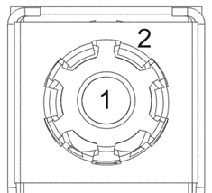 | Pin ID | Pin Name |
|---|---|---|
| 1 | 9V~36V | |
| 2 | GND |
1.3.1.2 HDMI
ED-SBC2300 series single-board include one HDMI interface, standard type-A connector. It supports connecting HDMI monitor and maximum 4Kp60 video output.
1.3.1.3 COM
ED-SBC2300 series single-board includes one COM interface and DB9 male connector, which is the debugging serial port of single board by default for debugging.
Pin Definition
Pins are defined as follows:
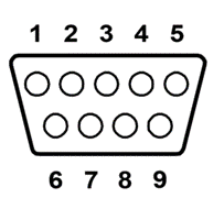 | Pin ID | Pin Name |
|---|---|---|
| 1 | NC | |
| 2 | DB9_RS232_RX | |
| 3 | DB9_RS232_TX | |
| 4 | NC | |
| 5 | GND | |
| 6~9 | NC |
The pin names of the RS232 interface corresponding to CM4 are as follows:
| Signal | CM4 GPIO Name | CM4 Pin Out |
|---|---|---|
| DB9_RS232_RX | GPIO15 | CM4_UART_RXD0 |
| DB9_RS232_TX | GPIO14 | CM4_UART_TXD0 |
1.3.1.4 USB 3.0
ED-SBC2300 series single-board includes 2 USB 3.0 interfaces and double-layer standard type-A connectors. It supports the connection of standard USB 3.0 peripherals, and supports the maximum transmission rate of 5Gbps.
1.3.1.5 USB 2.0
ED-SBC2300 series single-board includes 2 USB 2.0 interfaces and double-layer standard type-A connectors. It supports the connection of standard USB 2.0 peripherals, and supports the maximum transmission rate of 480Mbps.
TIP
Only ED-SBC2320 and ED-SBC2321 contains this interface.
1.3.1.6 1000M Ethernet(ETH1)
TIP
Only ED-SBC2320 and ED-SBC2321 contains this interface.
ED-SBC2300 series single-board include 1 adaptive 10/100/1000M Ethernet interface (converted from 2 x USB 2.0 to a network port), using RJ45 connector, and it is recommended to use Cat6 and above specification network cable with it when accessing Ethernet. The corresponding pin definitions of the terminals are as follows:
 | Pin ID | Pin Name |
|---|---|---|
| 1 | TX1+ | |
| 2 | TX1- | |
| 3 | TX2+ | |
| 4 | TX2- | |
| 5 | TX3+ | |
| 6 | TX3- | |
| 7 | TX4+ | |
| 8 | TX4- |
1.3.1.7 1000M Ethernet(ETH0)
ED-SBC2300 series single-board include 1 adaptive 10/100/1000M Ethernet interface, using RJ45 terminals, with the expansion module can support PoE power supply, when accessing Ethernet, it is recommended to use Cat6 and above specifications of the network cable to work with. The corresponding pin definitions of the terminals are as follows:
| Pin ID | Pin Name |
|---|---|---|
| 1 | TX1+ | |
| 2 | TX1- | |
| 3 | TX2+ | |
| 4 | TX2- | |
| 5 | TX3+ | |
| 6 | TX3- | |
| 7 | TX4+ | |
| 8 | TX4- |
1.3.1.8 LINE OUT
The ED-SBC2300 series single-board include 1 audio output that supports stereo output using a green 3.5mm audio connector.
TIP
Only ED-SBC2320 and ED-SBC2321 contains this interface.
1.3.1.9 MIC IN
The ED-SBC2300 series single-board include 1 MIC input that supports microphone input using a red 3.5mm audio connector.
TIP
Only ED-SBC2320 and ED-SBC2321 contains this interface.
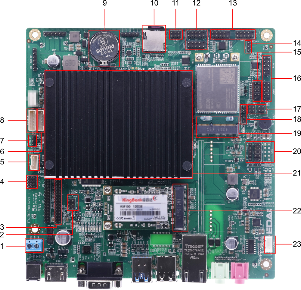
1.3.2 Extended Interface
Introduces extended interface types and definitions.
| NO. | Function Definition |
|---|---|
| 1 | 1 x Power IN, 2-Pin 5mm pitch connector, reserved power input port, supporting 9V~36V input. The signals are defined as DC IN/GND |
| 2 | 1 x LVDS Screen Voltage Control port,3x2-Pin 2.54mm pitch pin header,by choosing to connect different pins to set different power supply voltages, which can meet the power needs of various LVDS screens Note: Only ED-SBC2320 and ED-SBC2321 contains this interface. |
| 3 | 1 x LVDS display port, 2 x 15-Pin 2.54mm pitch pin header, expandable to connect LVDS display, resolution support up to 1080p 60Hz Note: Only ED-SBC2320 and ED-SBC2321 contains this interface. |
| 4 | 1 x LVDS output resolution adjustment port, 3x4-Pin 2.0mm pitch pin header, supporting software setting of pin level to adapt to different screen sizes and specifications Note: Only ED-SBC2320 and ED-SBC2321 contains this interface. |
| 5 | 1 x LVDS screen brightness control port, 4-Pin 2.0mm pitch WTB connector, by choosing to connect different pins to control LVDS screen brightness. Note: Only ED-SBC2320 and ED-SBC2321 contains this interface. |
| 6 | 1 x Backlight Control port, 6-Pin 2.0mm Pitch WTB Connector, Integrated On-Board Backlight Driver Circuitry and Supports Backlight Brightness Switching and Adjustment Note: Only ED-SBC2320 and ED-SBC2321 contains this interface. |
| 7 | 1 x RPI_BOOT port, 3-Pin 2.54mm pitch pin header, which can make the single board enter RPI BOOT mode by shorting 2 pins. |
| 8 | 1 x Backlight power port, 6-Pin 2.0mm pitch WTB connector for 12V backlight power, PWM backlight enable and PWM backlight adjustment channels Note: Only ED-SBC2320 and ED-SBC2321 contains this interface. |
| 9 | 1 x RTC battery base, supporting the installation of CR2032 button cell. |
| 10 | 1 x Micro SD card slot, which supports the installation of SD card and is used to store user data. |
| 11 | 1 x GPIO Pin Header, 2x3-Pin 2.54mm pitch pin header, used to lead out the extended GPIO. |
| 12 | 2 x RS232, 2x5(9)-Pin 2.54mm pitch pin header, used to expand serial port. |
| 13 | 2 x RS232, 2x5(9)-Pin 2.54mm pitch pin header, used to expand serial port. |
| 14 | 1 x Auto-boot after powering on port,3-Pin 2.54mm pitch pin header,by choosing to connect different pins to enable/disable this function. |
| 15 | 1 x Front panel port, 2 x 5-Pin 2.54mm pitch pin header for extended connectivity to power button, reset button, HDD indicator and power indicator |
| 16 | 2 x RS232, 2x5(9)-Pin 2.54mm pitch pin header, used to expand serial port. |
| 17 | 2 x RS485, 2x2-Pin 2.54mm pitch pin header, used to expand RS485 port. |
| 18 | 2 x RS485 terminal resistor port, 2-Pin 2.54mm pitch pin header, insert jumper cap to enable the terminal resistor |
| 19 | 1 x PCIe port, support optional 4G module for 4G function. The location where the module is mounted contains a Nano SIM slot for the SIM card that acquires the 4G signal. |
| 20 | 3 x USB 2.0 or 5 x USB 2.0, different quantities correspond to different product models.
|
| 21 | 1 x Passive Cooler (optional) for single board cooling. |
| 22 | 1 x mSATA port, Mini PCIe connector for external mSATA hard drives. |
| 23 | 1 x power amplifier output, 4-Pin 2.0mm WTB connector, dual-channel stereo output. Note: Only ED-SBC2320 and ED-SBC2321 contains this interface. |
1.3.2.1 Power Supply
ED-SBC2300 series single-board include an extended power input port, 2-Pin 5.0mm pitch connector, reserved for single-board power supply, supporting 9V~36V input. The pin definitions are as follows:
 | Position Silkscreen | Pin ID | Pin Name |
|---|---|---|---|
| J47 | 1 | 9V~36V | |
| 2 | GND |
1.3.2.2 Micro SD Slot
ED-SBC2300 series single-board integrates a Micro SD card slot, which supports the installation of SD card for storing user data.
 | Position Silkscreen |
|---|---|
| J6 | |
1.3.2.3 RTC Battery Base
ED-SBC2300 series single-board integrates a RTC battery base, supports the installation of CR2032 button cell, and ensures that the system has an uninterrupted and reliable clock.
TIP
International logistics does not support the transportation of batteries, and some ex-factory equipment is not equipped with CR2032 batteries. Therefore, before using RTC, please prepare a CR2032 button cell and install it on the motherboard.
1.3.2.4 RS232
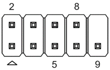
ED-SBC2300 series single-board includes 6 extended RS232 interfaces (JCOM1 ~ JCOM6) and standard JCOM pins with 2x5(9)-Pin 2.54mm pitch, which are used to extend RS232 interfaces. The pins of JCOM1 ~ JCOM6 are defined as follows:
| JCOM1 | Position Silkscreen | Pin ID | Pin Name |
|---|---|---|---|
 | J8 | 1 | NC |
| 2 | COM1_RS232_RX | ||
| 3 | COM1_RS232_TX | ||
| 4 | NC | ||
| 5 | GND | ||
| 6 | NC | ||
| 7 | COM1_RS232_RTS | ||
| 8 | COM1_RS232_CTS | ||
| 9 | NC |
| JCOM2 | Position Silkscreen | Pin ID | Pin Name |
|---|---|---|---|
| J9 | 1 | NC |
| 2 | COM2_RS232_RX | ||
| 3 | COM2_RS232_TX | ||
| 4 | NC | ||
| 5 | GND | ||
| 6 | NC | ||
| 7 | COM2_RS232_RTS | ||
| 8 | COM2_RS232_CTS | ||
| 9 | NC |
| JCOM3 | Position Silkscreen | Pin ID | Pin Name |
|---|---|---|---|
| J10 | 1 | NC |
| 2 | COM3_RS232_RX | ||
| 3 | COM3_RS232_TX | ||
| 4 | NC | ||
| 5 | GND | ||
| 6 | NC | ||
| 7 | COM3_RS232_RTS | ||
| 8 | COM3_RS232_CTS | ||
| 9 | NC |
| JCOM4 | Position Silkscreen | Pin ID | Pin Name |
|---|---|---|---|
| J11 | 1 | NC |
| 2 | COM4_RS232_RX | ||
| 3 | COM4_RS232_TX | ||
| 4 | NC | ||
| 5 | GND | ||
| 6 | NC | ||
| 7 | COM4_RS232_RTS | ||
| 8 | COM4_RS232_CTS | ||
| 9 | NC |
| JCOM5 | Position Silkscreen | Pin ID | Pin Name |
|---|---|---|---|
| J12 | 1 | NC |
| 2 | COM5_RS232_RX | ||
| 3 | COM5_RS232_TX | ||
| 4 | NC | ||
| 5 | GND | ||
| 6 | NC | ||
| 7 | COM5_RS232_RTS | ||
| 8 | COM5_RS232_CTS | ||
| 9 | NC |
| JCOM6 | Position Silkscreen | Pin ID | Pin Name |
|---|---|---|---|
| J13 | 1 | NC |
| 2 | COM6_RS232_RX | ||
| 3 | COM6_RS232_TX | ||
| 4 | NC | ||
| 5 | GND | ||
| 6 | NC | ||
| 7 | COM6_RS232_RTS | ||
| 8 | COM6_RS232_CTS | ||
| 9 | NC |
The CM4 pin names corresponding to the RS232 interfaces (COM1~COM2) are as follows:
| Signal | CM4 GPIO Name | CM4 Pin Out |
|---|---|---|
| COM1_RS232_RX | GPIO1 | CM4_UART_RXD2 |
| COM1_RS232_TX | GPIO0 | CM4_UART_TXD2 |
| COM2_RS232_RX | GPIO5 | CM4_UART_RXD3 |
| COM2_RS232_TX | GPIO4 | CM4_UART_TXD3 |
The SPI pin names corresponding to the RS232 interfaces (COM3~COM6) are as follows:
| Signal | SPI Pin Out |
|---|---|
| COM3_RS232_RX | SPI_UART_RXD1 |
| COM3_RS232_TX | SPI_UART_TXD1 |
| COM4_RS232_RX | SPI_UART_RXD2 |
| COM4_RS232_TX | SPI_UART_TXD2 |
| COM5_RS232_RX | SPI_UART_RXD3 |
| COM5_RS232_TX | SPI_UART_TXD3 |
| COM6_RS232_RX | SPI_UART_RXD4 |
| COM6_RS232_TX | SPI_UART_TXD4 |
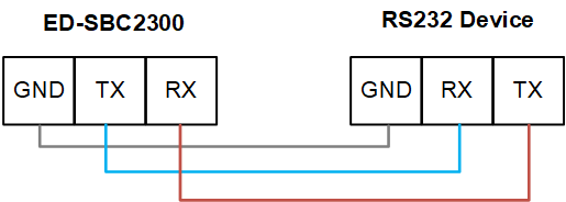
Connecting Cables
Schematic diagram of RS232 wires is as follows:
1.3.2.5 RS485
ED-SBC2300 series single-board includes two expanded RS485 interfaces (RS485_1 ~ RS485_2) and standard pins with 2x2-Pin 2.54mm pitch, which are used to expand RS485 ports. The pins of RS485-1 ~ RS485-2 are defined as follows:
| RS485_1 | Position Silkscreen | Pin ID | Pin Name |
|---|---|---|---|
 | J16 | 1 | RS485_1_B |
| 2 | RS485_1_A | ||
| 3 | GND | ||
| 4 | GND |
| RS485_2 | Position Silkscreen | Pin ID | Pin Name |
|---|---|---|---|
| J17 | 1 | RS485_2_B |
| 2 | RS485_2_A | ||
| 3 | GND | ||
| 4 | GND |
he pin names of the RS485 interface corresponding to CM4 are as follows:
| Signal | CM4 GPIO Name | CM4 Pin Out |
|---|---|---|
| RS485_1_A | GPIO12 | CM4_UART5_TXD |
| RS485_2_A | GPIO8 | CM4_UART4_TXD |
| RS485_1_B | GPIO13 | CM4_UART5_RXD |
| RS485_2_B | GPIO9 | CM4_UART4_RXD |
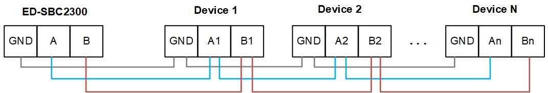
Connecting Cables
Schematic diagram of RS485 wires is as follows:
RS485 Terminal Resistor Configuration
ED-SBC2300 series single-board includes two RS485 interfaces. A jumper resistor of 120R is reserved between A and B of RS485 line, which can be enabled by inserting jumper cap. By default, the jumper cap is not connected, and the function of 120R termination resistor is invalid. The positions and pins of the two jumper resistors in PCBA are defined as follows.
TIP
J14 position corresponds to the terminal resistor of RS485_1(J16), and J15 position corresponds to the terminal resistor of RS485_2(J17).
| RS485_1 120R EN | Position Silkscreen | Pin ID | Pin Name |
|---|---|---|---|
 | J14 | 1 | RS485_1 120R_1 |
| 2 | RS485_1 120R_2 |
| RS485_2 120R EN | Position Silkscreen | Pin ID | Pin Name |
|---|---|---|---|
| J15 | 1 | RS485_2 120R_1 |
| 2 | RS485_2 120R_2 |
1.3.2.6 USB 2.0
The ED-SBC2300 series single-board includes 3 or 5 expanded USB 2.0 interfaces (FUSB1 ~ FUSB3) and 5-Pin or 2x5(9)-Pin 2.54mm pitch standard pin header for expanding USB 2.0 interfaces.
Different quantities correspond to different product models.
- ED-SBC2310:3 x USB 2.0 (including FUSB1 and FUSB3)
- ED-SBC2311:5 x USB 2.0 (including FUSB1、FUSB2 and FUSB3)
- ED-SBC2320:3 x USB 2.0 (including FUSB1 and FUSB3)
- ED-SBC2321:5 x USB 2.0 (including FUSB1、FUSB2 and FUSB3)
FUSB1 ~ FUSB3 pins are defined as follows:
| FUSB1 | Position Silkscreen | Pin ID | Pin Name |
|---|---|---|---|
| J19 | 1 | VBUS_A |
| 2 | VBUS_A | ||
| 3 | USB_DM1 | ||
| 4 | USB_DM2 | ||
| 5 | USB_DP1 | ||
| 6 | USB_DP2 | ||
| 7 | GND | ||
| 8 | GND | ||
| 9 | NC |
| FUSB2 | Position Silkscreen | Pin ID | Pin Name |
|---|---|---|---|
| J20 | 1 | VBUS_A |
| 2 | VBUS_A | ||
| 3 | USB_DM3 | ||
| 4 | USB_DM4 | ||
| 5 | USB_DP3 | ||
| 6 | USB_DP4 | ||
| 7 | GND | ||
| 8 | GND | ||
| 9 | NC |
| FUSB3 | Position Silkscreen | Pin ID | Pin Name |
|---|---|---|---|
 | J21 | 1 | VBUS_A |
| 2 | USB_DM5 | ||
| 3 | USB_DP5 | ||
| 4 | GND | ||
| 5 | NC |
1.3.2.7 4G Module
ED-SBC2300 series single-board includes a 4G module interface, mini PCIe connector, which supports connecting optional 4G modules to realize 4G functions. If the 4G module is selected, there is a Nano SIM card slot below the module for installing the SIM card for acquiring 4G signals.
1.3.2.8 mSATA
ED-SBC2300 series single-board include a mSATA interface, Mini PCIe connector for external mSATA hard drive.
1.3.2.9 Speaker
The ED-SBC2300 series single-board contains one extended Speaker output, 4-Pin 2.0mm pitch WTB connector, dual-channel stereo outputs for extended connection of two 4Ω 3W stereo speakers, with pinouts defined below:
 | Position Silkscreen | Pin ID | Pin Name |
|---|---|---|---|
| J22 | 1 | SPK_L_N | |
| 2 | SPK_L_P | ||
| 3 | SPK_R_N | ||
| 4 | SPK_R_P |
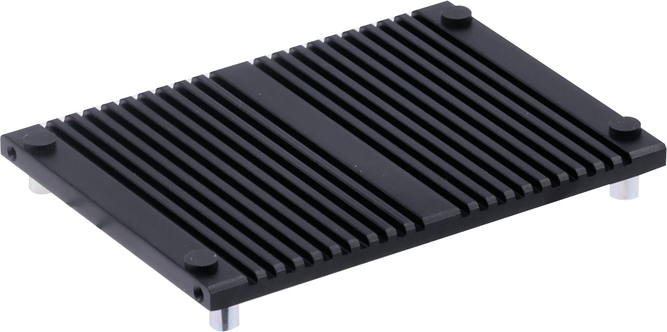
1.3.2.10 Passive Cooler (optional)
ED-SBC2300 series single-board have pre-drilled screw holes for mounting passive cooler and support optional passive cooler.
1.3.2.11 RPI_BOOT
The ED-SBC2300 series single-board contain one extended RPI_BOOT interface, 3-Pin 2.54mm pitch pin header with the following pin definitions:
 | Position Silkscreen | Pin ID | Pin Name |
|---|---|---|---|
| J44 | 1 | 3V3_EXT | |
| 2 | JMP_RPI_BOOT_EN_L | ||
| 3 | GND |
You can make the single board enter RPI BOOT mode by shorting Pin 2 and Pin 3, and then re-energizing.
1.3.2.12 Auto-boot after powering on
ED-SBC2300 series single-board includes one extended automatic power-on function interface, with 3-Pin 2.54mm pitch pin header, and the pins are defined as follows:
| Position Silkscreen | Pin ID | Pin Name |
|---|---|---|---|
| J40 | 1 | 3V3_STB | |
| 2 | JMP_AUTO_PWRON | ||
| 3 | GND |
1.3.2.13 Front Panel
ED-SBC2300 series single-board include one extended front panel interface, 2x5-Pin 2.54mm pitch pin header for expanding the connection of power button, reset button, HDD indicator and power indicator, the pin definition is as follows:
| Position Silkscreen | Pin ID | Pin Name |
|---|---|---|---|
| J41 | 1 | HDD_LED_P | |
| 2 | PWR_LED_P | ||
| 3 | HDD_LED_N | ||
| 4 | PWR_LED_N | ||
| 5 | RST_BTN_N | ||
| 6 | PWR_SW_N | ||
| 7 | RST_BTN_P | ||
| 8 | PWR_SW_P | ||
| 9 | NC |
1.3.2.14 GPIO Pin Header
ED-SBC2300 series single-board contain one GPIO Pin Header, 2x3-Pin 2.54mm pitch pin header, which is used to lead out the extended GPIO. The pins are defined as follows:
 | Position Silkscreen | Pin ID | Pin Name |
|---|---|---|---|
| J39 | 1 | 3V3_EXT | |
| 2 | GND | ||
| 3 | EXT_GPIO1 | ||
| 4 | EXT_GPIO3 | ||
| 5 | EXT_GPIO2 | ||
| 6 | EXT_GPIO4 |
1.3.2.15 LVDS Output & Configuration
The ED-SBC2300 series single-board include one extended LVDS output, 2x15-Pin 2.54mm pitch pin header, which can be extended to connect LVDS displays, and the resolution can support up to 1080p 60Hz. The specific pin definitions are as follows:
LVDS Output
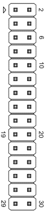 | Position Silkscreen | Pin ID | Pin Name | Pin ID | Pin Name |
|---|---|---|---|---|---|
| J45 | 1 | PANEL_VCC | 2 | PANEL_VCC | |
| 3 | PANEL_VCC | 4 | GND | ||
| 5 | GND | 6 | GND | ||
| 7 | DP_TXA0N | 8 | DP_TXA0P | ||
| 9 | DP_TXA1N | 10 | DP_TXA1P | ||
| 11 | DP_TXA2N | 12 | DP_TXA2P | ||
| 13 | GND | 14 | GND | ||
| 15 | DP_TXACN | 16 | DP_TXACP | ||
| 17 | DP_TXA3N | 18 | DP_TXA3P | ||
| 19 | DP_TXB0N | 20 | DP_TXB0P | ||
| 21 | DP_TXB1N | 22 | DP_TXB1P | ||
| 23 | DP_TXB2N | 24 | DP_TXB2P | ||
| 25 | GND | 26 | GND | ||
| 27 | DP_TXACN | 28 | DP_TXACP | ||
| 29 | DP_TXB3N | 30 | DP_TXB3P |
TIP
Only the ED-SBC2320 and ED-SBC2321 include this interface and configuration.
LVDS Screen Voltage Control
The ED-SBC2300 series single-board includes an extended LVDS screen voltage control interface with 3x2-Pin 2.54mm pitch pin header. It supports setting different power supply voltages by connecting different pins to meet the power supply requirements of various LVDS screens. The pin definitions and corresponding functions are as follows:
| Position Silkscreen | Pin ID | Pin Name |
|---|---|---|---|
| J32 | 1 | 3V3_EXT | |
| 2 | VCC_BL | ||
| 3 | 5V | ||
| 4 | VCC_BL | ||
| 5 | 12V | ||
| 6 | VCC_BL |
- Short Pin 1 and Pin 2:+3.3V
- Short Pin 3 and Pin 4:+5V
- Short Pin 5 and Pin 6:+12V
LVDS Output Resolution Adjustment
The ED-SBC2300 series single-board includes an extended LVDS output resolution adjustment interface with 3x4-Pin 2.0mm pitch pin header. It supports shorting pins to set different resolution screens. Pin definitions and corresponding functions are as follows:
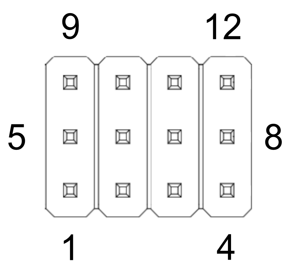 | Position Silkscreen | Pin ID | Pin Name |
|---|---|---|---|
| J35 | 1 | LVDS_IMPH_L | |
| 2 | LVDS_IMPH_L | ||
| 3 | LVDS_IMPH_L | ||
| 4 | LVDS_IMPH_L | ||
| 5 | LVDS_SET_0 | ||
| 6 | LVDS_SET_1 | ||
| 7 | LVDS_SET_2 | ||
| 8 | LVDS_SET_3 | ||
| 9 | LVDS_IMPH | ||
| 10 | LVDS_IMPH | ||
| 11 | LVDS_IMPH | ||
| 12 | LVDS_IMPH |
The corresponding resolution settings are as follows:
| State | SET_0(Pin 5) | SET_1(Pin 6) | SET_2(Pin 7) | SET_3(Pin 8) | Resolution |
|---|---|---|---|---|---|
| 0000 | Short to Pin 1 | Short to Pin 2 | Short to Pin 2 | Short to Pin 4 | S6 1024x600 |
| 0001 | Short to Pin 1 | Short to Pin 2 | Short to Pin 2 | Short to Pin 12 | S6 1024x768 |
| 0010 | Short to Pin 1 | Short to Pin 2 | Short to Pin 11 | Short to Pin 4 | S6 800x600 |
| 0011 | Short to Pin 1 | Short to Pin 2 | Short to Pin 11 | Short to Pin 12 | D6 1280x768 |
| 0100 | Short to Pin 1 | Short to Pin 10 | Short to Pin 2 | Short to Pin 4 | S6 1920x1080 |
| 0101 | Short to Pin 1 | Short to Pin 10 | Short to Pin 2 | Short to Pin 12 | S8 1366x768 |
| 0110 | Short to Pin 1 | Short to Pin 10 | Short to Pin 11 | Short to Pin 4 | S8 800x600 |
| 0111 | Short to Pin 1 | Short to Pin 10 | Short to Pin 11 | Short to Pin 12 | S8 1024x768 |
| 1000 | Short to Pin 9 | Short to Pin 2 | Short to Pin 2 | Short to Pin 4 | S8 1280x768 |
| 1001 | Short to Pin 9 | Short to Pin 2 | Short to Pin 2 | Short to Pin 12 | D8 1280x800 |
| 1010 | Short to Pin 9 | Short to Pin 2 | Short to Pin 11 | Short to Pin 4 | S8 1600x900 |
| 1011 | Short to Pin 9 | Short to Pin 2 | Short to Pin 11 | Short to Pin 12 | S6 1366x768 |
| 1100 | Short to Pin 9 | Short to Pin 10 | Short to Pin 2 | Short to Pin 4 | D8 1280x800 |
| 1101 | Short to Pin 9 | Short to Pin 10 | Short to Pin 2 | Short to Pin 12 | D8 1280x1024 |
| 1110 | Short to Pin 9 | Short to Pin 10 | Short to Pin 11 | Short to Pin 4 | D8 1440x900 |
| 1111 | Short to Pin 9 | Short to Pin 10 | Short to Pin 11 | Short to Pin 12 | D8 1920x1080 |
LVDS Screen Brightness Control
ED-SBC2300 series single-board includes an extended LVDS screen brightness control interface, 4-Pin 2.0mm WTB connector. The brightness of LVDS screen is controlled by connecting different pins. The pin definitions and corresponding functions are as follows:
 | Position Silkscreen | Pin ID | Pin Name |
|---|---|---|---|
| J34 | 1 | BL_UP_L_R | |
| 2 | GND | ||
| 3 | BL_DOWN_L_R | ||
| 4 | BL_EN_L_R |
- Connect Pin 1 and Pin 2: brightness+
- Connect Pin 2 and Pin 3:brightness-
- Connect Pin 2 and Pin 4:brightness switch
LVDS Screen Backlight Power
ED-SBC2300 series single-board includes one extended backlight power interface, 6-Pin 2.0mm WTB connector. The pins are defined as follows:
 | Position Silkscreen | Pin ID | Pin Name |
|---|---|---|---|
| J36 | 1 | 12V | |
| 2 | 12V | ||
| 3 | LVDS_BKL_EN | ||
| 4 | LVDS_BLK_PWM_R | ||
| 5 | GND | ||
| 6 | GND |
LVDS Screen Backlight Control
The ED-SBC2300 series single-board contains one extended backlight control interface, 6-Pin 2.0mm pitch WTB connector with the following pin definitions:
| Position Silkscreen | Pin ID | Pin Name |
|---|---|---|---|
| J33 | 1 | BL_LED_C | |
| 2 | BL_LED_C | ||
| 3 | BL_LED_A | ||
| 4 | BL_LED_A | ||
| 5 | BL_LED_C | ||
| 6 | BL_LED_C |