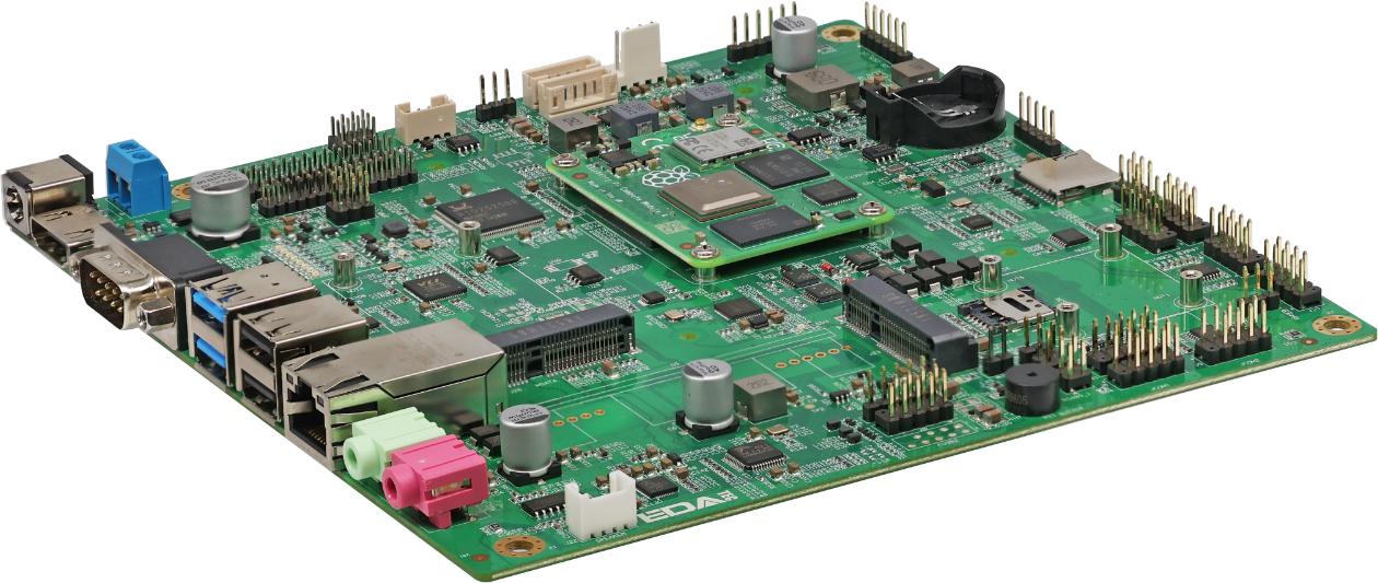
ED-SBC2300 Series
Mini-ITX Industrial Single Board Computer Based on Raspberry Pi CM4
|  |
Specifications
| System | |
|---|---|
| CPU | Broadcom BCM2711, quad core Cortex-A72 (ARM v8) 64-bit SoC @ 1.5GHz |
| VPU | H.265(HEVC), up to 4Kp60 decode H.264, up to 1080p60 decode, 1080p30 encode |
| GPU | OpenGL ES 3.1 & Vulkan 1.0 |
| Memory | Options for 1GB, 2GB, 4GB, 8GB LPDDR4-3200 SDRAM |
| Storage | Options for 8GB, 16GB, 32GB eMMC storage Micro SD card (user storage expansion) mSATA SSD (optional) |
| Software | |
|---|---|
| Operating System | Raspberry Pi OS (Desktop) 32-bit Raspberry Pi OS (Lite) 32-bit Raspberry Pi OS (Desktop) 64-bit Raspberry Pi OS (Lite) 64-bit |
| Rear I/O | |
|---|---|
| Power | 1 x DC IN, DC Jack connector (2-Pin 3.5mm pitch phoenix terminal is optional). It supports 9V~36V input. |
| HDMI | 1 x HDMI port, type A connector, which is compatibles with HDMI 2.0 standard and supports 4K 60Hz. |
| COM | 1 x RS232 port, DB9 male connector, using the 2, 3 and 5 pins, the corresponding signal is defined as RX/TX/GND. |
| USB 3.0 | 2 x USB 3.0 ports, type A connector, support up to 5Gbps. |
| USB2.0/1000M Ethernet | Choose one between 2 x USB 2.0 ports and 1 x 1000M Ethernet port.
|
| 1000M Ethernet | 1 x adaptive 10/100/1000M ethernet port, RJ45 connector. It can be used to access the network. |
| LINE OUT (optional) | 1 x Audio Output, 3.5mm audio jack connector(green), stereo audio output. Note: Only ED-SBC2320 and ED-SBC2321 contains this interface. |
| MIC IN (optional) | 1 x MIC Input, 3.5mm audio jack connector(red), which can connect to microphone. Note: Only ED-SBC2320 and ED-SBC2321 contains this interface. |
| SD Card Slot | 1 x Micro SD card slot, which is used to install SD card for storing user data. |
| SIM Card Slot | 1 x Micro SIM card slot, which is used to install SIM card for getting 4G signal. |
| Expansion I/O | |
|---|---|
| Power Supply | 1 x power port, 2-Pin 5mm pitch connector, reserving to provide power supply for motherboard. It supports 9V~36V input, the signal is defined as VIN+/GND. |
| Speaker (optional) | 1 x PA output, 4-Pin 2.0mm pitch WTB connector, dual channel stereo audio output. It can be extended to connect two 4Ω 3W stereo speakers, these pins are defined as R+/R-/L+/L-. Note: Only ED-SBC2320 and ED-SBC2321 contains this interface. |
| USB 2.0 | 3 x USB 2.0 ports or 5 x USB 2.0 ports, different numbers of USB 2.0 ports can be selected according to actual application.
|
| RS232 | 6 x RS232, 2x5(9)-Pin 2.54mm pitch Pin Header, which support to expand the RS232 ports. The single signal is defined as DCD/RXD/TXD/DTR/GND/DSR/RTS/CTS/R1. |
| RS485*1 | 2 x RS485, 2x2-Pin 2.54mm pitch Pin Header, which support to expand the RS485 port and the single signal is defined as A/B. A 120R jumper resistor is reserved between A and B of RS485 line. The jumper cap can be inserted to enable the jumper resistor. |
| 6-Pin GPIO | 1 x GPIO Pin Header, 2x3-Pin 2.54mm pitch Pin Header, which uses to lead out the expansion GPIO ports. User can customize the function according to actual application.The pins are defined as VCC/GND/4xGPIO. |
| mSATA*2 | 1 x mSATA port, Mini PCIe connector, which supports to connect mSATA SSD. |
| Front Panel (Buttons/Indicators) | 1 x Front Panel port, 2x5-Pin 2.54mm pitch Pin Header, reserving to connect power button, reset button, HDD indicator and power indicator. The pins are defined as HDD LED+/HDD LED-/PWR LED+/PWR LED-/RESET-SW/GND/GND/POWER-SW/GND/NC. |
| Auto-boot after powering on | 1 x Auto-boot port, 3-Pin 2.54mm pitch Pin Header, which can set whether to enable the auto-boot after powering on by choosing to connect different pins. The pins and functions are defined as follows:
|
| LVDS Display (optional) | 1 x LVDS Display Port, 2x15-Pin 2.54mm pitch Pin Header. It is reserved to connect LVDS display, and supports up to 1080p 60Hz. Note: Only ED-SBC2320 and ED-SBC2321 contains this interface. |
| Voltage Setting of LVDS Display (optional) | 1 x Voltage Setting port of LVDS display, 2x15-Pin 2.54mm pitch Pin Header. We can set different voltage by choosing to connect different pins, which meets the power supply requirements of various LVDS display. The pins and functions are defined as follows:
|
| Enabling Setting of LVDS Display (optional) | 1 x Enabling Setting port of LVDS display, 2x15-Pin 2.54mm pitch Pin Header. We can open or close the LVDS display by choosing to connect different pins. The pins and functions are defined as follows:
|
| Resolution Setting of LVDS Output (optional) | 1 x Resolution Setting port of LVDS Output, 3x4-Pin 2.0mm pitch Pin Header. We can select screens of different sizes and resolutions by setting the level of pins. Available screens: 12.1-inch (800x600), 15-inch (1024x768), 15.6-inch (1920x1080), 17-inch (1280x1024) and 21.5-inch (1920x1080). Note: Only ED-SBC2320 and ED-SBC2321 contains this interface. |
| Brightness Control of LVDS Display (optional) | 1 x Brightness Control port of LVDS display, 4-Pin 2.0mm pitch WTB connector. We can adjust brightness of LVDS display by choosing to connect different pins. The pins and functions are defined as follows:
|
| Backlight Power (optional) | 1 x Backlight Power port, 6-Pin 2.0mm pitch WTB connector, which provides 12V power supply, PWM enable and PWM adjustment for backlight of LVDS display. The pins are defined as +12V/+12V/GND/GND/LVDS_BKL_EN/LVDS_BKL_CTRL. Note: Only ED-SBC2320 and ED-SBC2321 contains this interface. |
| Backlight Control (optional) | 1 x Backlight Control port, 6-Pin 2.0mm pitch WTB connector, which integrates on-board backlight driver circuit, supports enabling and adjustment of backlight brightness. The pins are defined as Vdc-/Vdc-/Vdc+/Vdc+/Vdc-/Vdc-. Note: Only ED-SBC2320 and ED-SBC2321 contains this interface. |
| Expansion Performance | |
|---|---|
| EEPROM | Supports 4K byte storage and improves the ease of use of device. |
| Crypto Authentication | It can be matched to realize the required upper layer application and improves the security of device. |
| RTC | Ensure that the system clock is not affected by device power-off. Note: A CR2032 battery is provided by default in China. |
| Buzzer | A tip or an abnormity can be configurated according to actual application, which realizes the alarm function. |
| Electrical Characteristics | |
|---|---|
| Input Voltage | 9V ~ 36V DC |
| Power Consumption | 60W (Max) |
| Mechanical Characteristics | |
|---|---|
| Dimensions | 170mm x 170mm (W x D) |
| Weight | 100g |
| Wireless | |
|---|---|
| Wi-Fi/Bluetooth (optional) | 2.4GHz and 5GHz dual-band Wi-Fi
|
| 4G (optional) | Connect with various 4G LTE modules through the Mini PCIe interface.
|
| Environmental & Regulatory | |
|---|---|
| Operating Temperature | -25°C ~ 50°C |
| Storage Temperature | -25°C ~ 60°C |
| Ambient Humidity | 5% ~ 95% (non-condensing) |
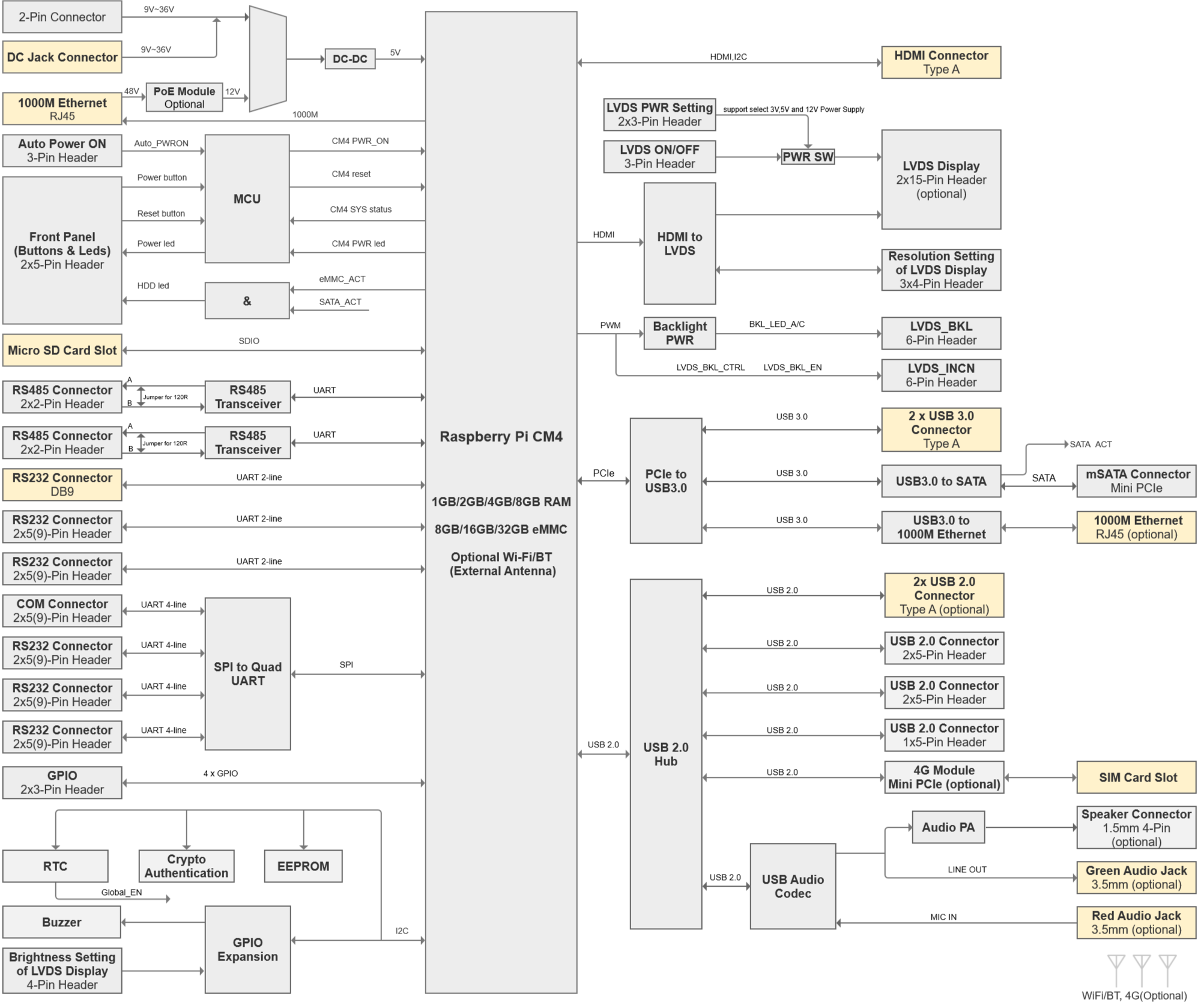
System Diagram
Known Issues
- *1: The RS485 function is not available at present. If you need to use RS485, we can manually modify it for you.
- *2: The read rate of some mSATA SSDs is slow.
Dimensions
Unit: mm

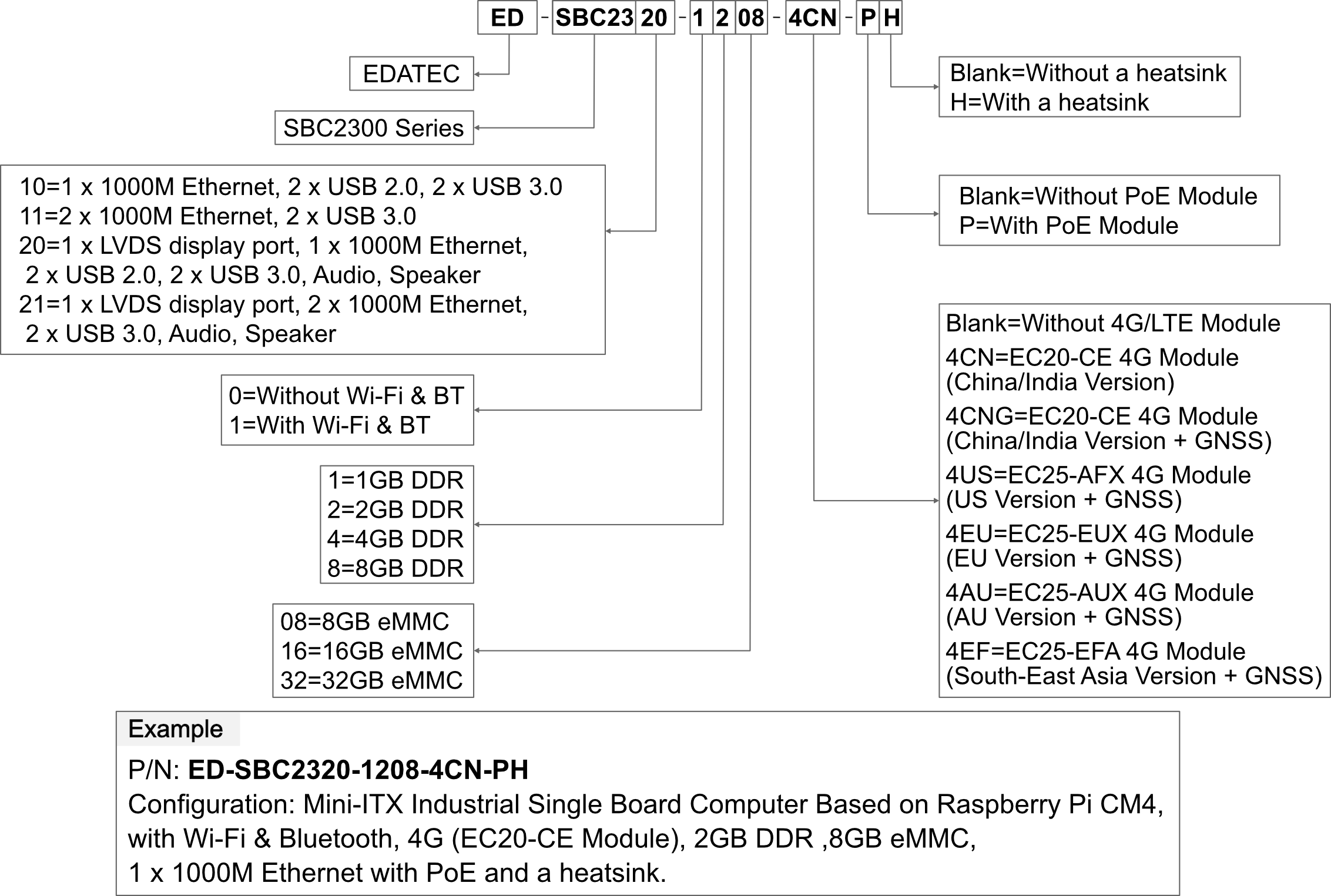
Ordering Code
Packing List
1 x ED-SBC2300 Motherboard