1 Hardware Manual
This chapter introduces the product overview, packing list, appearance, button, indicator and interface.
1.1 Overview
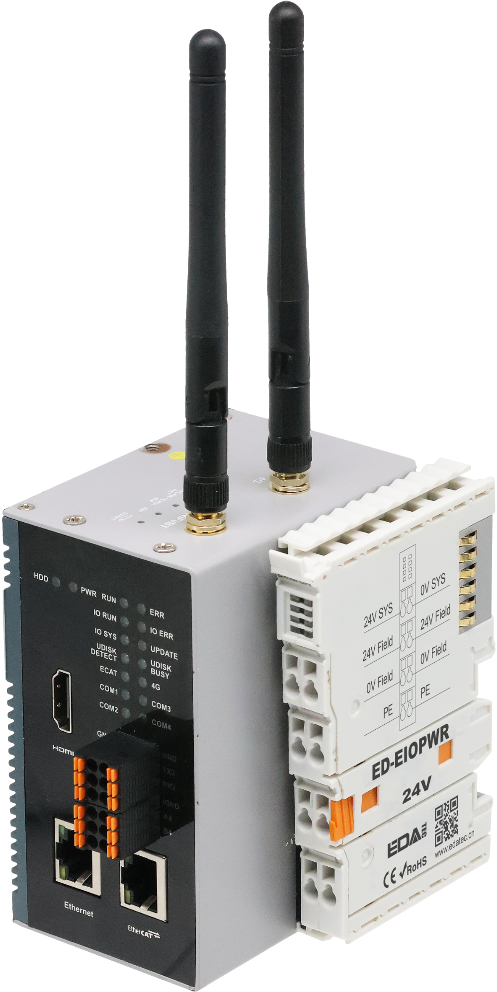
ED-PLC2010 is a programmable controller based on CODESYS. Depending on different application scenarios and user requirements, programmable logic systems with different specifications of RAM and eMMC can be selected.
- RAM can choose 1GB, 2GB, 4GB and 8GB
- eMMC can choose 8GB, 16GB and 32GB
WARNING
The ED-PLC2010 device comes pre-installed with a CODESYS license by default. Reinstalling the operating system will cause the CODESYS license to be lost. Please refrain from installing the operating system on your own.
ED-PLC2010 provides commonly used interfaces such as HDMI, USB, Ethernet, RS232 and RS485, and supports network access via Wi-Fi, Ethernet and 4G (optional); integrated RTC, Watch Dog, EEPROM, and encryption chip, which enhances the product's ease-of-use and reliability, and it's mainly applied to the industrial control field.
ED-PLC2010 supports the expansion of different types of I/O modules such as DI, DO, AI and AO, up to 32 I/O modules; integrated CODESYS Control runtime System, supports IEC 61131-3 programming standard and EtherCAT/Modbus TCP bus. Users can select the licenses of TargetVisu, WebVisu, Softmotion, CNC+Robotics, EtherCATMaster, Modbus TCP Master and OPC UA Server with different functions according to the actual needs.
1.2 Introduction to CODESYS Software
CODESYS is a powerful industrial automation programming software, which is an open control programming platform mainly used for programming and controlling programmable logic controllers (PLC), industrial (IPC) and other devices. Its full name is “Controller Development System”, which is widely used in the field of industrial automation, and is capable of realizing a variety of complex industrial control tasks, such as logic control, motion control, data processing, and so on.
CODESYS Features:
- CODESYS supports multiple programming languages, such as the five programming languages defined by the International Electrotechnical Commission (IEC) 61131 - 3 standard, including Ladder Diagram (LD), Function Block Diagram (FBD), Instruction List (IL), Structured Text (ST), and Sequential Function Chart (SFC).
- CODESYS has good cross-platform characteristics, it can run on many operating systems, such as Windows, Linux and so on. This cross-platform advantage allows users to choose the appropriate operating system environment for development according to actual needs.
- Provides a wealth of function libraries and function block libraries. These libraries cover a variety of functions in the field of industrial control, such as mathematical operations, communication protocol processing, motion control algorithms and so on. Users can directly call the functions and function blocks in these libraries, greatly reducing the development cycle.
- CODESYS supports a visual programming interface, which allows users to build program logic graphically. In terms of debugging, it provides powerful debugging tools, such as monitoring the values of variables online, executing the program in a single step, setting breakpoints, and so on. This enables developers to easily find and solve problems in their programs.
ED-PLC2010 supports CODESYS V3.5 SP19 and above.
1.3 Networking Application
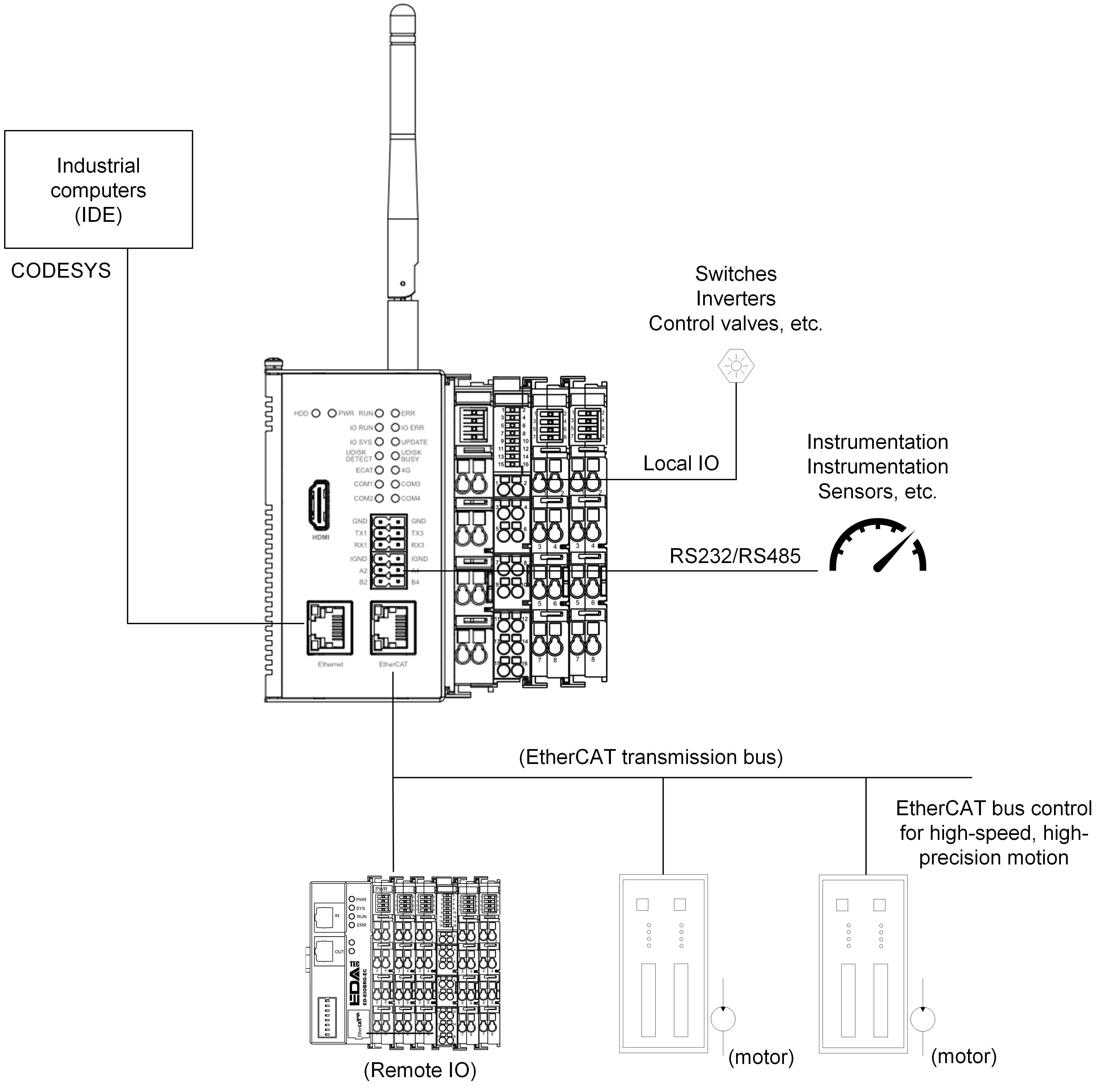
Equipped with EtherCAT, Ethernet and RS485, RS232 interfaces, ED-PLC2010 can realize multi-level network communication, which can meet the application requirements of multiple scenarios. Typical application topology is shown below:
1.4 Packing List
- 1x ED-PLC2010 Unit
- [option Wi-Fi/BT version] 1x 2.4GHz/5GHz Wi-Fi/BT Antenna
- [option 4G version] 1x 4G/LTE Antenna
1.5 Appearance
Introducing the functions and definitions of interfaces on each panel.
1.5.1 Front Panel
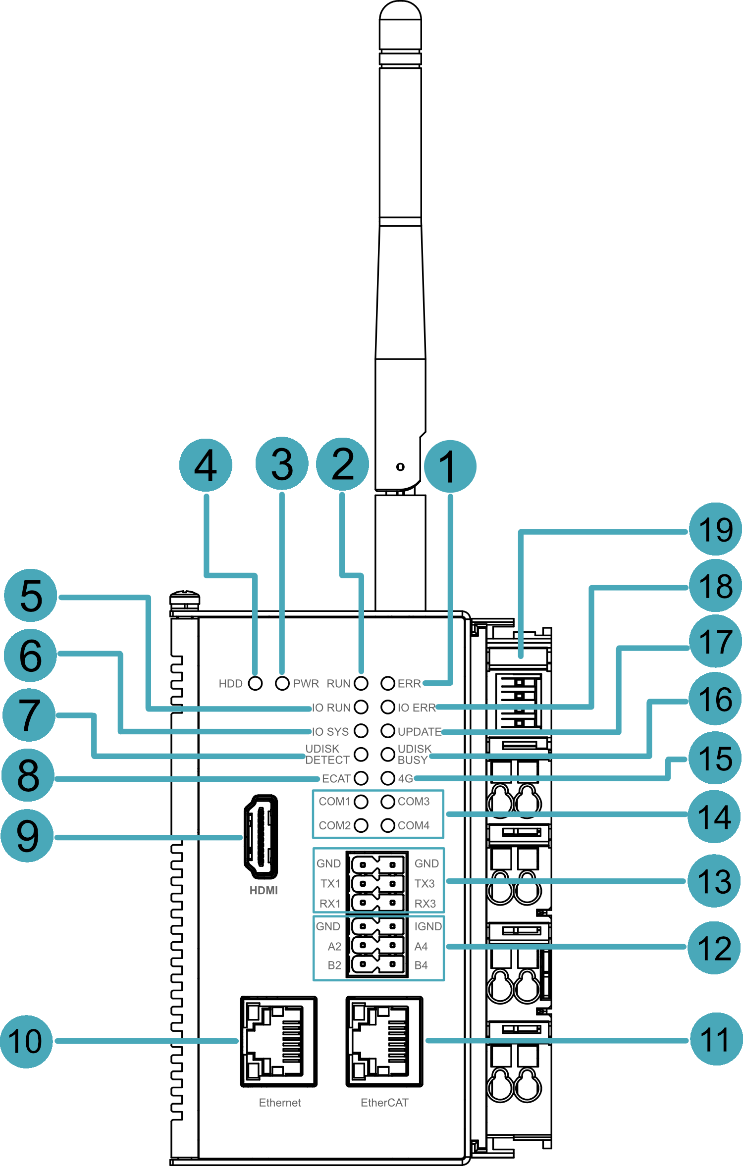
This section introduces functions and definitions of front panel.
| NO. | Function Definition |
|---|---|
| 1 | 1 x red ERR indicator, which is used to see if there are any system errors. |
| 2 | 1 x green RUN indicator, which is used to view the operational status of the device. |
| 3 | 1 x red Power indicator, which is used to see the status of the device powering up and powering down. |
| 4 | 1 x green HDD indicator, which is used to view the status of the device's eMMC read and write data. |
| 5 | 1 x green IO RUN indicator, which is used to view the operational status of the IO expansion module. |
| 6 | 1 x green IO SYS indicator, which is used to view the working status of the IO expansion module. |
| 7 | 1 x green UDISK DETECT indicator, which is used to check the detection status of the USB flash driver. |
| 8 | 1 x green ECAT indicator, which is used to check the connection status of the EtherCAT inputs |
| 9 | 1 x HDMI, type A connector, compatible with HDMI 2.1 standard, resolution support 4K 60Hz. |
| 10 | 1 x 10/100/1000M adaptive ethernet port, RJ45 connector, with led indicator. It can be used to access the network. |
| 11 | 1 x EtherCAT OUT, RJ45 connector for connecting an EtherCAT slave. |
| 12 | 2 x RS485, 6-Pin 3.5mm pitch Phoenix terminals with isolation protection, with ESD and surge protection, single signal defined as IGND/A/B. |
| 13 | 2 x RS232, 6-Pin 3.5mm pitch Phoenix terminals, with ESD and surge protection, single signal defined as GND/TX/RX. |
| 14 | 4 x Serial port indicators, green, for viewing the communication status of the serial port. |
| 15 | 1 x green 4G signal indicator, which is used to check the status of the 4G signal. |
| 16 | 1 x green UDISK BUSY indicator, which is used to check the mount status of a USB flash driver. |
| 17 | 1 x red UPDATE indicator, which is used to check the status of program updates. |
| 18 | 1 x red IO ERR indicator, which is used to see if there are any errors in the IO expansion module. |
| 19 | 1 x Power supply module for powering the ED-PLC2010 and extended I/O modules. |
1.5.2 Rear Panel
This section introduces interfaces and definitions of rear panel.

| NO. | Function Definition |
|---|---|
| 1 | 1 x Nano SIM slot, using to install a SIM card for acquiring 4G signals. |
| 2 | 1 x DIN-rail bracket, install ED-PLC2010 Unit on the DIN-rail through the bracket. |
| 3 | 1 x Micro-SD card slot, it supports the installation of SD card for storing user data. |
1.5.3 Side Panel
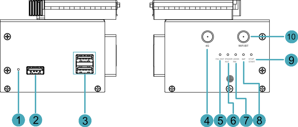
This section introduces functions and definitions of side panel.
| NO. | Function Definition |
|---|---|
| 1 | 1 x Reset button, hidden button, press the button to restart the device. |
| 2 | 1 x USB 2.0 port, type A connector, each channel supports up to 480Mbps. |
| 3 | 2 x USB 3.0 ports, type A connector, each channel supports up to 5Gbps. |
| 4 | 1 x 4G antenna port (optional), SMA connector, which can connect to 4G antenna. |
| 5 | 1 x FAC RST button for restoring factory settings. |
| 6 | 1 x IPADDR RST button for restoring the default IP address. |
| 7 | 1 x UDISK RM button for safe removal of USB storage devices. |
| 8 | 1 x IMP button for importing PLC programmes from a USB memory device or SD card. |
| 9 | 1 x STOP/START button to start/stop the PLC when it is running. |
| 10 | 1 x Wi-Fi/BT antenna port (optional), SMA connector, which can connect to Wi-Fi/BT antenna. |
1.6 Button
The ED-PLC2010 device contains 6 buttons, all of which are hidden and silk-screened on the case as ‘RESET’, ‘FAC RST’, ‘IPADDR RST’, ‘UDISK RM’, ‘IMP ’, ‘STOP START’.
| Button | Function Definition |
|---|---|
| RESET | Press the button to restart the device |
| FAC RST | Press and hold for more than 5 seconds to restore the device to its factory settings, short press is invalid. Possible operation purpose: Delete application, delete codesys login user name and password, restore default configuration file, while RUN or ERR indicator will be off and then on. |
| IPADDR RST | Press and hold more than 5 seconds to restore the device IP as default IP, short press is invalid. Default IP address: 192.168.0.100 for Ethernet port and 192.168.1.100 for EtherCAT port. |
| UDISK RM | Press and hold for more than 1 second to uninstall the USB flash driver, wait for the indicator light ‘UDISK BUSY’ to go out, it means uninstallation is successful; short press is invalid. |
| IMP | Press and hold for more than 1 second to start importing the application from the USB stick, wait for the indicator ‘UPDATE’ to flash, then it means the import is successful; short press is invalid. Application placement directory: USB drive root directory "Application" |
| STOP START | Press and hold for more than 1 second to start/stop the programme alternately, when the programme stops running, the indicator light ‘ERR’ is always on; short press is invalid. |
1.7 Indicator
Introducing the various statuses and meanings of indicators contained in ED-PLC2010 series device.
| Indicator | Status | Description |
|---|---|---|
| PWR | On | The device has been powered on. |
| Blink | Power supply of the device is abnormal, please stop the power supply immediately. | |
| Off | The device is not powered on. | |
| HDD | On | Device is reading and writing data via eMMC |
| Off | Device is not reading or writing data via eMMC | |
| RUN | On | Codesys runs fine |
| Off | Codesys does not run fine | |
| ERR | On | Press and hold the ‘STOP START’ button to stop the programme |
| Off | No program is imported or the imported program is running normally | |
| IO RUN | On | The user programme is running |
| Blink | I/O expansion modules have been recognized | |
| Off | I/O expansion module not recognized | |
| IO ERR | On | I/O expansion module running error |
| Off | I/O expansion module running normally | |
| IO SYS | On | I/O expansion module running abnormally |
| Blink | I/O expansion module running normally | |
| Off | I/O expansion module not running | |
| UPDATE | Blink | User programme updates |
| Off | User programme not updated | |
| UDISK DETECT | On | The device has detected the USB flash driver |
| Off | The device has not detected the USB flash driver | |
| UDISK BUSY | On | The USB flash driver is mounted to the device |
| Off | The USB flash driver is not mounted to the device | |
| ECAT | Slow Blink | EtherCAT communication is not connected |
| Quick Blink | EtherCAT communication is connected | 4G | Blink | 4G connection is normal |
| Off | 4G connection is abnormal | |
| Yellow indicator of Ethernet port | On | The data transmission is abnormal. |
| Blink | Data is being transmitted over the Ethernet port. | |
| Off | The Ethernet connection is not set up. | |
| Green indicator of Ethernet port | On | The Ethernet connection is in the normal state. |
| Blink | The Ethernet connection is abnormal. | |
| Off | The Ethernet connection is not set up. | |
| COM1~COM4 | On/Blink | Data is being transmitted. |
| Off | The device is not powered on or there is no data transmission. |
1.8 Interface
Introducing the definition and function of each interface in the product.
1.8.1 Card Slot
ED-PLC2010 series device includes an SD card slot and a Nano SIM card slot.
1.8.1.1 SD Card Slot
The silkscreen on the case of Micro SD card slot is“ ”,which is used to install SD card for storing user data.
1.8.1.2 SIM Card Slot (optional)
The silkscreen on the case of Nano SIM card slot is“ ”,which is used to install SIM card for obtaining 4G signals.
1.8.2 Power Supply Interface
The ED-PLC2010 device contains 1 power input module, including system power interface and Field power interface, with an input voltage of DC 24V (±20%) and an output system current of up to 2A.
Power module port definition:
| Pin ID | Pin Name | Pin ID | Pin Name |
|---|---|---|---|
| 1 | 24V SYS | 2 | 0V SYS |
| 3 | 24V Field | 4 | 24V Field |
| 5 | 0V Field | 6 | 0V Field |
| 7 | PE | 8 | PE |
1.8.3 RS485/RS232 Interface
ED-PLC2010 series devices include 2 RS485 interfaces and 2 RS232 interfaces, with RS485 single interface silk-screened as “IGND/A/B” and RS232 single interface silk-screened as “GND/TX/RX”.
Pin Definition
Terminal pins are defined as follows:
 | Pin ID | Pin Name |
|---|---|---|
| 1 | RS485-2_B | |
| 2 | RS485-4_B | |
| 3 | RS485-2_A | |
| 4 | RS485-4_A | |
| 5 | IGND | |
| 6 | IGND | |
| 7 | RS232-1_RX | |
| 8 | RS232-3_RX | |
| 9 | RS232-1_TX | |
| 10 | RS232-3_TX | |
| 11 | GND | |
| 12 | GND |
The pin names of CM4 corresponding to RS485/RS232 interface are as follows:
| Signal | CM4 GPIO Name | CM4 Pin Out |
|---|---|---|
| RS485-2_B | GPIO13 | UART5_RXD |
| RS485-4_B | GPIO9 | UART4_RXD |
| RS485-2_A | GPIO12 | UART5_TXD |
| RS485-4_A | GPIO8 | UART4_TXD |
| RS232-1_RX | GPIO5 | UART3_RXD |
| RS232-3_RX | GPIO1 | UART2_RXD |
| RS232-1_TX | GPIO4 | UART3_TXD |
| RS232-3_TX | GPIO0 | UART2_TXD |
Connecting Cables
Schematic diagram of RS485 wires is as follows:

Schematic diagram of RS232 wires is as follows:
1.8.4 1000M Ethernet Interface
The ED-PLC2010 device includes one adaptive 10/100/1000M Ethernet port, and the silkscreen is“Ethernet”. The connector is RJ45, which is used to access the Ethernet. The pins corresponding to the terminals are defined as follows:
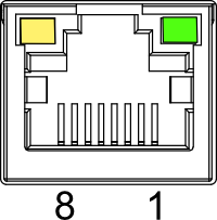 | Pin ID | Pin Name |
|---|---|---|
| 1 | TX1+ | |
| 2 | TX1- | |
| 3 | TX2+ | |
| 4 | TX2- | |
| 5 | TX3+ | |
| 6 | TX3- | |
| 7 | TX4+ | |
| 8 | TX4- |
1.8.5 EtherCAT Interface
ED-PLC2010 series device includes one EtherCAT port, the silkscreen is “EtherCAT”, The connector is RJ45, which is used to connect EtherCAT slaves.
1.8.6 HDMI Interface
ED-PLC2010 series device includes one HDMI port, the silkscreen is "HDMI". The connector is type A HDMI, which can connect to an HDMI display and supports up to 4Kp60.
1.8.7 USB 2.0 Interface
ED-PLC2010 series device includes one USB 2.0 port, the silkscreen is "". The connector is type A USB, which can connect to standard USB 2.0 peripherals and supports up to 480Mbps.
1.8.8 USB 3.0 Interface
ED-PLC2010 series device includes 2 USB 3.0 ports, the silkscreen is "". The connector is type A USB, which can connect to standard USB 3.0 peripherals and supports up to 5Gbps.
1.8.9 Antenna Interface (optional)
The ED-PLC2010 contains up to 2 SMA antenna ports, the silkscreens are "4G" and "WiFi/BT". They can be connected to the 4G antenna and Wi-Fi/BT antenna.。
1.8.10 Local Extended I/O Interface
ED-PLC2010 supports expansion of different types of I/O modules such as DI, DO, AI and AO, up to 32 I/O modules.
| Model | Description |
|---|---|
| ED-EIO8XP | 8-channel digital input module (PNP) |
| ED-EIO8XN | 8-channel digital input module (NPN) |
| ED-EIO16XP | 16-channel digital input module (PNP) |
| ED-EIO16XN | 16-channel digital input module (NPN) |
| ED-EIO8YP | 8-channel digital output module (PNP) |
| ED-EIO8YN | 8-channel digital output module (NPN) |
| ED-EIO16YP | 16-channel digital output module (PNP) |
| ED-EIO16YN | 16-channel digital output module (NPN) |
| ED-EIO4YR | 4-channel digital output module (Relay) |
| ED-EIO4ADV | 4-channel analog input module (voltage), -5~5V/0~10V/-10~10V, configurable |
| ED-EIO4ADA | 4-channel analog input module (current), 4-20mA/0-20mA, configurable |
| ED-EIO8ADA | 8-channel analog input module (current), 4-20mA/0-20mA, configurable |
| ED-EIO4AD | 4-channel analog input module (voltage/current mixed), -5~5V/0~10V/-10~10V/4-20mA/0-20mA, configurable |
| ED-EIO4DAV | 4-channel analog output module (voltage), -5~5V/0~10V/-10~10V, configurable |
| ED-EIO4DAA | 4-channel analog output module (current), 4-20mA/0-20mA, configurable |
| ED-EIO4RTD | 4-channel RTD Module |
| ED-EIO4TC | 4-channel TC Module |
| ED-EIO2HCD | 2-channel High Speed Counter Module |
| ED-EIOPWR | Power Expansion Supply Module |
| ED-EIOTERM | Bus End Cover |
