4 CODESYS Programming
This chapter details the specific operations involved in using CODESYS.
WARNING
The ED-PAC3630 device comes pre-installed with a valid CODESYS license by default. Reinstalling the operating system will invalidate the CODESYS license. Do not attempt to install the OS on your own.
4.1 CODESYS Software Download and Installation
TIP
The installed CODESYS IDE version must be 3.5.19 or higher, and the PC operating system must be Windows 10 or Windows 11 (64-bit recommended).
- Download the installation package from the official CODESYS website. The download URL is https://store.codesys.com/de/.
TIP
When downloading from the CODESYS official website for the first time, you must first register and log in to your account.
Right-click the downloaded installer and select "Run as administrator" from the context menu.
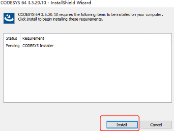
Click "Install" in the opened installation interface, and keep the default configuration during the installation process.
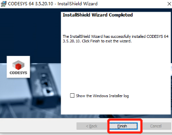
- After the installation is complete, click "Finish" to close the installation interface.
4.2 Obtaining and Installing Device Description File
Before connecting to the device via CODESYS, you need to download and install the device description file first.
4.2.1 Obtaining Device Description File
TIP
The default IP addresses for the device are:
- 100M Ethernet port: 192.168.1.100
- 1000M Ethernet port (EtherCAT port): 192.168.0.100 If you need to modify these settings, refer to Configuring Ethernet IP.
Preparation:
- A CODESYS-authorized ED-PAC3630 is available.
- A functional Ethernet cable is available.
- A Windows PC is prepared, with its IP address configured to the same subnet as the device. For example, if the device’s IP (1000M Ethernet port) is
192.168.0.100, set the PC’s IP to192.168.0.99.
Steps:
Connect the device's 1000M Ethernet port to the PC via an Ethernet cable, then power on the device.
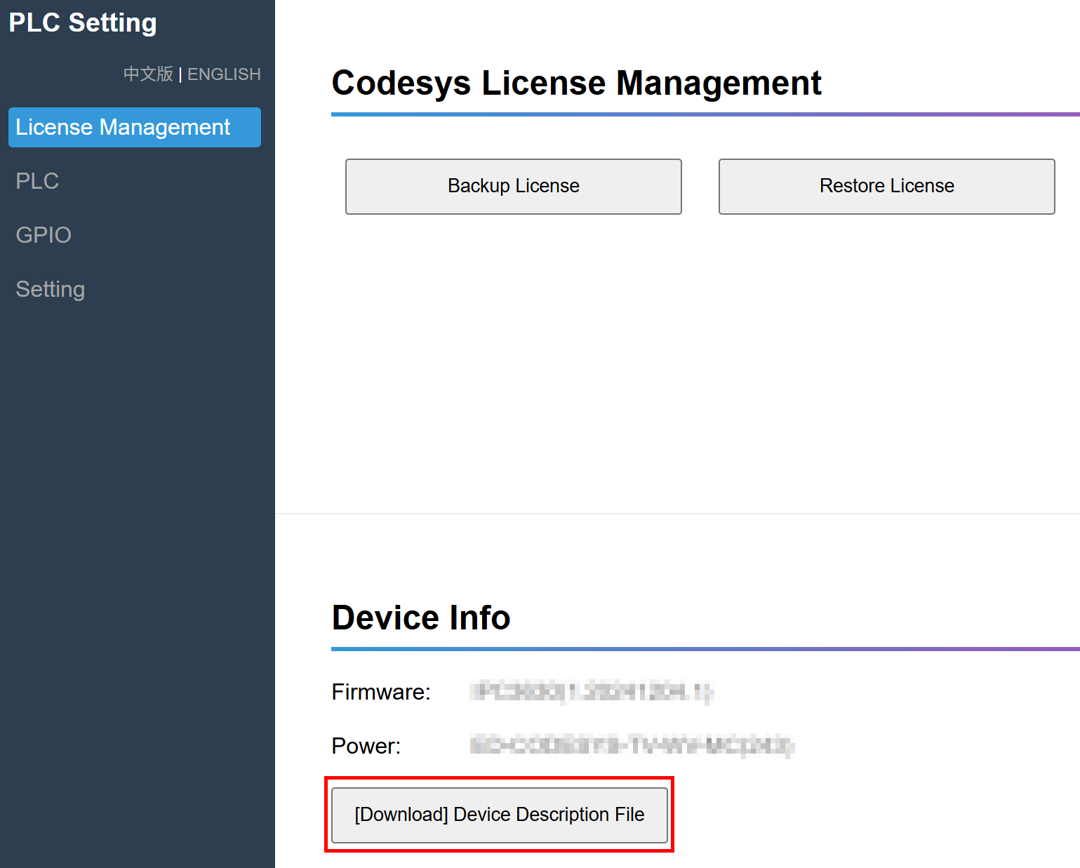
Enter
http://192.168.0.100:8100in the PC’s web browser to access the "PLC Setting" interface.In the "Device Info" section, click the "[Download] Device Description File" button to download the corresponding ".xml" format device description file.
TIP
The device files are available for download within the documentation. Different CODESYS licenses correspond to different device files. For specific descriptions and download paths, please refer to Device File and Function Correspondence Table.
4.2.2 Installing Device Description File
Preparation:
- A PC installed with CODESYS software version V3.5 SP19 (64-bit).
- An ED-PAC3630 device with a valid CODESYS license and its corresponding device description file.
- Connect both the PC and ED-PAC3630 to the network, ensuring their IP addresses are within the same subnet.
Steps:
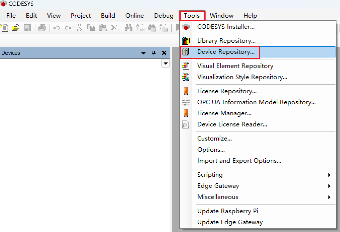
- Double-click the CODESYS icon on the PC desktop to open the CODESYS software. From the menu bar, select “Tools” → “Device Repository”.
- In the opened "Device Repository" pane, click "Install".
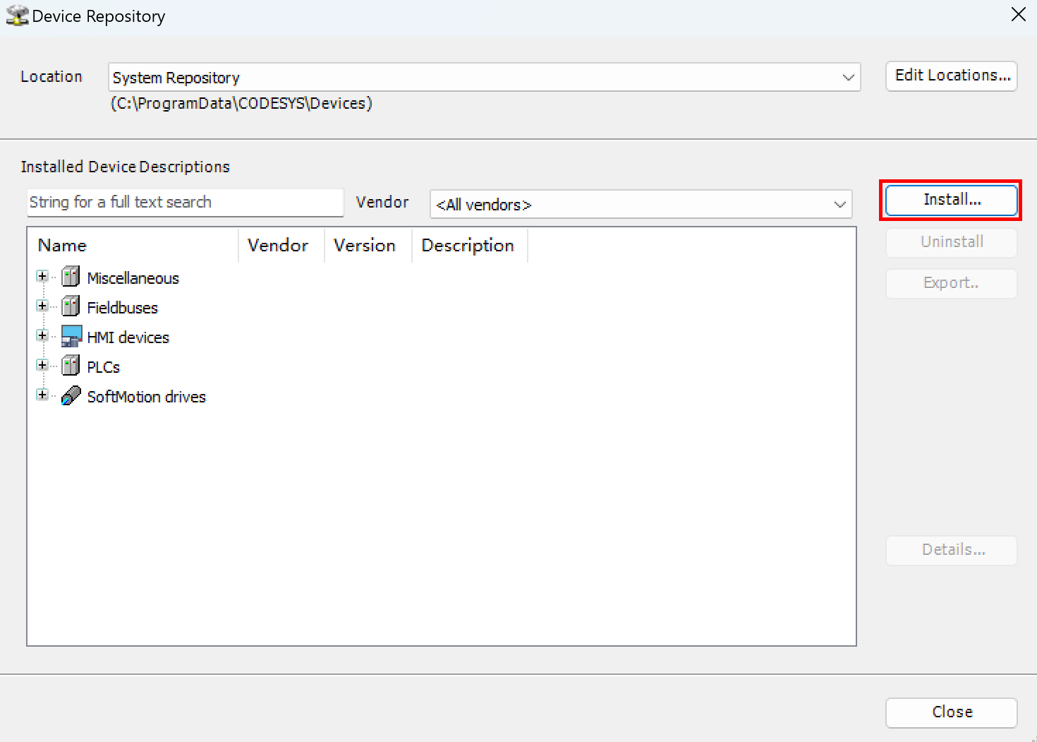
In the pop-up "Install Device Description" pane, select the device description file to be installed and click "Open" to proceed with the installation.
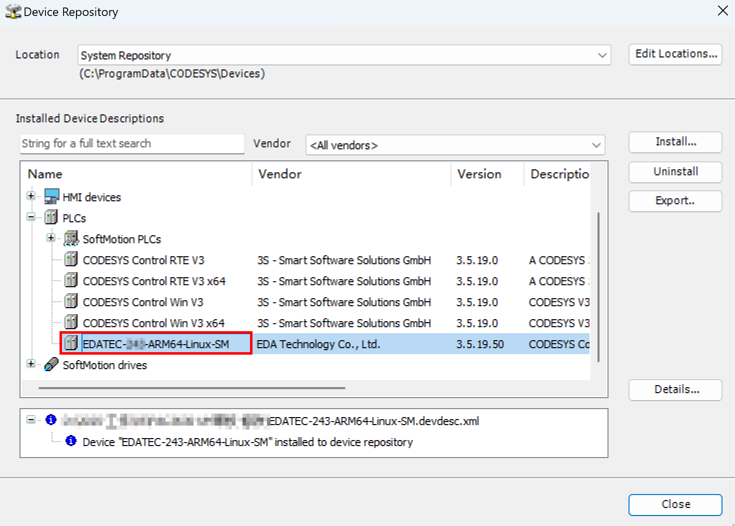
After successful installation, you can verify in the "Device Repository" that the device description file have been added successfully.
4.2.3 Installing GPIO Description File
TIP
If the you need to control DI, DO, or other GPIOs on the device via CODESYS, it is recommended to install the GPIO description file.
Preparation:
- A PC installed with CODESYS software version V3.5 SP19 (64-bit).
- A CODESYS-authorized ED-PAC3630 device available.
- GPIO description file obtained, with the download link: GPIO Description File.
- Connect both the PC and ED-PAC3630 to the network, ensuring their IP addresses are within the same subnet.
Steps:
- Double-click the CODESYS icon on the PC desktop to open the CODESYS software. From the menu bar, select “Tools” → “Device Repository”.
- In the opened "Device Repository" pane, click "Install".
In the pop-up "Install Device Description" pane, select the GPIO description file to be installed and click "Open" to proceed with the installation.
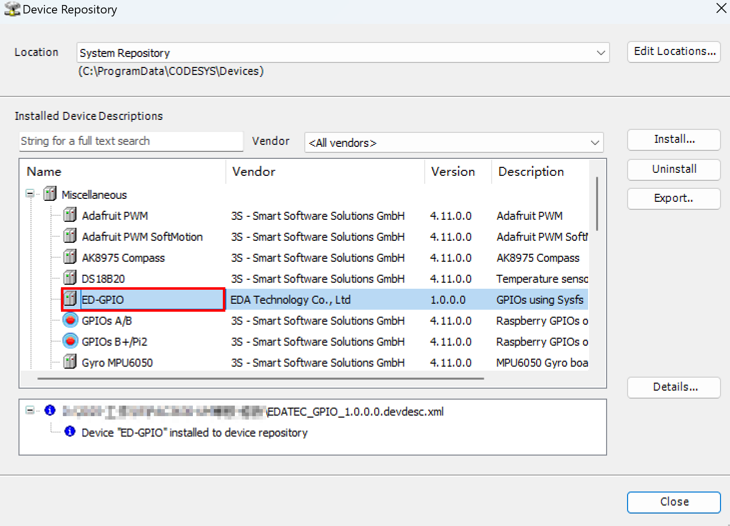
After successful installation, you can verify in the "Device Repository" that the GPIO description file have been added successfully.
4.2.4 Installing Remote I/O Device Description File
Preparation:
- A PC installed with CODESYS software version V3.5 SP19 (64-bit).
- A CODESYS-authorized ED-PAC3630 device available.
- Remote I/O device description file obtained, with the download link: Remote I/O Description File.
- Connect both the PC and ED-PAC3630 to the network, ensuring their IP addresses are within the same subnet.
Steps:
- Double-click the CODESYS icon on the PC desktop to open the CODESYS software. From the menu bar, select “Tools” → “Device Repository”.
- In the opened "Device Repository" pane, click "Install".
In the pop-up "Install Device Description" pane, select the I/O device decirption file to be installed and click "Open" to proceed with the installation.
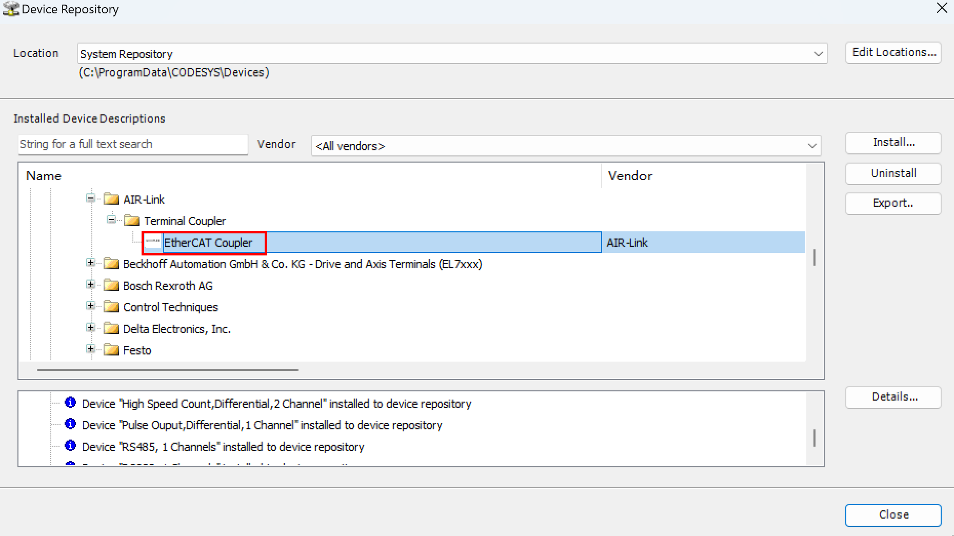
After successful installation, you can verify in the "Device Repository" that the I/O device description file have been added successfully.
4.3 Hardware Configuration
Preparation:
- A PC with CODESYS software version V3.5 SP19 (64-bit) installed, configured to operate on the same subnet as the device.
- Device description file, remote I/O device description file, and GPIO description file have been installed.
- The remote I/O modules have been connected to the ED-PAC3630's EtherCAT port (Gigabit Ethernet port) via network cable. Configure the IP addresses of the PC, ED-PAC3630, and remote I/O within the same subnet.
4.3.1 Create a New Project and Connect to the Device
Steps:
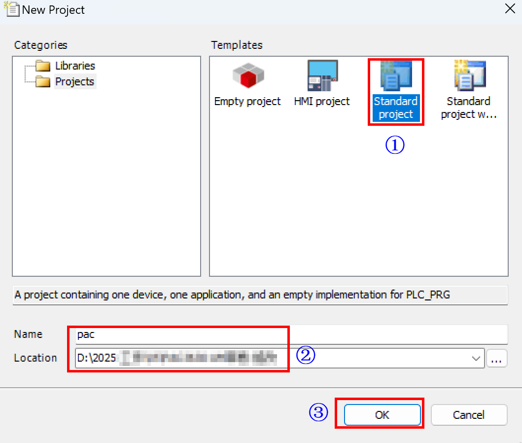
- Power on the ED-PAC3630 and the remote I/O modules. Open the CODESYS software on the PC, select "File" → "New Project" in the menu bar to open the "New Project" pane, and create a standard project.
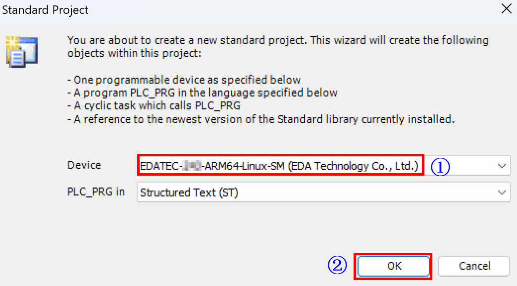
- Select the installed device description file and click "OK".
- Double-click the device, select "Scan Network" on the right, then choose the detected device from the scan results, and click "OK" to confirm.
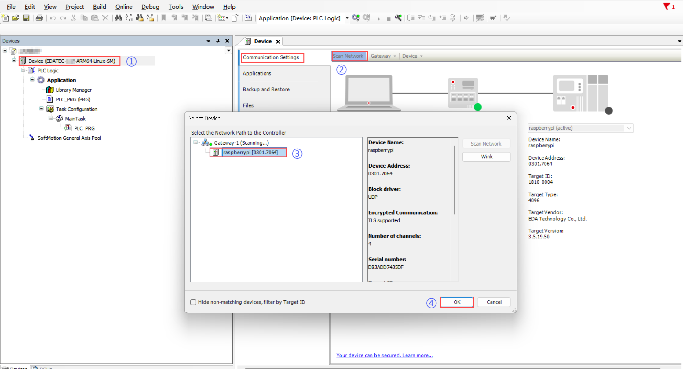
TIP
- If the device cannot be detected during scanning, manually enter the IP address in the target device settings to connect.
- If a device login prompt appears, log in with your credentials (username and password) or follow the instructions to register a new account.
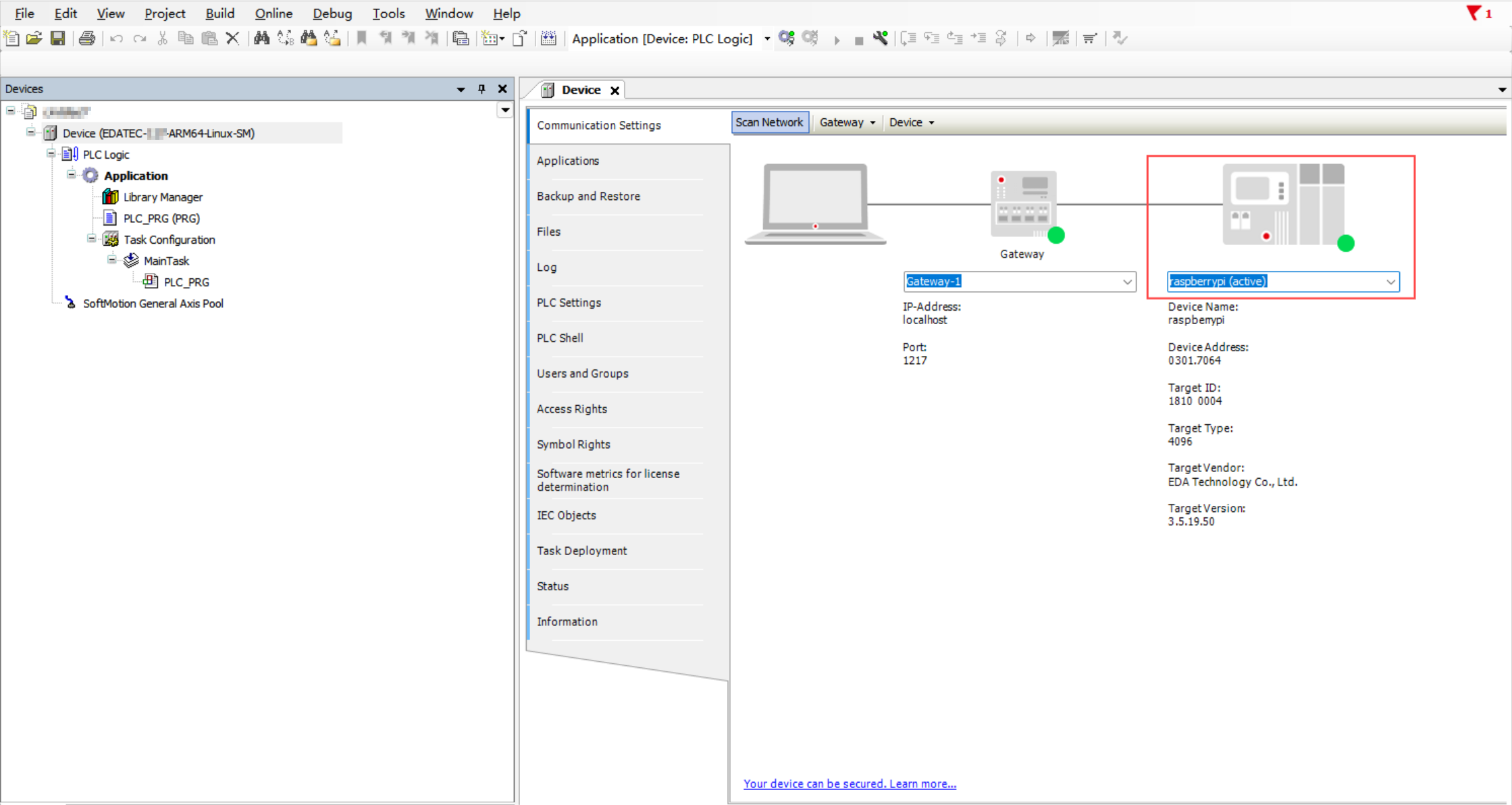
- As shown in the figure below, this indicates the device is successfully connected.
4.3.2 Adding Remote I/O Modules
Steps:
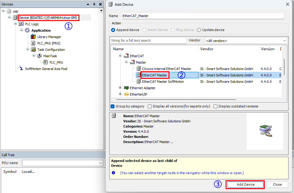
- Right-click “Device” and select “Add Device” in the menu to add the EtherCAT Master.
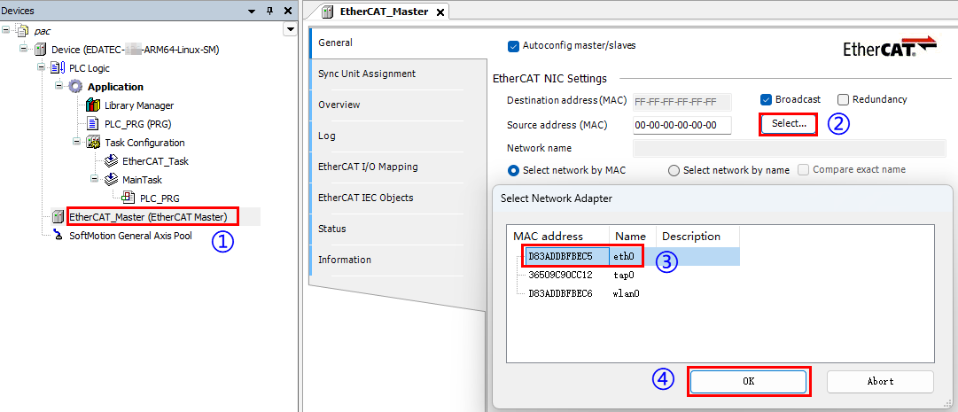
- Double-click on the EtherCAT Master device to set the source address (Select the EtherCAT port, which corresponds to the device's eth0 port).
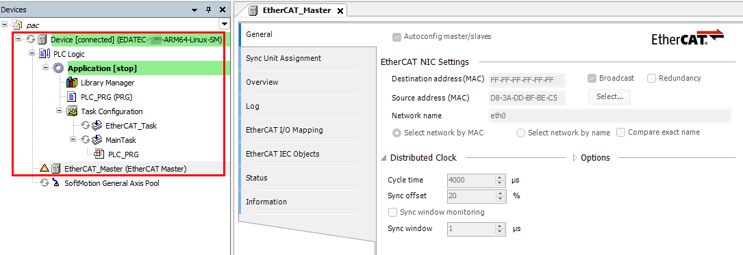
- Click the
 button to log in to the device. A successful login is shown in the figure below.
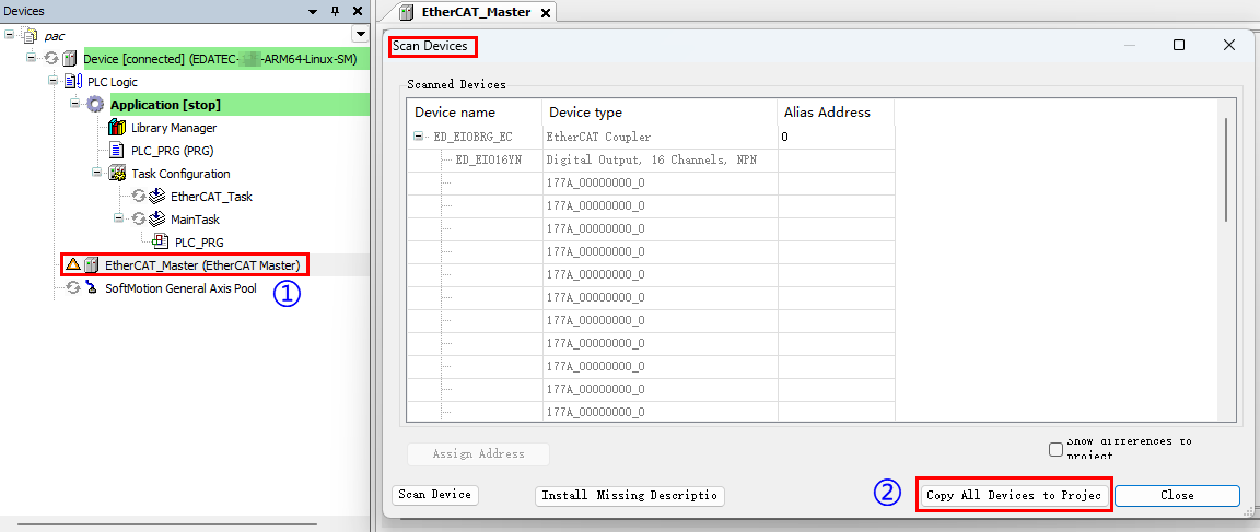
- Click on the EtherCAT Master device, select “Scan for Devices” in the right-click menu, and copy all devices to the project after scanning is completed.
Click the
 button to log out of the device.
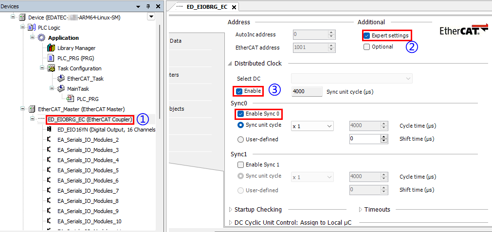
Double-click the slave device, configure the relevant parameters in the right-hand interface, enable "Expert settings", select "Enable" under Select DC section, and select "Enable Sync0".
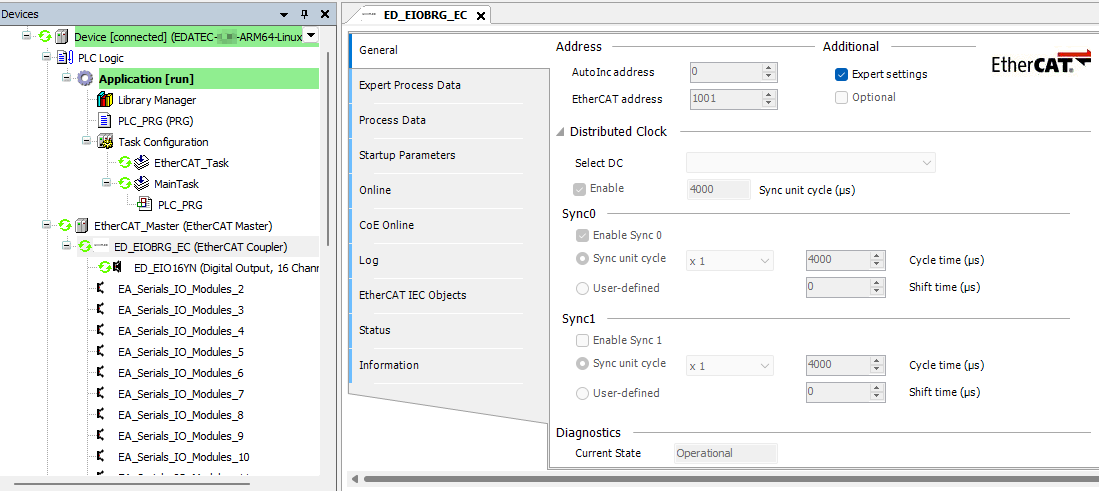
- Click the button to download the program to the device, then click the
 button to run it. As shown in the figure below, this indicates a successful operation.
4.3.3 Adding GPIO Module
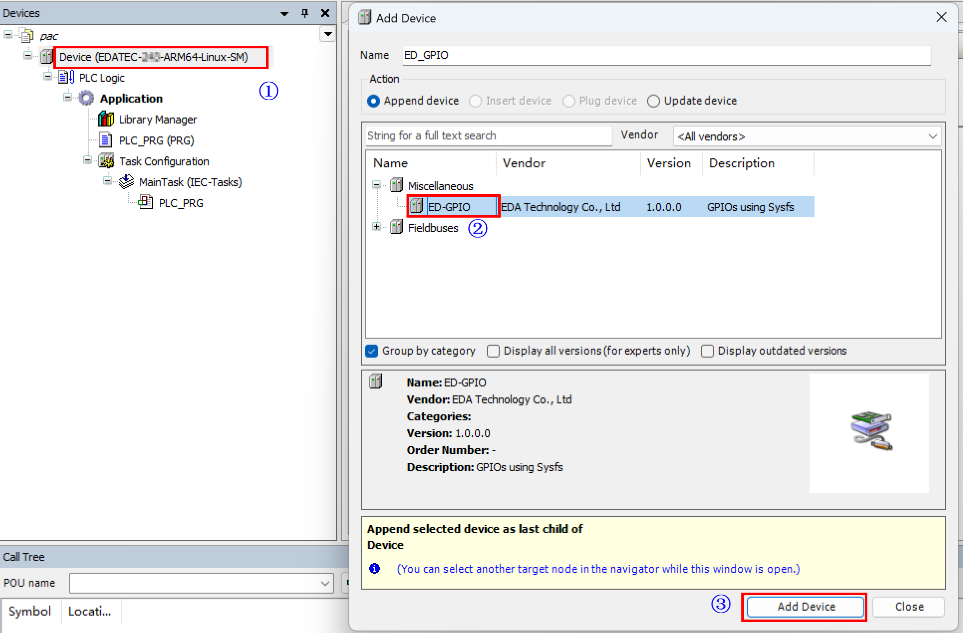
- Right-click “Device” and select “Add Device” in the menu to add ED-GPIO.
- Right-click "ED_GPIO", select "Add Device" from the menu, and choose the device to be added.
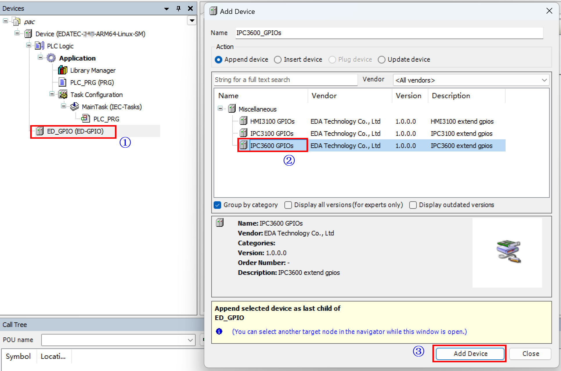
The appearance of the corresponding device under the ED_GPIO device directory indicates a successful addition.
Double-click the GPIO device to view and control the GPIO in the right-hand interface.
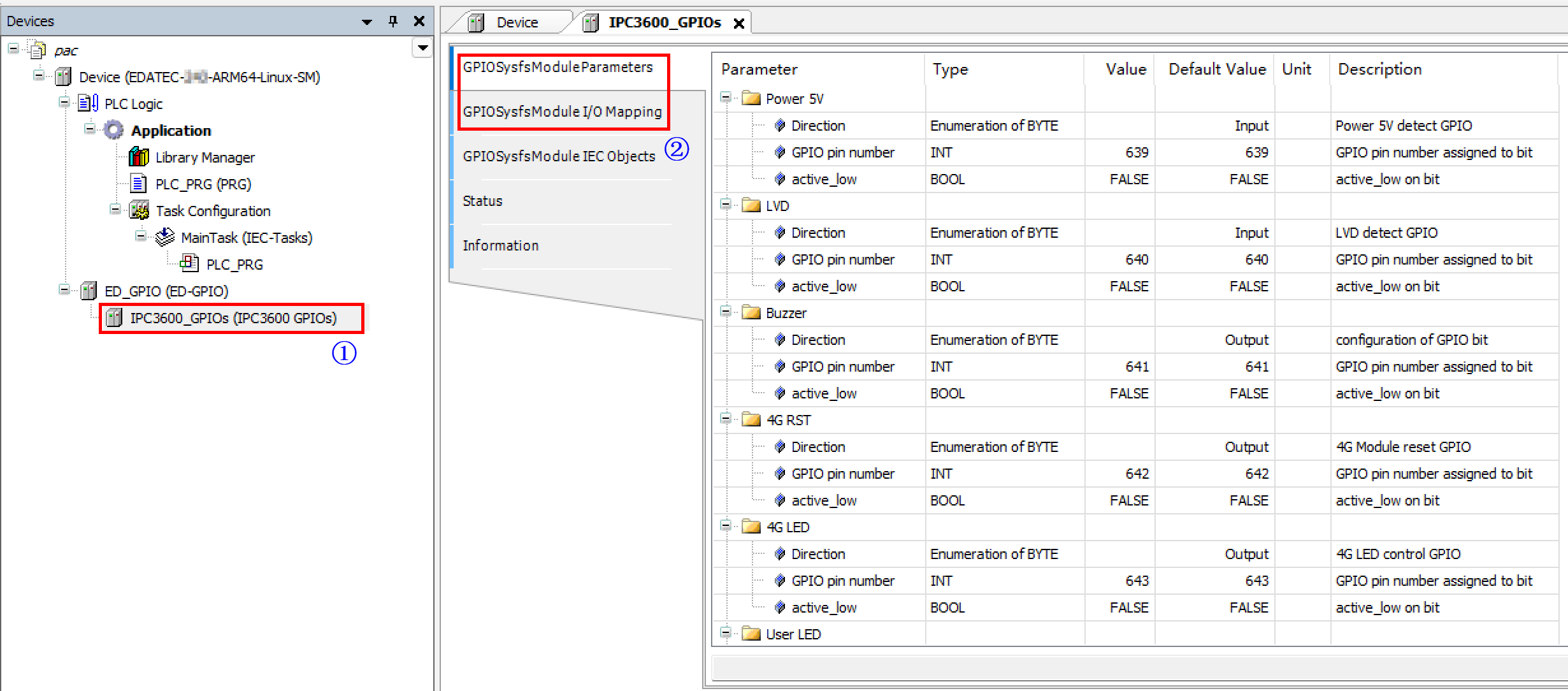
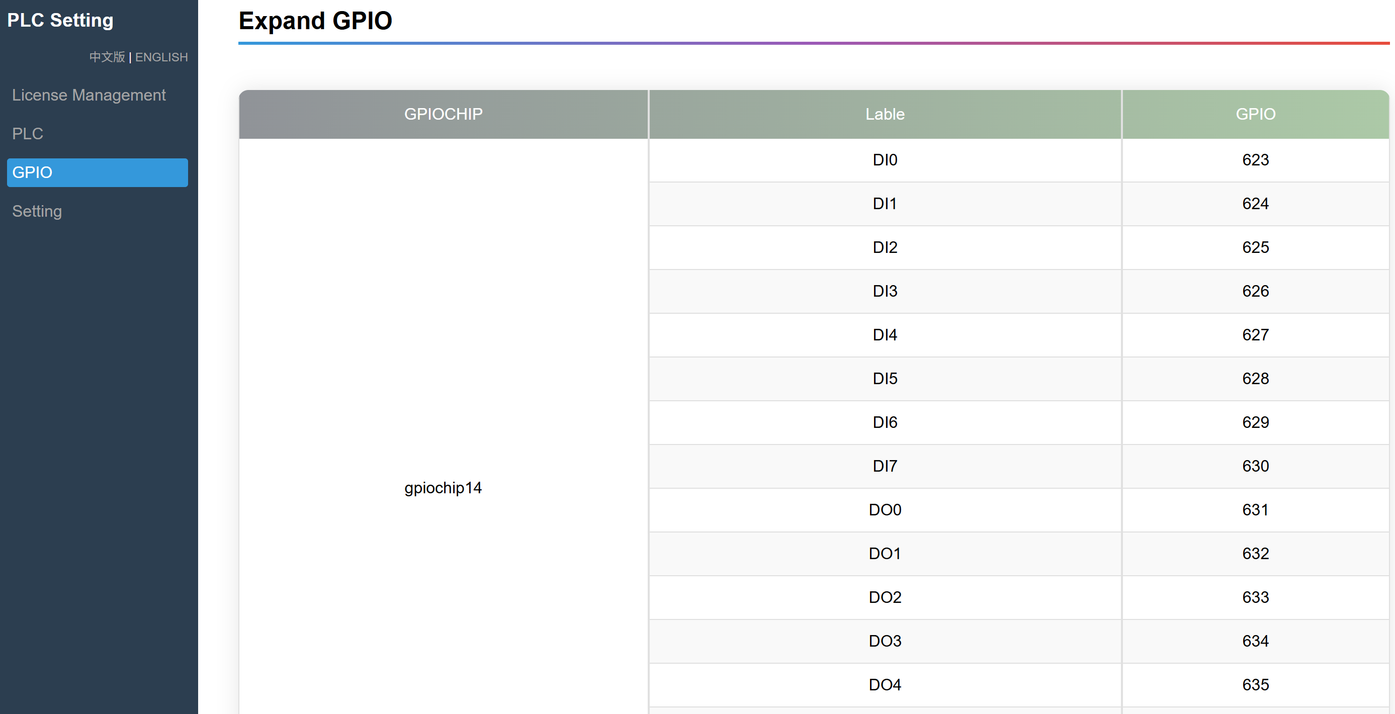
TIP
The GPIO numbering may vary between devices. It is recommended to access the "PLC Setting" interface (http://192.168.0.100:8100) to view the device-specific GPIO numbering.
4.4 Programming
The following example demonstrates practical programming using a specific coding scenario.
4.4.1 Programming Process
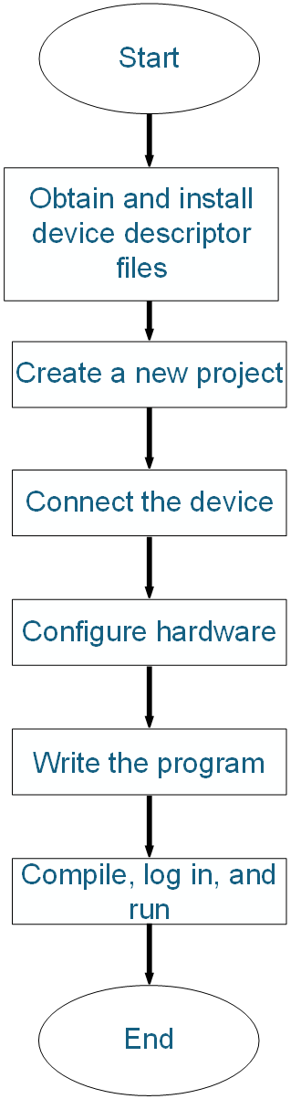
4.4.2 Programming Example
Complete the development and debugging of a program for a timed blinking LED using a PNP-type 8-channel digital output (DO) module.
Preparation:
- A standard project has been created.
- Hardware configuration has been completed.
- A 24V compact LED lamp has been connected to the first output port of the remote DO (Digital Output) module.
Steps:
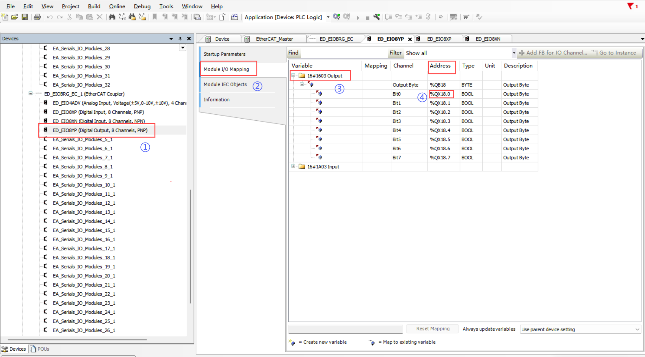
- Double-click the DO module, select "Module I/O Mapping" → "Output" in the right-hand interface, and view the addresses of all output ports. As illustrated below, the first output port’s address is
%QX18.0.
- Click "PLC_PLG" to open the programming interface, where the upper section is the variable declaration area and the lower section is the main program editing area.
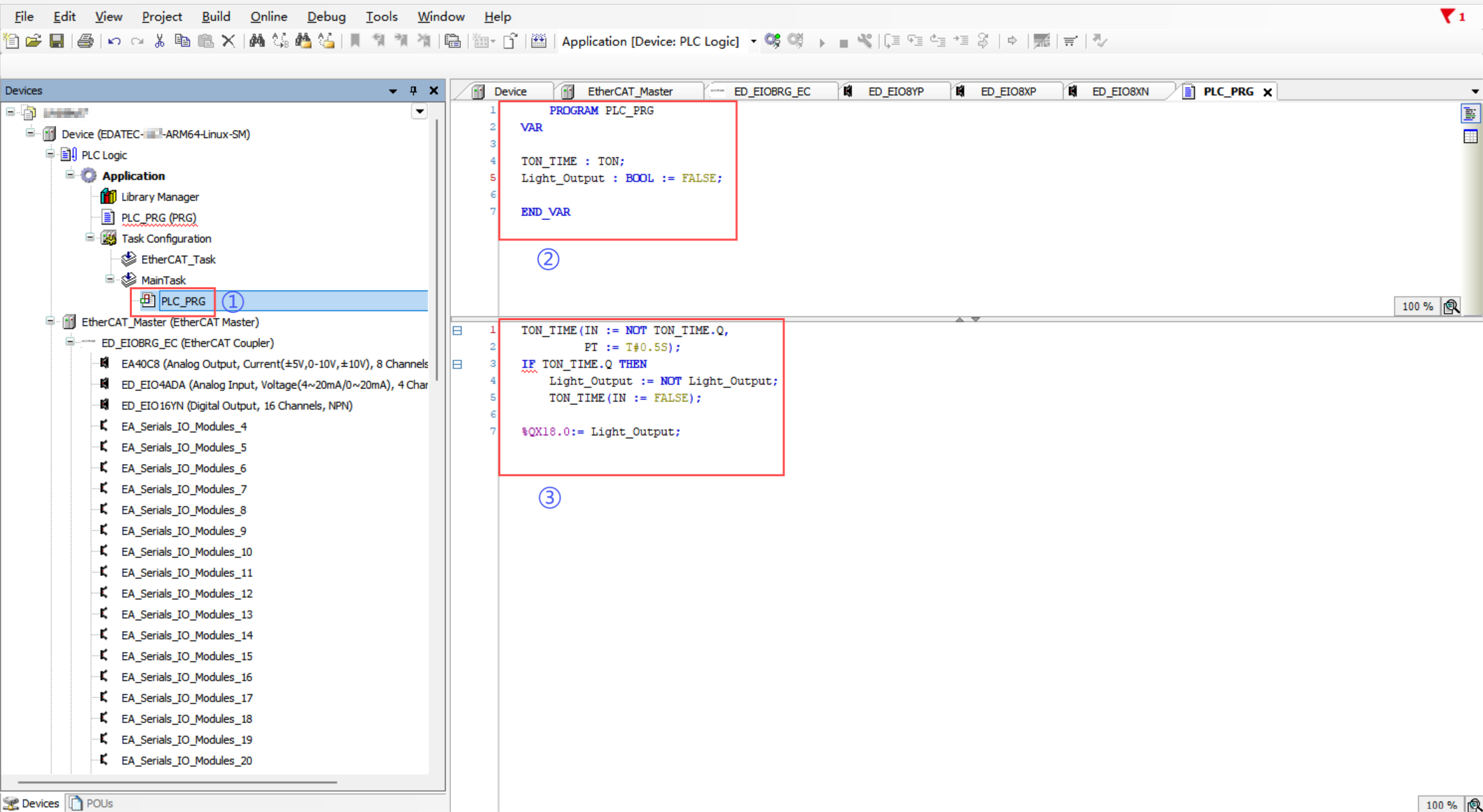
- Write the program code as follows:
    PROGRAM PLC_PRG
VAR

TON_TIME : TON;
Light_Output : BOOL := FALSE;

END_VAR
TON_TIME(IN := NOT TON_TIME.Q,
         PT := T#0.5S);
IF TON_TIME.Q THEN
    Light_Output := NOT Light_Output;
    TON_TIME(IN := FALSE);
END_IF

%QX18.0:= Light_Output;
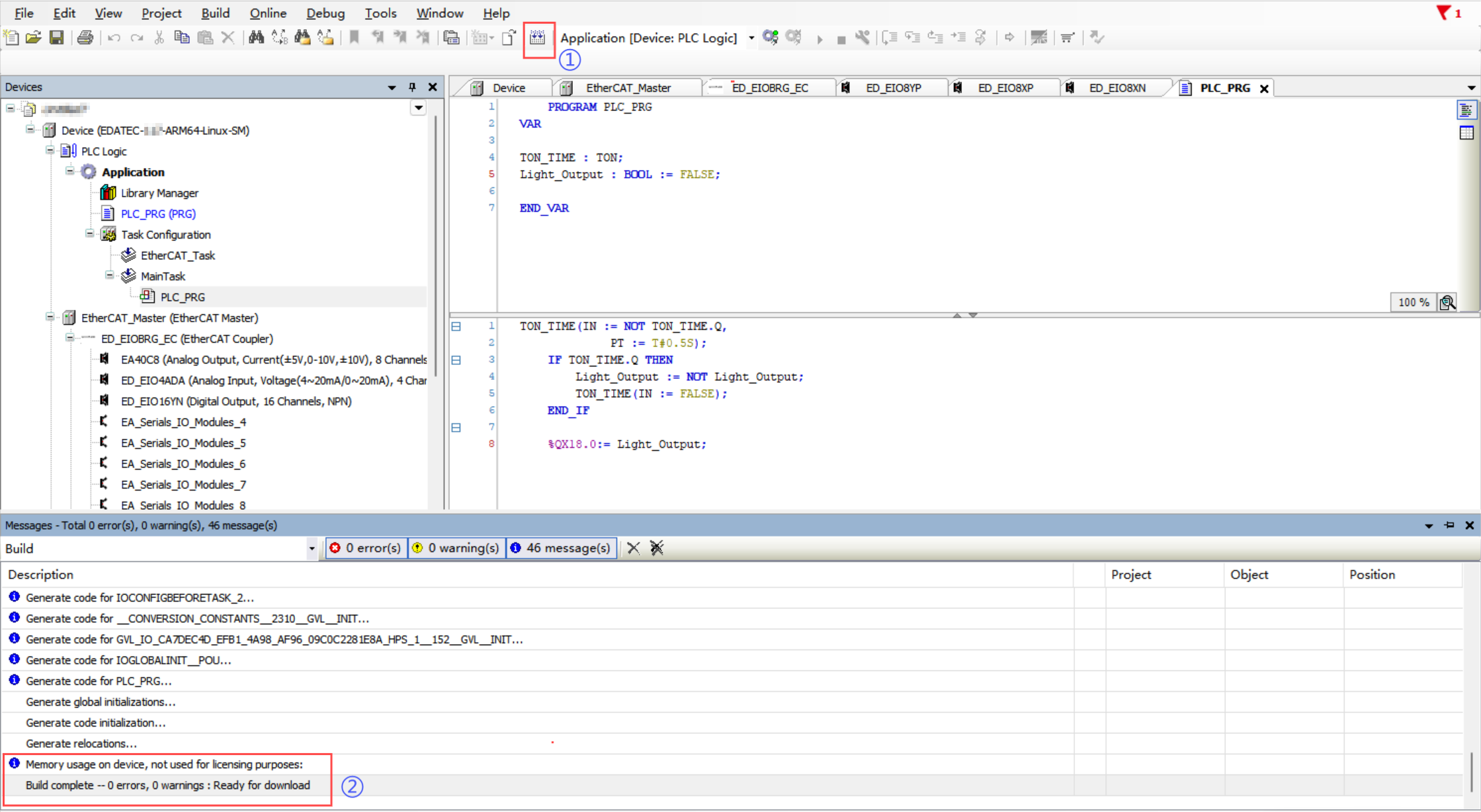
- After completing the program, click "
 " to compile it and ensure there are no errors.
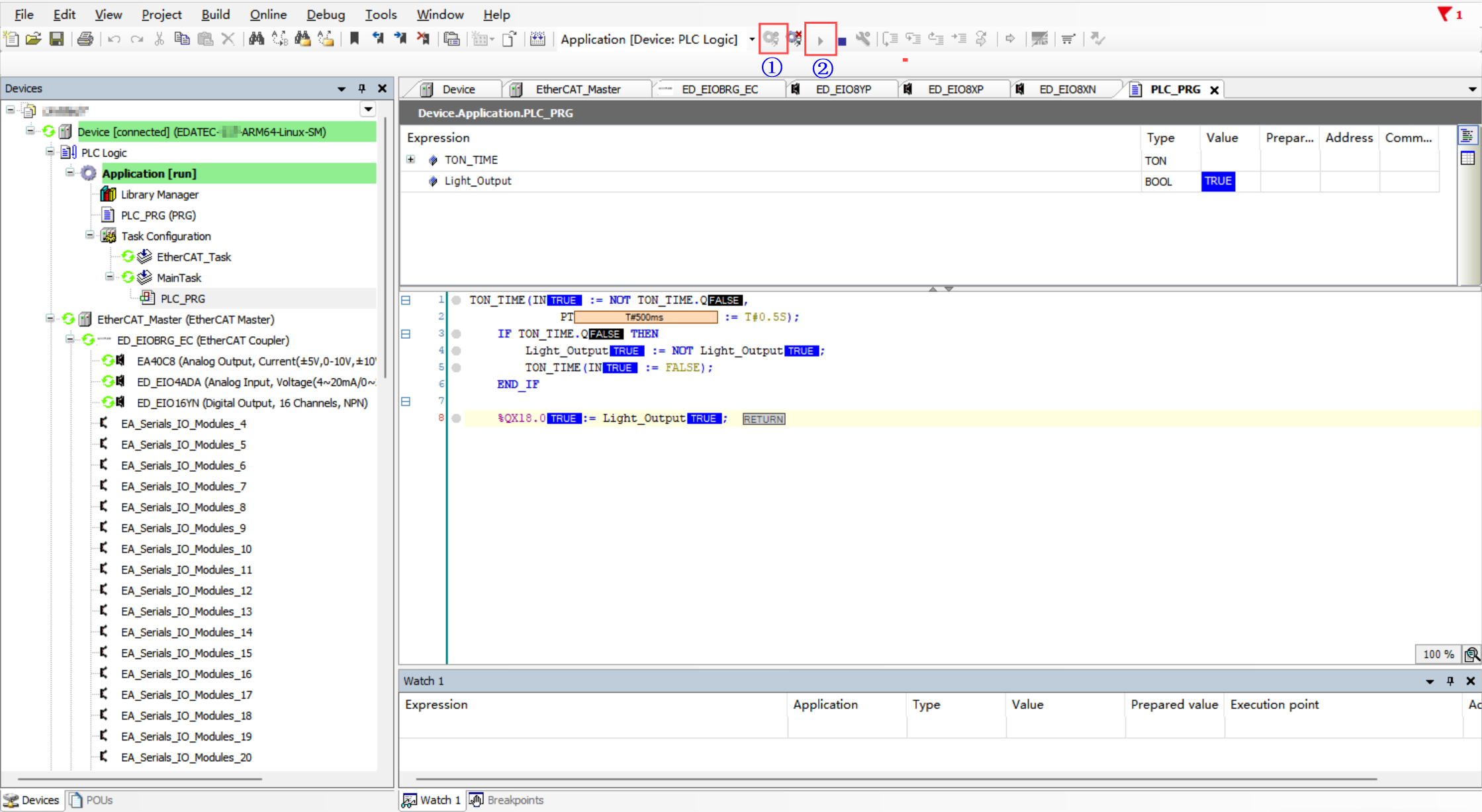
- Click Login to download the program to the device, then click Run to observe the LED blinking every 0.5 seconds.
4.5 Operation and Maintenance
After downloading the program to the device, you can perform the Run and Stop operations.
| Status | Operations |
|---|---|
| Run Program | In the main menu of the software interface, click the Login button |
| Stop Program | In the main menu of the software interface, click the stop  button. button. |