1 Hardware Manual
This chapter introduces the product overview, packing list, appearance, button, indicator and interface.
1.1 Overview
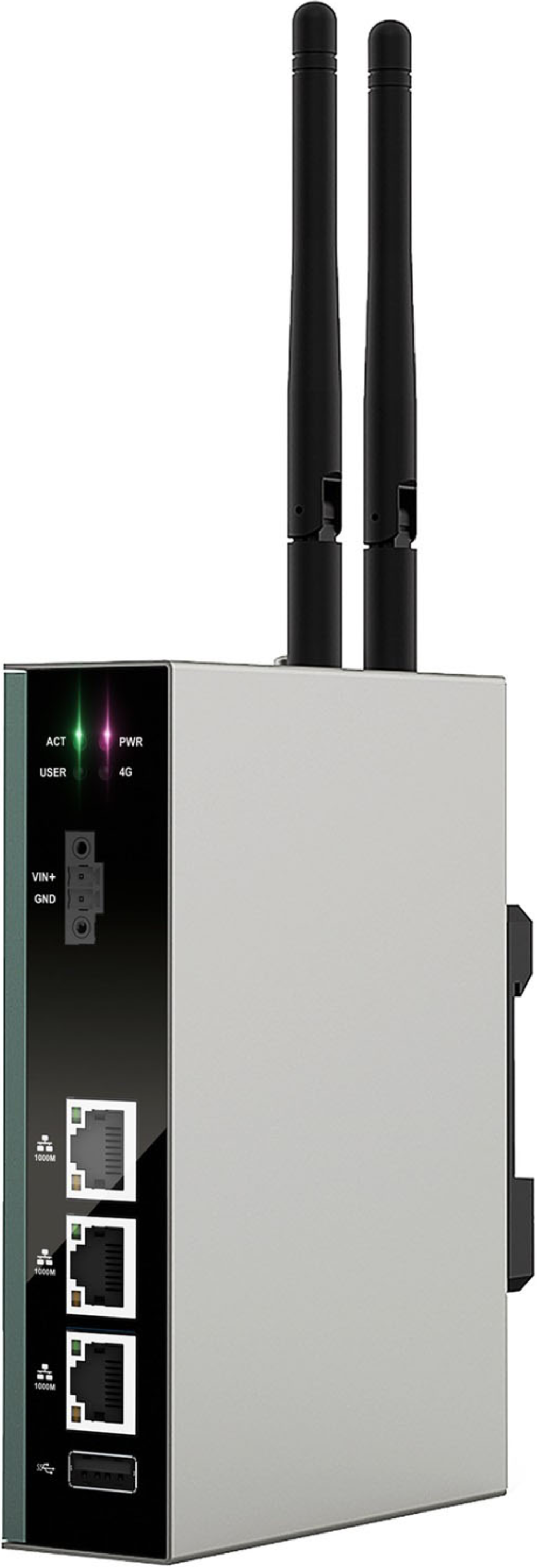
The ED-IPC3200 series is an industrial computer based on the Raspberry Pi CM5, comprising two models: ED-IPC3210 and ED-IPC3220. Users can select different RAM and eMMC configurations according to application scenarios and requirements.
- Options for 2GB, 4GB, 8GB and 16GB RAM
- Options for 16GB, 32GB and 64GB eMMC storage
The ED-IPC3200 provides standard interfaces including HDMI, USB 2.0, USB 3.0, Audio, and Ethernet. It supports network connectivity via Wi-Fi, Ethernet, or 4G. Integrated features such as supercapacitor backup power (optional), RTC (Real-Time Clock), Watch Dog, EEPROM, and an encryption chip enhance product reliability and user-friendliness. Designed for industrial control and IoT applications, it excels in demanding operational environments.
1.2 Packing List
- 1 x ED-IPC3200 Unit
- [Wi-Fi/BT Version - optional] 1 x 2.4GHz/5GHz Wi-Fi/BT Antenna
- [4G Version - optional] 1 x 4G/LTE Antenna
1.3 Appearance
Introducing the functions and definitions of interfaces on each panel.
1.3.1 Front Panel
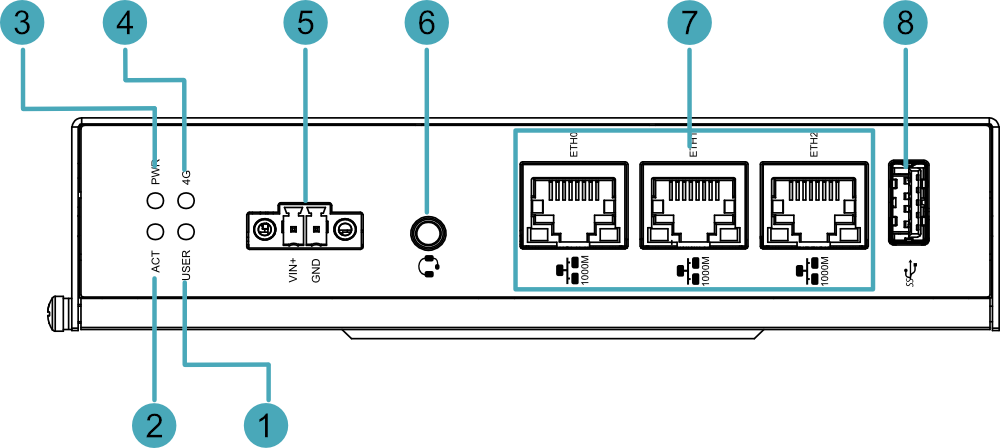
Introducing the front panel interface types and definitions.
| NO. | Function Definition |
|---|---|
| 1 | 1 x green user indicator, user can customize a status according to actual application. |
| 2 | 1 x green system status indicator, which is used to check the working status of device. |
| 3 | 1 x red power indicator, which is used to check the status of device power-on and power-off. |
| 4 | 1 x green 4G indicator, which is used to check the status of 4G signal. |
| 5 | 1 x DC input, 2-Pin 3.5mm pitch phoenix terminals with screw holes. It supports 9V~36V input, the signal is defined as "VIN+/GND". |
| 6 | 1 x Audio input/Stereo output, 3.5mm audio jack connector. It can be used as MIC IN and LINE OUT.
|
| 7 | 3 × 1000M Ethernet interfaces (ETH0 ~ ETH2), RJ45 connector with LED indicators, 10/100/1000M auto-sensing interfaces for Ethernet connection. |
| 8 | 1 × USB 3.0, Type-A connector, supporting transfer rates up to 5Gbps. |
1.3.2 Rear Panel
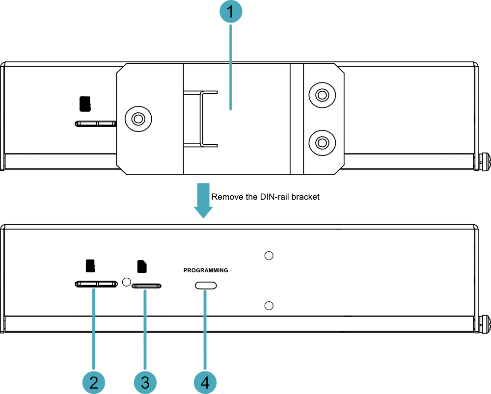
Introducing the types and definitions of the rear panel interface.
| NO. | Function Definition |
|---|---|
| 1 | 1 x DIN-rail bracket, install ED-IPC3200 Unit on the DIN-rail through the bracket. |
| 2 | 1 x Micro SD card slot, functionally reserved only. |
| 3 | 1 x Nano SIM card slot for installing a Nano SIM card to access 4G signals. |
| 4 | 1 x Micro USB port, it supports to flash to eMMC for the system. |
1.3.3 Side Panel
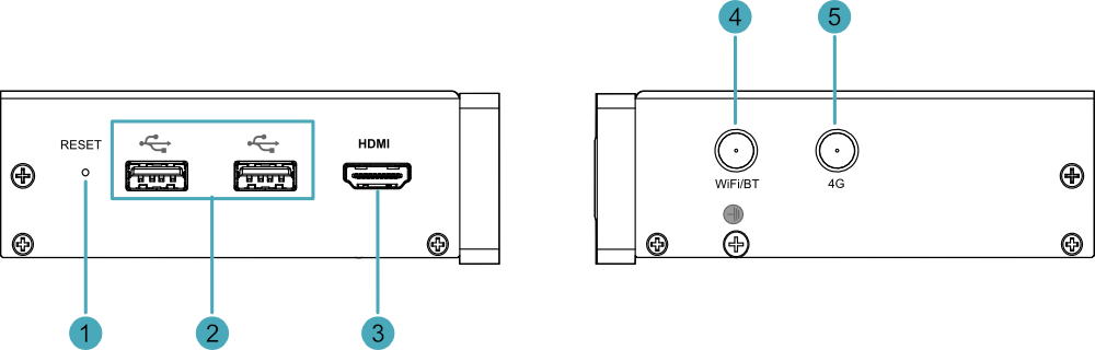
Introducing the types and definitions of side panel interfaces.
| NO. | Function Definition |
|---|---|
| 1 | 1 x Reset button, hidden button, press the button to restart the device. |
| 2 | 2 x USB 2.0 ports, Type-A connector, each channel supports up to 480Mbps transmission rate. |
| 3 | 1 x HDMI port, Type-A connector, which is compatibles with HDMI 2.0 standard and supports 4K 60Hz. It supports to connect a displayer. |
| 4 | 1 x Wi-Fi/BT antenna port (optional), SMA connector, which can connect to Wi-Fi/BT antenna. |
| 5 | 1 x 4G antenna port (optional), SMA connector, which can connect to 4G antenna. |
1.4 Button
ED-IPC3200 series device includes a RESET button, which is a hidden button, and the silkscreen on the case is "RESET". Pressing the RESET button will reset the device.
1.5 Indicator
Introducing the various statuses and meanings of indicators contained in ED-IPC3200 series device.
| Indicator | Status | Description |
|---|---|---|
| PWR | On | The device has been powered on. |
| Blink | Power supply of the device is abnormal, please stop the power supply immediately. | |
| Off | The device is not powered on. | |
| ACT | Blink | The system started successfully and is reading and writing data. |
| Off | The device is not powered on or does not read and write data. | |
| USER | On | User can customize a status according to actual application. |
| Off | The device is not powered on or not defined by the user, and the default status is off. | |
| 4G | On | The dial-up is successful and the connection is normal. |
| Off | 4G signal is not connected or the device is not powered on. | |
| Yellow indicator of Ethernet port | On | The data transmission is abnormal. |
| Blink | Data is being transmitted over the Ethernet port. | |
| Off | The Ethernet connection is not set up. | |
| Green indicator of Ethernet port | On | The Ethernet connection is in the normal state. |
| Blink | The Ethernet connection is abnormal. | |
| Off | The Ethernet connection is not set up. |
1.6 Interface
Introducing the definition and function of each interface in ED-IPC3200 device.
1.6.1 SIM Card Slot (optional)
The ED-IPC3200 device includes one Nano SIM card slot labeled with the silkscreen " ", which is used for installing a SIM card to access 4G signals.
1.6.2 Power Interface
The ED-IPC3200 device features one power input terminal, implemented as a 2-Pin 3.5mm-pitch phoenix connector. The interface is labeled with the silkscreen "VIN+/GND", and the pin definitions are as follows.
 | Pin ID | Pin Name |
|---|---|---|
| 1 | GND | |
| 2 | 9V~36V |
1.6.3 Audio Interface (optional)
ED-IPC3200 series device includes one audio input, the connector is a 3.5mm four-stage headphone jack. The silkscreen of port is " ", which supports OMTP stereo headphone output and mono microphone recording.
- When the headphone is connected, the audio output is switched to the headphone.
TIP
Only ED-IPC3220 features this interface.
1.6.4 1000M Ethernet Interface (ETH0 ~ ETH2)
The ED-IPC3200 device includes three auto-sensing 10/100/1000M Ethernet interfaces, labeled with the silkscreen " ". These interfaces utilize RJ45 connectors, and for Ethernet connectivity, it is recommended to use Category 6 (Cat6) or higher-specification network cables. The pin definitions for the terminals are as follows:
 | Pin ID | Pin Name |
|---|---|---|
| 1 | TX1+ | |
| 2 | TX1- | |
| 3 | TX2+ | |
| 4 | TX2- | |
| 5 | TX3+ | |
| 6 | TX3- | |
| 7 | TX4+ | |
| 8 | TX4- |
1.6.5 HDMI Interface
The ED-IPC3200 device features one HDMI interface with a silkscreen label "HDMI", designed as a standard Type-A connector. It supports connection to HDMI displays and delivers video output up to 4K resolution at 60Hz (4K@60).
1.6.6 USB 2.0 Interface
The ED-IPC3200 device features two USB 2.0 interfaces, labeled with the silkscreen " ". These utilize standard Type-A connectors, supporting connectivity with standard USB 2.0 peripherals and providing data transfer speeds up to 480 Mbps.
1.6.7 USB 3.0 Interface
The ED-IPC3200 device is equipped with one USB 3.0 port. The port is marked with a silk-screened label " " and features a standard Type-A connector. It supports connection to standard USB 3.0 peripherals, delivering transfer speeds of up to 5Gbps.
1.6.8 Micro USB Interface
The ED-IPC3200 device includes one Micro USB interface with a silkscreen label "PROGRAMMING". It supports flashing to eMMC when connected to a PC.
1.6.9 Antenna Interface (optional)
The ED-IPC3200 device is equipped with up to two SMA antenna ports. These ports are silk-screened with "4G" and "WiFi/BT", respectively, designated for connecting the 4G antenna and Wi-Fi/BT antenna.
TIP
The number of antenna ports varies depending on the user's specific model configuration. Here, the version equipped with two antenna ports is used as an example for illustration.
1.7 Supercapacitor (Optional)
The ED-IPC3200 supports an optional supercapacitor backup power module, featuring a comprehensive safe shutdown protection mechanism.
- In the event of an unexpected power failure when the supercapacitor is fully charged, the system can automatically switch to supercapacitor power supply, allowing the device to continue normal operation until the capacitor's charge is depleted. It then automatically shuts down safely, effectively preventing operational interruptions and data loss.
- The device provides user-customizable emergency scripts, supporting pre-configuration of critical data saving, backup, or other emergency procedures. At the moment of power loss, the system will automatically execute the preset scripts to ensure critical operations are completed, allowing for a composed response to sudden power outages.
TIP
- For specific operations on customizing supercapacitor-related parameters, please refer to AN18 Supercapacitor Usage Guide.
- The supercapacitor requires the device to be powered on for at least 5 minutes to fully charge, and normal functionality is only guaranteed when it is fully charged.