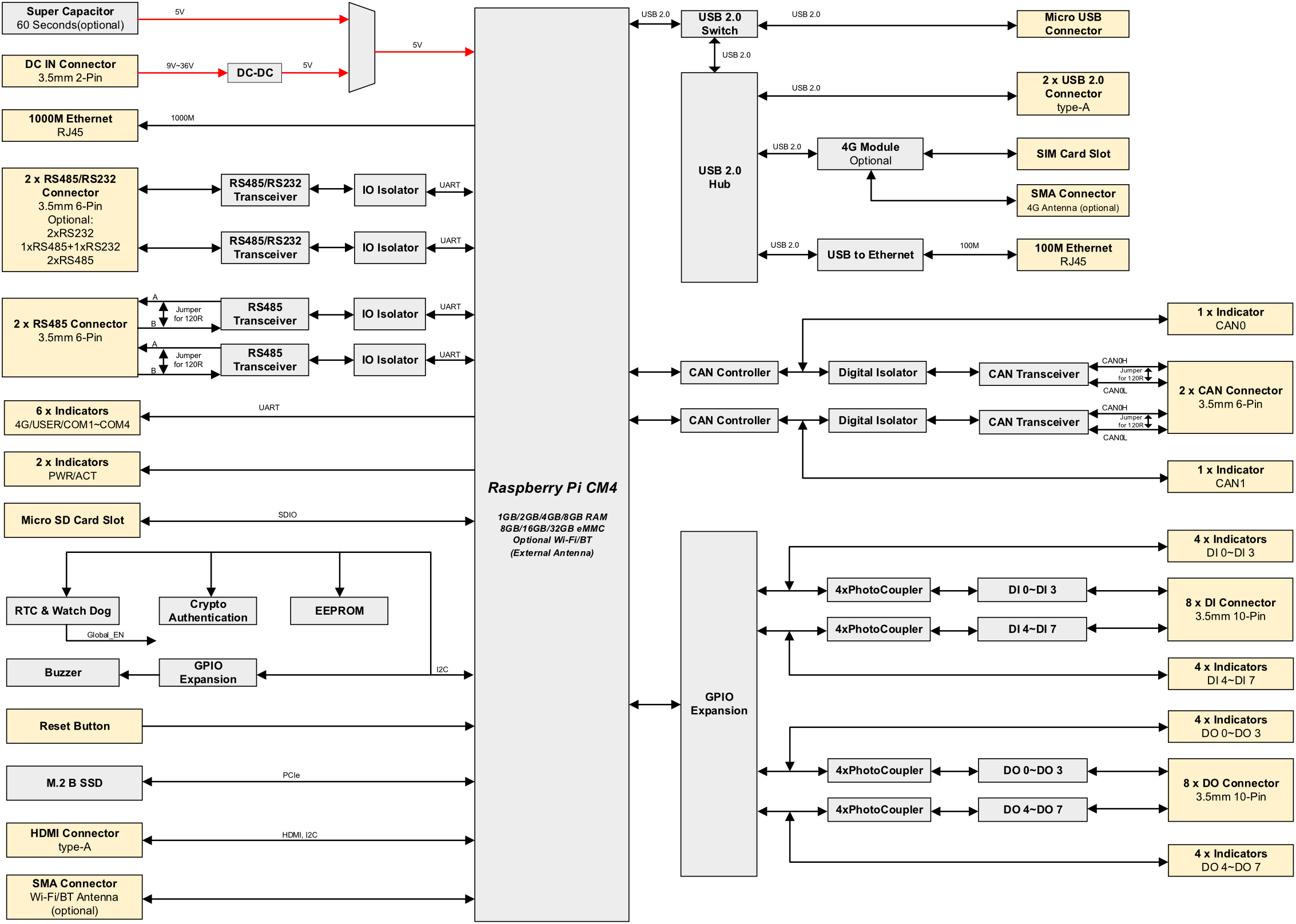
Industrial Computer Based on Raspberry Pi CM4
- Broadcom BCM2711, quad core Arm Cortex-A72 (ARM v8) 64-bit SoC @ 1.5GHz
- Up to 8GB LPDDR4 RAM and 32GB eMMC storage, support Micro SD Card and M.2 NVMe SSD storage expansion
- Dual Lans, 1 x Gigabit Ethernet and 1 x 100M Ethernet
- 4 x isolated RS232/RS485 with electrostatic and surge protection
- 2 x isolated CAN with led indicator, support CAN 2.0B standard
- 8 x isolated DI with led indicator, support AC input
- 8 x isolated DO with led indicator, support overcurrent protection
- 2.4GHz and 5GHz Wi-Fi, Bluetooth and 4G LTE
- Optional CODESYS Control for Raspberry Pi MC SL
- Wide voltage power input range of DC 9V~36V with reverse polarity protection, overvoltage protection and overcurrent protection
- Integrated supercapacitor backup power (optional), RTC, Watch Dog, EEPROM and encryption chip
- Wide temperature range of -25℃~60℃ for working environment
- High-quality metal case, compatible with DIN-rail installation
|  |
| System |
|---|
| CPU | Broadcom BCM2711, quad core Arm Cortex-A72 (ARM v8) 64-bit SoC @ 1.5GHz |
| VPU | H.265 (HEVC), up to 4Kp60 decode
H.264, up to 1080p60 decode, 1080p30 encode |
| GPU | OpenGL ES 3.1 & Vulkan 1.0 |
| Memory | Options for 1GB, 2GB, 4GB, 8GB LPDDR4-3200 SDRAM |
| Storage | Options for 8GB, 16GB, 32GB eMMC storage
Micro SD card slot (user storage expansion)
M.2 NVMe SSD (options for 128GB, 256GB, 512GB) |
| Software |
|---|
| Operating System | Raspberry Pi OS (Desktop) 32-bit
Raspberry Pi OS (Lite) 32-bit
Raspberry Pi OS (Desktop) 64-bit
Raspberry Pi OS (Lite) 64-bit |
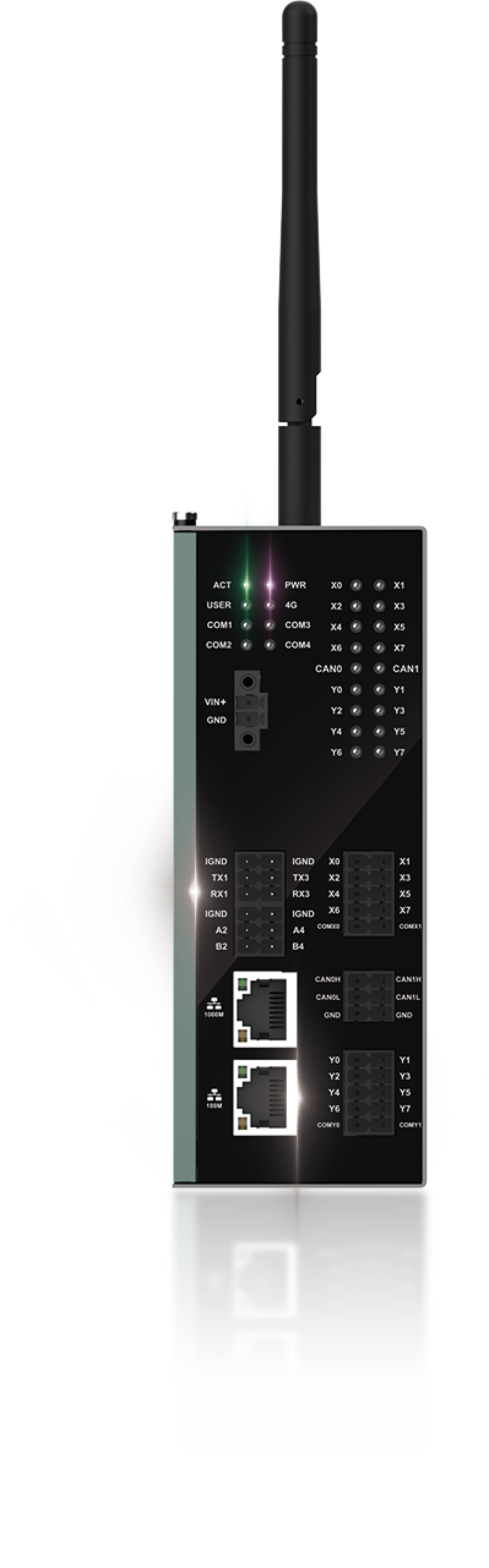
| Front I/O |
|---|
| Power | 1 x DC IN, 2-Pin 3.5mm pitch phoenix terminals with screw holes. It supports 9V~36V input, the signal is defined as VIN+/GND. |
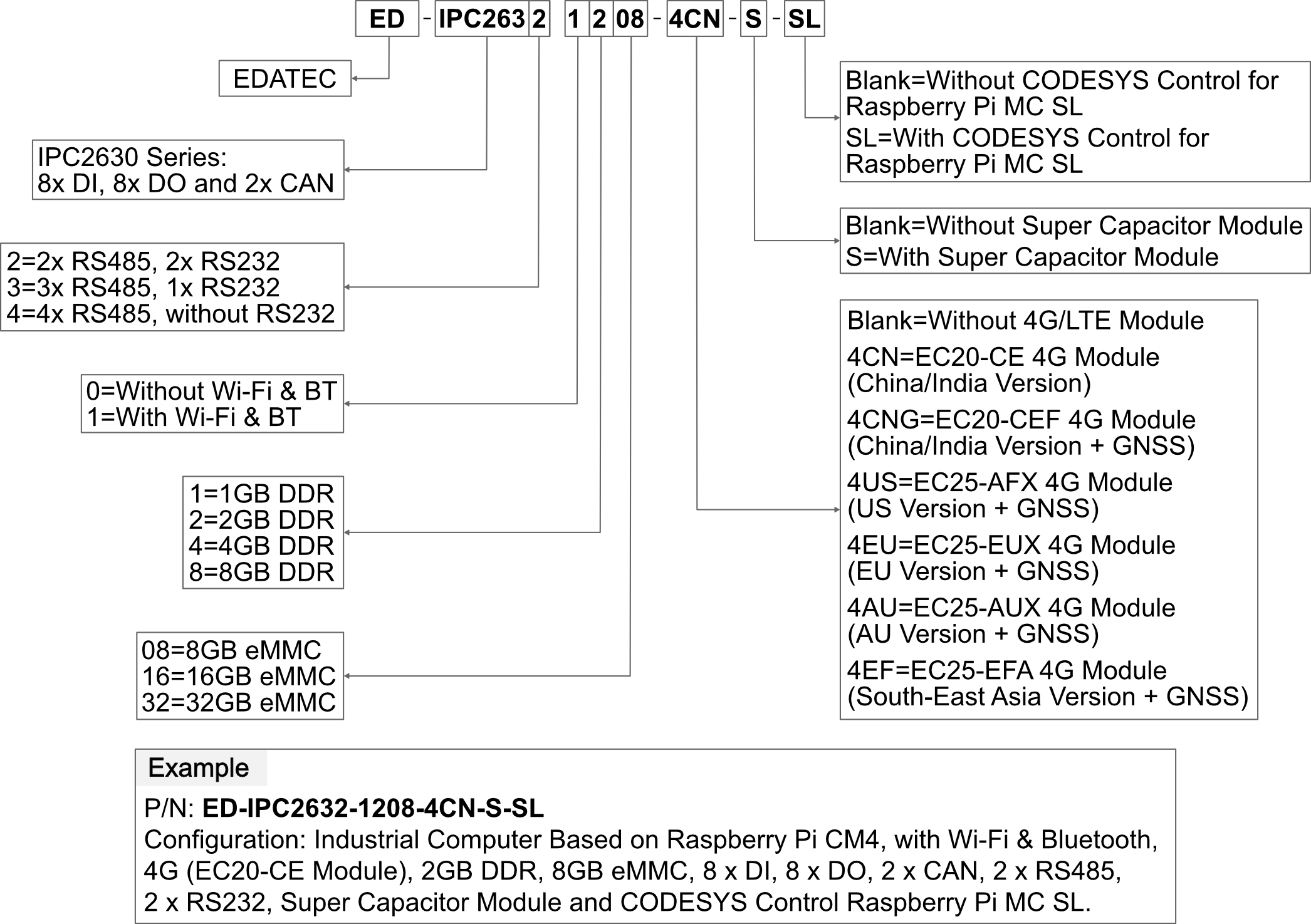
| RS485/232 | 12-Pin 3.5mm pitch phoenix terminals with IO isolator, which are equipped with electrostatic and surge protection. Different numbers of RS232 and RS485 ports can be selected according to actual application. The signal of RS485 is defined as IGND/A/B, and the signal of RS232 is defined as IGND/TX/RX. - ED-IPC2632:2 x RS485 + 2 x RS232
- ED-IPC2633:3 x RS485 + 1 x RS232
- ED-IPC2634:4 x RS485
|
| 1000M Ethernet | 1 x adaptive 10/100/1000M ethernet port, RJ45 connector. It can be used to access the network. |
| 100M Ethernet | 1 x adaptive 10/100M ethernet port, RJ45 connector. It can be used to access the network. |
| CAN | 2 x CAN ports, 6-Pin 3.5mm pitch phoenix terminals
- Isolation Protection: 3 KV
- CAN Protocol: CAN 2.0B
- Baud Rate: 10~1000 kbps
- Signals: CANH, CANL, GND
|
| DI | 8 x DI ports, 10-Pin 3.5mm pitch phoenix terminals
- Sensor Type: Wet Contact (NPN & PNP), Dry Contact
- Isolation Protection: 5 KV
- Every 4 DI share one common pin (called COM): X0, X2, X4 and X6 share COMX0; X1, X3, X5 and X7 share COMX1
- DI to COM:
ON: 5~30 VDC or -30~-5 VDC
OFF: 0~2 VDC or -2~0 VDC
|
| DO | 8 x DO ports, 10-Pin 3.5mm pitch phoenix terminals
- Sensor Type: NPN
- Isolation Protection: 5 KV
- Output: 5~36 VDC (24 VDC is recommended), maximum current is 1.5A (per channel)
|
| Rear I/O |
|---|
| SD Card Slot | 1 x Micro SD card slot, which is used to install Micro SD card for storing user data. |
| SIM Card Slot | 1 x Nano SIM card slot, which is used to install Nano SIM card for getting 4G signal. |
| Micro USB | 1 x Micro USB port, which supports to flash to eMMC for the system. |
| Side I/O |
|---|
| HDMI | 1 x HDMI port, Type-A connector. It is compatible with HDMI 2.0 standard and supports 4K 60Hz. |
| USB 2.0 | 2 x USB 2.0 ports, Type-A connector, supporting up to 480Mbps transmission rate. |
| Antenna | 2 x SMA ports (optional), using to connect 4G antenna and Wi-Fi/BT antenna. |
| Buttons and Indicators |
|---|
| Reset | 1 x Reset button, which can reset the device. |
| PWR | 1 x red power indicator, which is used to check the status of device power-on and power-off. |
| 4G | 1 x green 4G indicator, which is used to check the status of 4G signal. |
| ACT | 1 x green system indicator, which is used to check the working status of device. |
| USER | 1 x green user indicator, user can customize a status according to actual application. |
| COM1~COM4 | 4 x green UART indicators, using to check the communication status of UART ports. |
| CANB0~CANB1 | 2 x green CAN indicators, using to check the communication status of CAN ports.
NOTE: In the old version of the product, the silkscreen for the CAN indicators were labeled as "CAN0" and "CAN1". |
| X0~X7 | 8 x green DI indicators, using to check the input status of DI ports. |
| Y0~Y7 | 4 x green DO indicators, using to check the output status of DO ports. |
| Internal I/O |
|---|
| M.2 B | 1 x M.2 B, M.2 B Key connector, supporting to connect SSD. It is compatible with M.2 B 2230 and M.2 B 2242 SSD. |
| Expansion Functions |
|---|
| EEPROM | Supports 4K byte storage and improves the ease of use of device. |
| Crypto Authentication | It can be matched to realize the required upper layer application and improves the security of device. |
| RTC | RTC with 1F SuperCAP backup, which can ensure that the system clock is not affected by device power-off. We also provide a battery base, and you can buy a CR1220 battery backup for RTC. |
| Buzzer | A tip or an abnormity can be configurated according to actual application, which realizes the alarm function. |
| Watch Dog* | This function has been reserved on hardware. But we need additional software to support it, which is under development. |
| Electrical Characteristics |
|---|
| Input Voltage | 9V ~ 36V DC |
| Power Consumption | 24W (Max) |
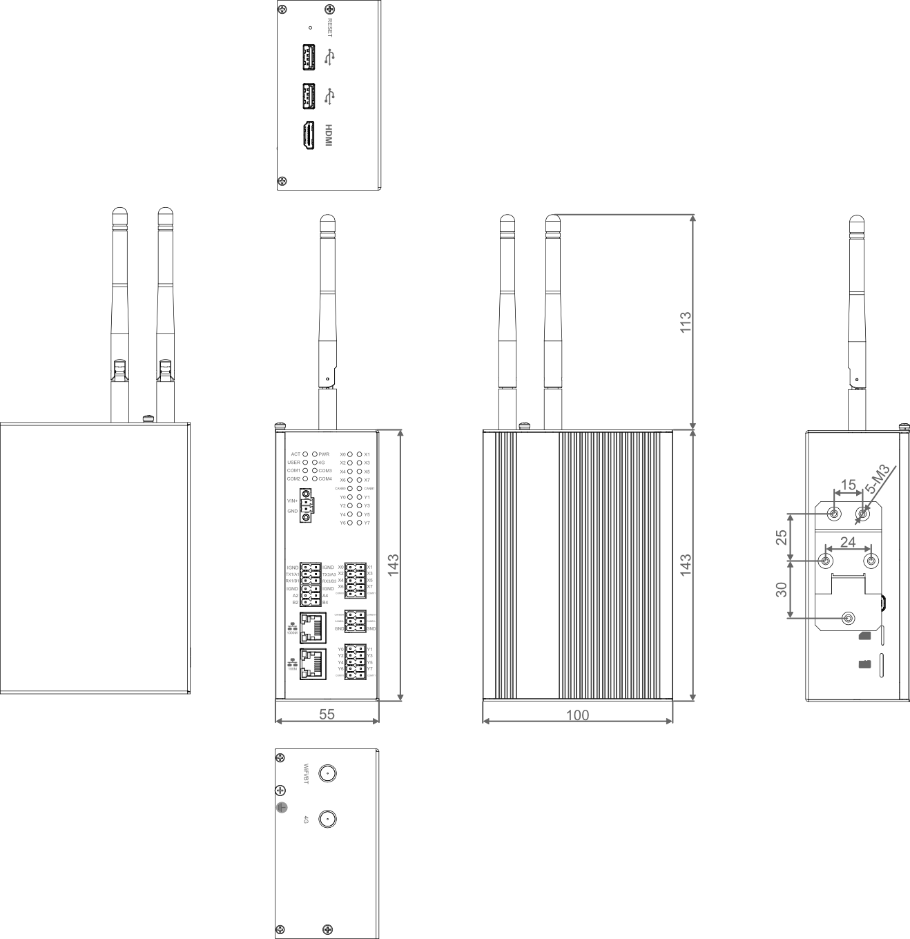
| Mechanical Characteristics |
|---|
| Dimensions | 143mm x 100mm x 55mm (WxDxH, DIN-rail and antenna are not included.) |
| Weight | 1kg |
| Installation | DIN-rail mounting |
| Wireless |
|---|
| Wi-Fi/Bluetooth (optional) | 2.4GHz & 5GHz dual-band Wi-Fi and Bluetooth 5.0 with antenna - 2.4GHz Wi-Fi: Compatible with IEEE 802.11 b/g/n
- 5GHz Wi-Fi: Compatible with IEEE 802.11 a/n/ac
- The Bluetooth supports 2402MHz ~ 2480MHz frequency.
|
| 4G (optional) | Connect with various 4G LTE modules through the Mini PCIe interface, with antenna. - EC20-CE Module (China/India)
- LTE FDD: B1/B3
- LTE TDD: B38/B39/B40/B41
- TDSCDMA: B34/B39
- WCDMA: B1
- CDMA 1x/EVDO: BC0
- GSM: 900/1800MH
- GPS/GLONASS/BDS/Galileo/QZSS (optional)
- EC25-AFX Module (North America)
- LTE FDD: B2/B4/B5/B12/B13/B14/B66/B71
- LTE TDD
- WCDMA: B2/B4/B5
- GSM/EDGE
- GPS/GLONASS/BDS/Galileo/QZSS
- EC25-AUX Module (Latin America/Australia/New Zealand)
- LTE FDD: B1/B2/B3/B4/B5/B7/B8/B28
- LTE TDD: B40
- WCDMA: B1/B2/B4/B5/B8
- GSM/EDGE: B2/B3/B5/B8
- GPS/GLONASS/BDS/Galileo/QZSS
- EC25-EUX Module (Europe/Middle East/Africa/Thailand)
- LTE FDD: B1/B3/B7/B8/B20/B28A
- LTE TDD: B38/B40/B41
- WCDMA: B1/B8
- GSM/EDGE: B3/B8
- GPS/GLONASS/BDS/Galileo/QZSS
- EC25-EFA Module (Europe/Middle East/Africa/South-East Asia)
- LTE FDD: B1/B3/B7/B8/B20/B28
- LTE TDD: B38/B40/B41
- WCDMA: B1/B5/B8
- GSM/EDGE: B3/B8
- GPS/GLONASS/BDS/Galileo/QZSS
|
| Environmental & Regulatory |
|---|
| Operating Temperature | -25°C ~ 60°C |
| Storage Temperature | -25°C ~ 60°C |
| Ambient humidity | 5% ~ 95% (non-condensing) |
| Certifications | - FCC
- FCC 47 CFR Part 15 Subpart B
- CE
- EN IEC 62368-1:2020 + A11:2020
- EN IEC 62311:2020
- ETSI EN 301 489-1 V2.2.3 (2019-11)/Draft ETSI EN 301 489-17 V3.2.6 (2023-06)
ETSI EN 301 489-52 V1.2.1 (2021-11)/EN 55032:2015 + A1:2020 + A11:2020
EN 55035:2017 + A11:2020/EN IEC 61000-3-2:2019 + A1:2021
EN 61000-3-3:2013 + A1:2019 + A2:2021 - ETSI EN 300 328 V2.2.2 (2019-07)/ETSI EN 301 893 V2.1.1 (2017-05)
ETSI EN 301 908-1 V15.2.1 (2023-01)/ETSI EN 301 908-13 V13.2.1 (2022-02)
|
Unit: mm
TIP
In the older version of the product, the silkscreen for the CAN interfaces were marked as "CAN0H/CAN0L/GND" and "CAN1H/CAN1L/GND", and the silkscreen for the CAN indicators were labeled as "CAN0" and "CAN1".
You can choose a power adapter according to actual needs.
| Model | Description | Picture |
|---|
| ED-PSU1202-UK-3.5PL | 100~240VAC to12VDC/2A Adapter, with UK AC plug, 3.5mm pitch phoenix plug with lock | 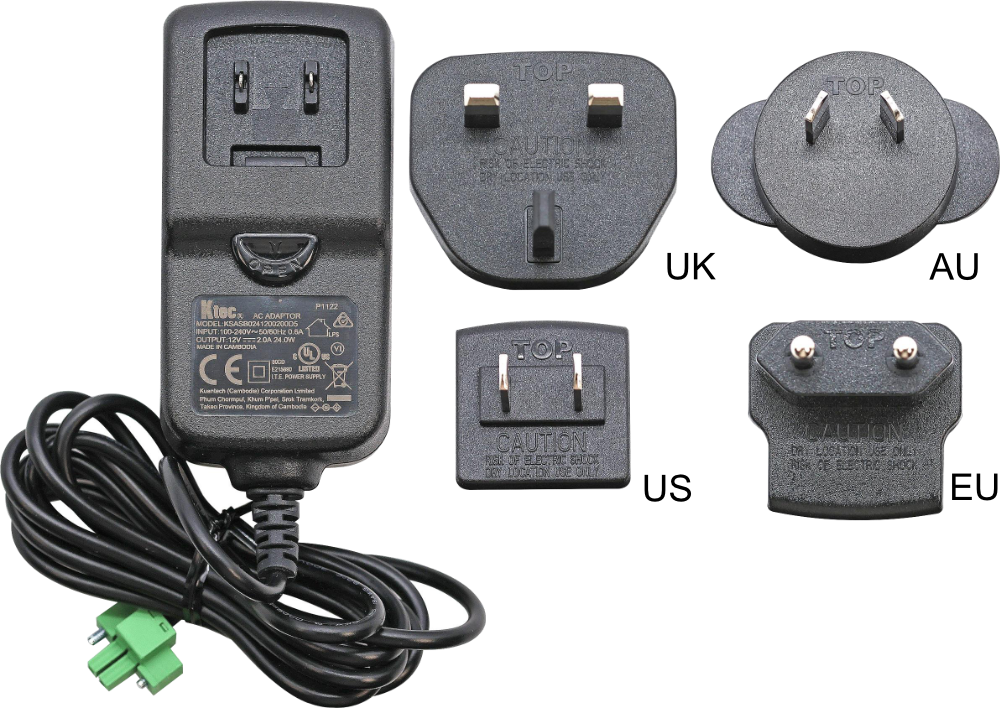 |
| ED-PSU1202-US-3.5PL | 100~240VAC to 12VDC/2A Adapter, with US AC plug, 3.5mm pitch phoenix plug with lock |
| ED-PSU1202-AU-3.5PL | 100~240VAC to 12VDC/2A Adapter, with AU AC plug, 3.5mm pitch phoenix plug with lock |
| ED-PSU1202-EU-3.5PL | 100~240VAC to 12VDC/2A Adapter, with EU AC plug, 3.5mm pitch phoenix plug with lock |
| NOTE: Each model contains only one of the UK, US, AU and EU plugs. |
- 1 x ED-IPC2630 Unit
- [WiFi/BT Version - optional] 1 x 2.4GHz/5GHz Wi-Fi/BT Antenna
- [4G Version - optional] 1 x 4G/LTE Antenna