1 Hardware Manual
This chapter introduces the product overview, packing list, appearance, button, indicator, and interface.
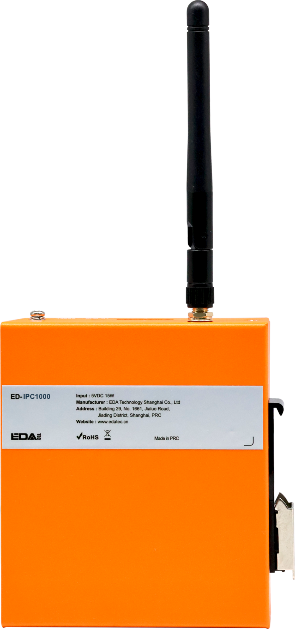
1.1 Overview
The ED-IPC1000 is a low-cost industrial computer based on the Raspberry Pi CM0, featuring 512MB of RAM as standard. Depending on the application scenario and user requirements, it supports customizable configurations with eMMC or an SD card.
- Available eMMC options include 8GB and 16GB.
- The available SD card option is 32GB.
The ED-IPC1000 provides commonly used interfaces such as HDMI, USB, and Ethernet, and supports network connectivity via Wi-Fi or Ethernet. It integrates an RTC and Watch Dog, making it primarily suitable for industrial control and Internet of Things (IoT) applications.
1.2 Packing List
- 1 x ED-IPC1000 Unit
- [Optional Wi-Fi/BT Version] 1 x 2.4GHz Wi-Fi/BT Antenna
1.3 Appearance
Introduce the functions and definitions of the interfaces on each panel.
1.3.1 Front Panel
Introduce the types and definitions of the front panel interfaces.

| NO. | Function Definition |
|---|---|
| 1 | 1 x red power indicator, used to display the device's power on/off status. |
| 2 | 1 x green system status indicator, used to monitor the device's operating status. |
| 3 | 1 x adaptive 10/100M ethernet port, RJ45 connector. It can be used to access the network. |
| 4 | 2 x USB 2.0 ports, stacked Type-A connector, each supporting a maximum data transfer rate of 480Mbps. |
| 5 | 1 x HDMI port, Type-A connector, compliant with HDMI 1.3a standard, supports 1080p resolution at 30Hz and display connectivity. |
| 6 | 1 x DC input, USB Type-C connector, supports 5V input. |
1.3.2 Rear Panel
Introducing the types and definitions of the rear panel interface.

| NO. | Function Definition |
|---|---|
| 1 | 1 x Rail mounting bracket, used to install the ED-IPC1000 unit on a DIN rail via the bracket. |
| 2 | 1 x Micro SD card slot, supports inserting a Micro SD card for system boot. Note: The system supports booting from a Micro SD card only when the ED-IPC1000 is equipped with a CM0Lite. |
1.3.3 Side Panel
Introducing the types and definitions of side panel interfaces.

| NO. | Function Definition |
|---|---|
| 1 | Heat dissipation holes, which help improve cooling performance. |
| 2 | 1 x Wi-Fi/BT antenna port (optional), SMA connector, for connecting the Wi-Fi/BT antenna. |
| 3 | 1 x RTC battery port (default installed rubber plug), supports installation of an RTC battery (CR2032) via this port. |
| 4 | 1 x DIP switch, supports switching between normal operation mode and flashing mode.
|
| 5 | 1 x reset button, recessed design, pressing the button restarts the device. |
| 6 | 1 x Grounding point, for connecting to the earth ground of an external power supply. |
1.4 Button
The ED-IPC1000 device includes one RESET button, which is a recessed button marked with "RESET" on the casing silkscreen. Pressing the RESET button reboots the device.
1.5 Indicator
Introduce the various states and meanings of the indicator included in the ED-IPC1000.
| Indicator | Status | Description |
|---|---|---|
| PWR | On | The device has been powered on. |
| Blink | Power supply of the device is abnormal, please stop the power supply immediately. | |
| Off | The device is not powered on. | |
| ACT | Blink | The system started successfully and is reading and writing data. |
| Off | The device is not powered on or does not read and write data. | |
| Green indicatorof Ethernet port | On | The Ethernet connection is abnormal. |
| Blink | Data is being transmitted over the Ethernet port. | |
| Off | The Ethernet connection is not set up. | |
| Yellow indicatorof Ethernet port | On | The Ethernet connection is in the normal state. |
| Blink | The Ethernet connection is abnormal. | |
| Off | The Ethernet connection is not set up. |
1.6 Interface
Introduce the definitions and functions of the various interfaces in the product.
1.6.1 Micro SD Card Slot
The ED-IPC1000 device includes one Micro SD card slot, with the slot interface silkscreened as "  ". It supports the installation of a Micro SD card to boot the system.
TIP
- Booting from a Micro SD card is supported only when the ED-IPC1000 is equipped with a CM0Lite.
- When the ED-IPC1000 uses a CM0 with 8GB or 16GB eMMC, the Micro SD card slot is a non-functional interface.
1.6.2 Power Interface
The ED-IPC1000 device features one power input interface using a USB Type-C connector, with the interface silkscreened as "DC IN". It supports 5V power input.
1.6.3 100M Ethernet Interface
The ED-IPC1000 device includes one adaptive 10/100M Ethernet interface, with the interface silkscreened as " ". It uses an RJ45 connector, and when connecting to Ethernet, it is recommended to use a network cable of Cat6 or above specification. The pin definitions corresponding to the connector are as follows:
 | Pin ID | Pin Name |
|---|---|---|
| 1 | TX+ | |
| 2 | TX- | |
| 3 | Rx+ | |
| 4 | - | |
| 5 | - | |
| 6 | RX- | |
| 7 | - | |
| 8 | - |
1.6.4 HDMI Interface
The ED-IPC1000 device includes one HDMI interface, silkscreened as "HDMI", which is a standard Type-A connector. It is compatible with HDMI displays and supports video output of up to 1080p30.
1.6.5 USB 2.0 Interface
The ED-IPC1000 device includes two USB 2.0 interfaces, silkscreened as " ", which are standard dual-layer Type-A connectors. They support connection with standard USB 2.0 peripherals and offer a maximum transmission rate of 480 Mbps.
1.6.6 Antenna Interface (optional)
If the selected ED-IPC1000 device includes Wi-Fi/BT functionality, it features one SMA antenna interface silkscreened as "WiFi/BT" for connecting the Wi-Fi/BT antenna.
1.6.7 RTC Battery Interface
The ED-IPC1000 device includes one RTC battery interface (default installed with a rubber plug), which supports the installation of an RTC battery.
TIP
- The supported battery model is CR2032.
- Before installing the battery, please confirm the positive and negative poles of the battery, and install it according to the positive and negative pole indications on the port silkscreen.
1.6.8 DIP Switch
The ED-IPC1000 device includes one DIP switch that supports switching between normal operation mode (default state) and flashing mode.
- LD: Flashing mode. In this mode, the device allows flashing to eMMC via the Type-C port when connected to a PC.
- RUN: Normal operation mode. In this mode, the device functions normally.
WARNING
The default state of the DIP switch is normal operation mode (RUN). Incorrect operation may affect the normal use of the device. Please proceed with caution.