1 Hardware Manual
This chapter introduces the product overview, packing list, appearance, button, indicator and interface.
1.1 Overview
ED-HMI2630-101C is an industrial HMI based on Raspberry Pi CM4. According to different application scenarios and user needs, different specifications of RAM and eMMC computer systems can be selected.
- RAM can choose 1GB, 2GB, 4GB and 8GB.
- eMMC can choose 8GB, 16GB and 32GB.
ED-HMI2630-101C provides common interfaces such as HDMI, USB, Ethernet, RS232, RS485, DI, DO and CAN, and supports network access through Wi-Fi, Ethernet and 4G; integrated supercapacitor backup power supply (optional), RTC, Watch Dog, EEPROM, and encryption chip, which enhances the ease of use and reliability of the product, which is mainly used in the field of industrial control and IOT.

1.2 Packing List
- 1x ED-HMI2630-101C Unit
1.3 Appearance
Introducing the functions and definitions of interfaces on each panel.
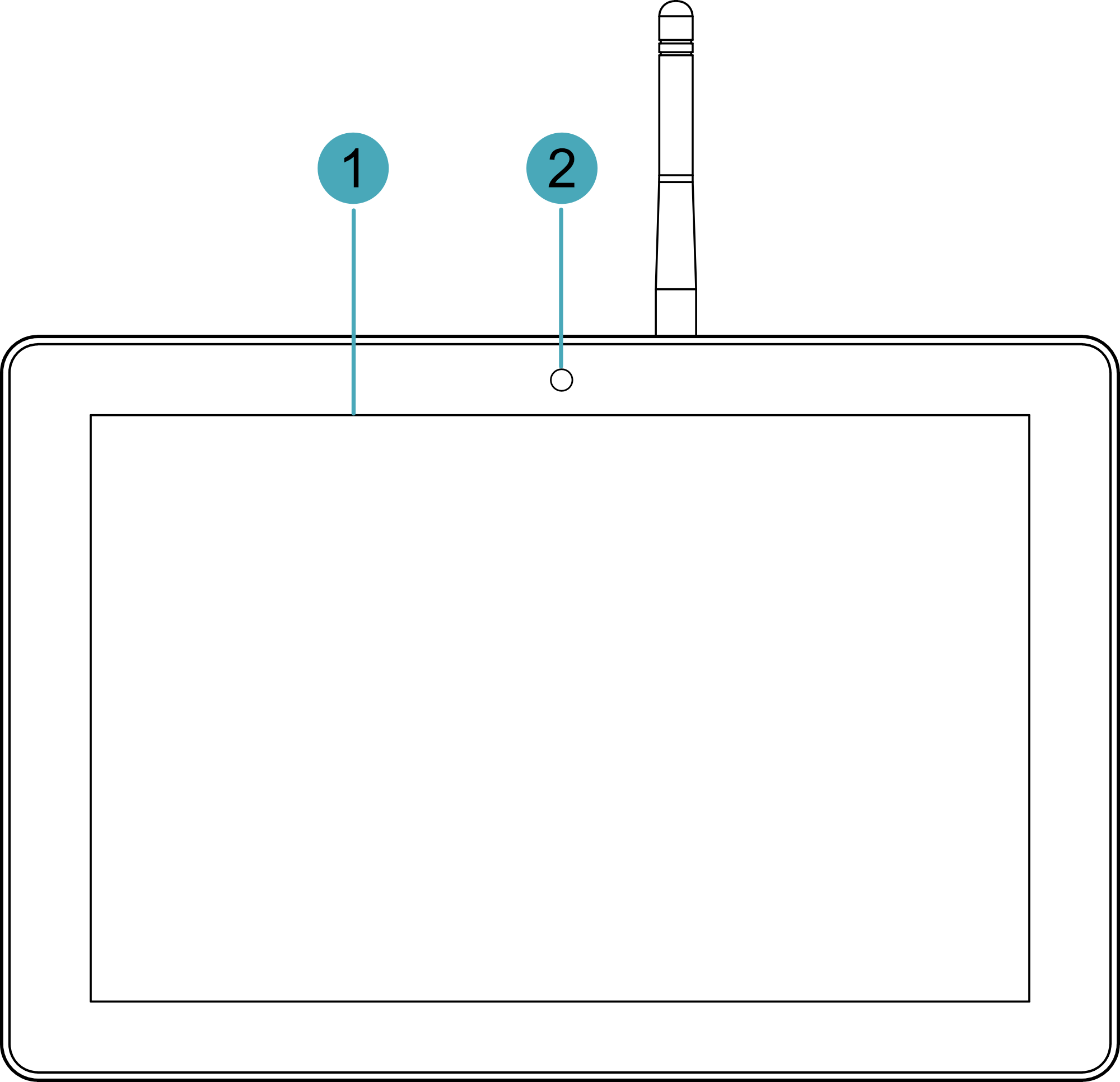
1.3.1 Front Panel
This section introduces functions and definitions of front panel.
| NO. | Function Definition |
|---|---|
| NO. | Function Definition |
| 1 | 1 x LCD display, 10.1-inch LCD touch screen, which supports up to 1280x800 and multi-point capacitive touchscreen. |
| 2 | 1 x Camera (optional), 8-megapixel front camera. |
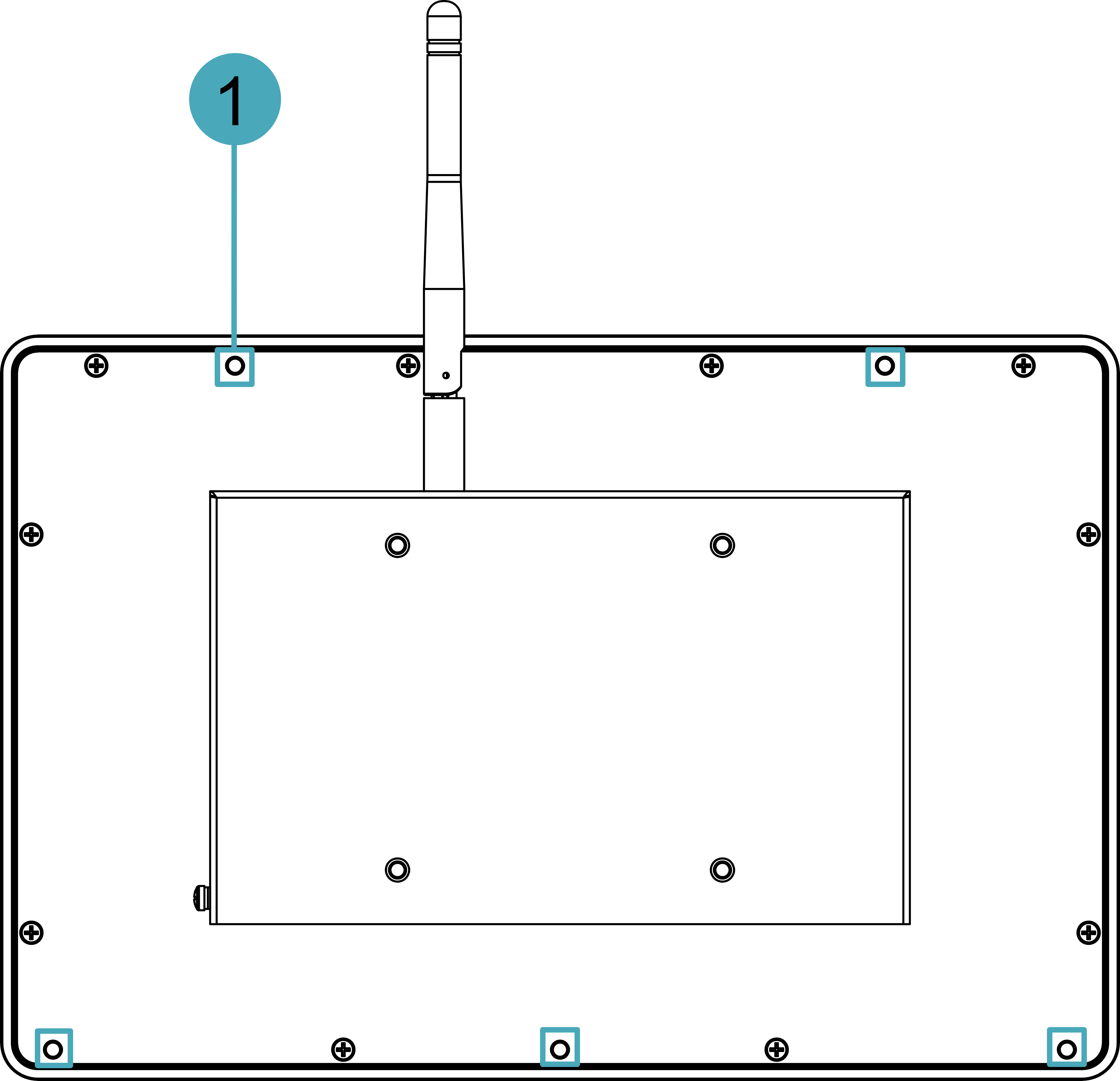
1.3.2 Rear Panel
This section introduces interfaces and definitions of rear panel.
| NO. | Function Definition |
|---|---|
| 1 | 5 x installation holes of buckle, which are used to fix the buckles to the device for installation. You only need to use 4 installation holes during installation, and reserve one as a spare. |
1.3.3 Side Panel
This section introduces interfaces and definitions of side panel.

TIP
In the older version of the product, the silkscreen for the CAN interfaces were marked as "CAN0H/CAN0L/GND" and "CAN1H/CAN1L/GND", and the silkscreen for the CAN indicators were labeled as "CAN0" and "CAN1".
| NO. | Function Definition |
|---|---|
| 1 | 1 x HDMI port, type-A connector, which is compatible with HDMI2.0 standard and supports 4K 60Hz. It supports to connect a displayer. |
| 2 | 2 x USB 2.0 ports, type-A connector, each channel supports up to 480Mbps. |
| 3 | 1 x Reset button, hidden button, press the button to restart the device. |
| 4 | 1 x Wi-Fi/BT antenna port (optional), SMA connector, which can connect to Wi-Fi/BT antenna. |
| 5 | 1 x 4G antenna port (optional), SMA connector, which can connect to 4G antenna. |
| 6 | 1 x Micro USB port, it supports to flash to eMMC for the device. |
| 7 | 1 x Nano SIM slot, using to install a SIM card for obtaining 4G signals. |
| 8 | 1 x Micro SD card slot, which supports the installation of SD card for storing user data. |
| 9 | Heat dissipation holes, which help improve cooling performance. |
| 10 | 8 x DO ports, 10-Pin 3.5mm pitch phoenix terminals, which is used to connect third-party load. |
| 11 | 2 x CAN ports, 6-Pin 3.5mm pitch phoenix terminals, which is used to connect third-party control device. |
| 12 | 8 x DI ports, 10-Pin 3.5mm pitch phoenix terminals, which is used to connect third-party sensors. |
| 13 | 8 x green DO indicators, which is used to check the communication status of DO signal. |
| 14 | 2 x green CAN indicators, which is used to check the communication status of CAN signal. |
| 15 | 8 x green DI indicators, which is used to check the communication status of DI signal. |
| 16 | 1 x 10/100M adaptive Ethernet port, RJ45 connector, with led indicator. It can be used to access the network. |
| 17 | 1 x 10/100/1000M adaptive Ethernet port, RJ45 connector, with led indicator. It can be used to access the network. |
| 18 | 2 x RS485 ports, 6-Pin 3.5mm pitch phoenix terminal, which is used to connect the third-party control equipment. |
| 19 | 2 x RS232/RS485 ports, 6-Pin 3.5mm pitch phoenix terminal, which is used to connect the third-party control equipment. Different number of RS232 and RS485 combinations can be choose according to the actual need, with three combinations:
|
| 20 | 1 x Audio In/Stereo Out, 3.5mm audio jack connector. It can be used as MIC IN and LINE OUT. |
| 21 | 1 x DC input, 2-Pin 3.5mm pitch phoenix terminals with screw holes. It supports 9V~36V input, the signal is defined as VIN+/GND. |
| 22 | 4 x green UART indicators, which is used to check the communication status of UART port. |
| 23 | 1 x green user indicator, user can customize a status according to actual application. |
| 24 | 1 x green system status indicator, which is used to check the working status of device. |
| 25 | 1 x red power indicator, which is used to check the status of device power-on and power-off. |
| 26 | 1 x green 4G indicator, which is used to check the status of 4G signal. |
1.4 Button
The ED-HMI2630-101C device includes a RESET button, which is a hidden button, and the silkscreen on the case is "RESET". Pressing the RESET button will reset the device.
1.5 Indicator
Introducing the various statuses and meanings of indicators contained in ED-HMI2630-101C series device.
| Indicator | Status | Description |
|---|---|---|
| PWR | On | The device has been powered on. |
| Blink | Power supply of the device is abnormal, please stop the power supply immediately. | |
| Off | The device is not powered on. | |
| ACT | Blink | The system started successfully and is reading and writing data. |
| Off | The device is not powered on or does not read and write data. | |
| USER | On | User can customize a status according to actual application. |
| Off | The device is not powered on or not defined by the user, and the default status is off. | |
| 4G | On | The dial-up is successful and the connection is normal. |
| Off | 4G signal is not connected or the device is not powered on. | |
| Yellow indicator of Ethernet port | On | The data transmission is abnormal. |
| Blink | Data is being transmitted over the Ethernet port. | |
| Off | The Ethernet connection is not set up. | |
| Green indicator of Ethernet port | On | The Ethernet connection is in the normal state. |
| Blink | The Ethernet connection is abnormal. | |
| Off | The Ethernet connection is not set up. | |
| COM1~COM4 | On/Blink | Data is being transmitted. |
| Off | The device is not powered on or there is no data transmission. | |
| X0 ~ X7 | On/Blink | Input signal is detected. |
| Off | The device is not powered on or there is no data transmission. | |
| CANB0 ~ CANB1 | On/Blink | Data is being transmitted. |
| Off | The device is not powered on or there is no data transmission. | |
| Y0 ~ Y7 | On/Blink | Output signal is detected. |
| Off | The device is not powered on or there is no data transmission. | |
| NOTE: In the old version of the product, the silkscreen for the CAN indicators were labeled as "CAN0" and "CAN1". | ||
1.6 Interface
Introducing the definition and function of each interface in the product.
1.6.1 Card Slot
ED-HMI2630-101C includes an SD card slot and a Nano SIM card slot.
1.6.1.1 SD Card Slot
The silkscreen on the case of Micro SD card slot is "  ", which is used to install SD card for storing user data.
1.6.1.2 SIM Card Slot (optional)
The silkscreen on the case of Nano SIM card slot is " ", which is used to install SIM card for obtaining 4G signals.
1.6.2 Power Supply Interface
The ED-HMI2630-101C device includes one power input, 2-Pin 3.5mm pitch phoenix terminals. The silkscreen of port is "VIN+/GND", and the pins are defined as follows.
 | Pin ID | Pin Name |
|---|---|---|
| 1 | GND | |
| 2 | 9V~36V |
1.6.3 Audio Interface
ED-HMI2630-101C Includes one audio connector, 3.5mm four-section headphone jack. The silkscreen of port is “ ”, supports OMTP specification stereo headphone output and single channel microphone recording.
- When the headphone is connected, the audio output is switched to the headphone.
- When the headphone is not connected, the audio output is switched to the speaker.
1.6.4 Speaker
The ED-HMI2630-101C includes one amplifier output, a built-in 4Ω 3W speaker, and a single-channel stereo output. When playing audio, speaker has no audio output if headphones are accessed to the audio interface.
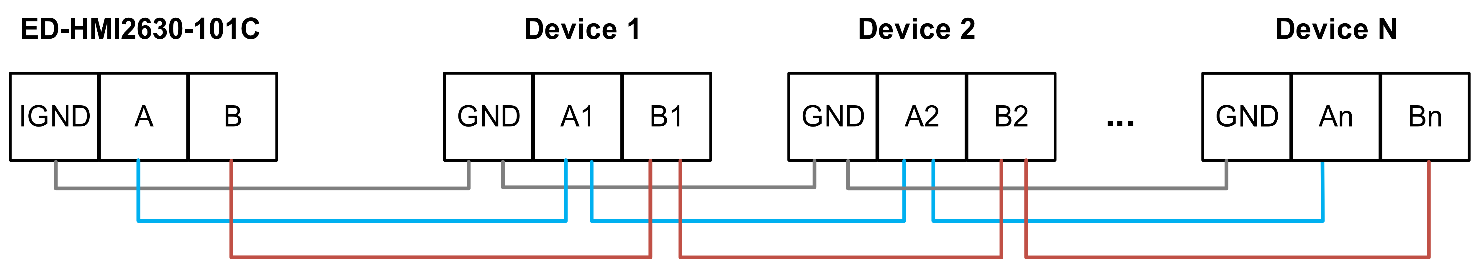
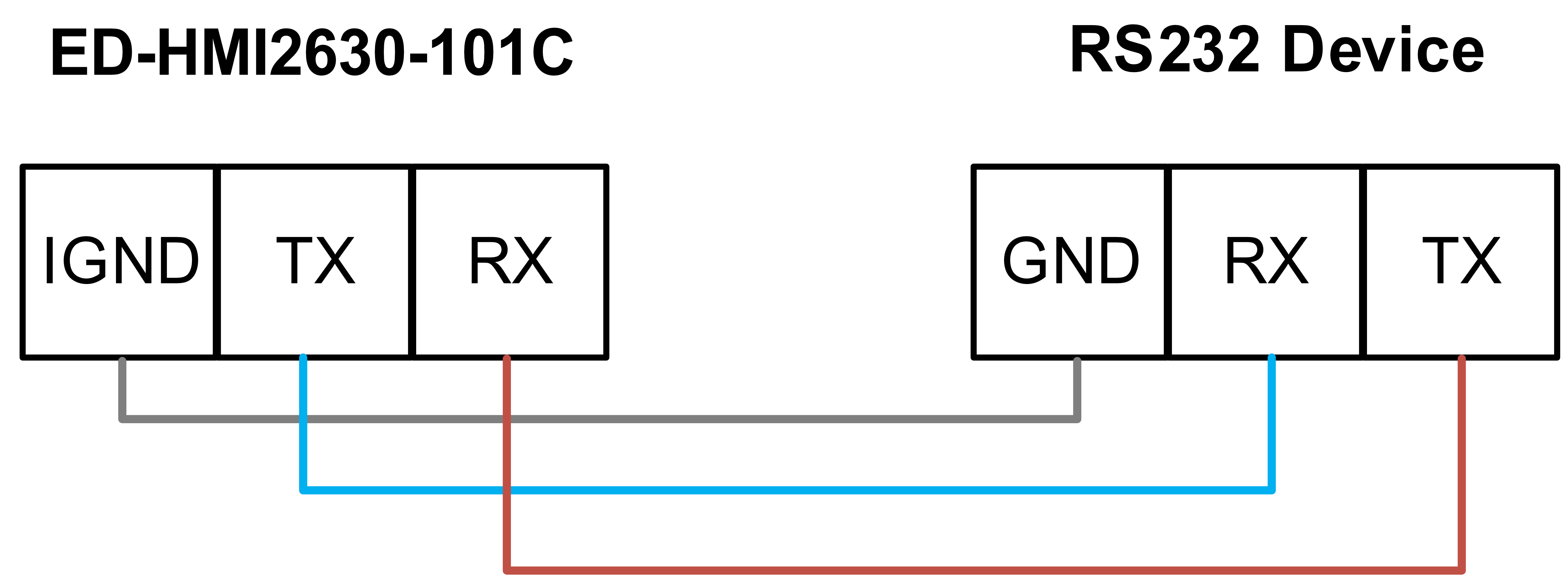
1.6.5 RS485/RS232 Interface
ED-HMI2630-101C includes 2~4 RS485 ports and 0~2 RS232 ports, Different product models correspond to different numbers of RS485 and RS232 ports:
- ED-HMI2632-101C:2 x RS485, 2 x RS232
- ED-HMI2633-101C:3 x RS485, 1 x RS232
- ED-HMI2634-101C:4 x RS485(without RS232)
The silkscreen of RS485 single port is ‘IGND/A/B’, the silkscreen of RS232 single port is ‘IGND/TX/RX’, and 3.5mm pitch phoenix terminals .
Pin Definition
Terminal pins are defined as follows:
 | Pin ID | Pin Name |
|---|---|---|
| 1 | RS485-2_B | |
| 2 | RS485-4_B | |
| 3 | RS485-2_A | |
| 4 | RS485-4_A | |
| 5 | GND | |
| 6 | GND | |
| 7 | RS232-1_RX or RS485-1_B | |
| 8 | RS232-3_RX or RS485-3_B | |
| 9 | RS232-1_TX or RS485-1_A | |
| 10 | RS232-3_TX or RS485-3_A | |
| 11 | GND | |
| 12 | GND |
The pin names of the RS485 port corresponding to CM4 are as follows:
| Signal | CM4 GPIO Name | CM4 Pin Out |
|---|---|---|
| RS485-2_B | GPIO13 | UART5_RXD |
| RS485-4_B | GPIO9 | UART4_RXD |
| RS485-2_A | GPIO12 | UART5_TXD |
| RS485-4_A | GPIO8 | UART4_TXD |
| RS232-1_RX or RS485-1_B | GPIO5 | UART3_RXD |
| RS232-3_RX or RS485-3_B | GPIO1 | UART2_RXD |
| RS232-1_TX or RS485-1_A | GPIO4 | UART3_TXD |
| RS232-3_TX or RS485-3_A | GPIO0 | UART2_TXD |
Connecting Cables
The RS485 wiring schematic is as follows:
The RS232 wiring schematic is as follows:
RS485 terminal resistance configuration
ED-HMI2630-101C includes 2~4 RS485 ports, 120R jumper resistor is reserved between A and B of each RS485 line, plug in the jumper cap to enable the jumper resistor. The 120R termination resistor function is disabled when the jumper cap is not connected in the default state.
The locations of the 120Ω termination resistors for the 4 RS485 ports in the PCBA and the corresponding COM ports are shown in the table as follows.
| Location in PCBA | Corresponding COM ports | The specific location of the corresponding COM |
|---|---|---|
| J19 | COM3 | 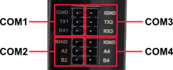 |
| J21 | COM1 | |
| J24 | COM4 | |
| J22 | COM2 |
1.6.6 DI Interface
ED-HMI2630-101C includes 8 DI ports, every 4 DI ports share one common terminal (called COM): X0, X2, X4 and X6 share COMX0; X1, X3, X5 and X7 share COMX1.
Pin Definition
Terminal pins are defined as follows:
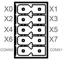 | Pin ID | Pin Name |
|---|---|---|
| 1 | X0 | |
| 2 | X1 | |
| 3 | X2 | |
| 4 | X3 | |
| 5 | X4 | |
| 6 | X5 | |
| 7 | X6 | |
| 8 | X7 | |
| 9 | COMX0 | |
| 10 | COMX1 |
Connecting Cables
The wiring schematic for the single DI port is shown as follows:
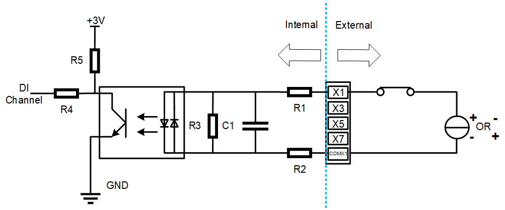
| Parameters | Instructions |
|---|---|
| Input Type | NPN and PNP |
| Isolation Protection | 5 kV |
| COM | Every 4 DI ports share one common pin (called COM): X0, X2, X4 and X6 share COMX0 X1, X3, X5 and X7 share COMX1 |
| DI to COM | ON state: 5~30 VDC OFF state: 0~2 VDC |
1.6.7 DO Interface
The ED-HMI2630-101C device includes 8 DO ports, every 4 DO ports share one common terminal (called COM): Y0, Y2, Y4 and Y6 share COMY0; Y1, Y3, Y5 and Y7 share COMY1.
Pin Definition
Terminal pins are defined as follows:
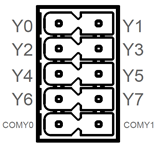 | Pin ID | Pin Name |
|---|---|---|
| 1 | Y0 | |
| 2 | Y1 | |
| 3 | Y2 | |
| 4 | Y3 | |
| 5 | Y4 | |
| 6 | Y5 | |
| 7 | Y6 | |
| 8 | Y7 | |
| 9 | COMY0 | |
| 10 | COMY1 |
Connecting Cables
The wiring schematic for the single DO port is shown as follows:
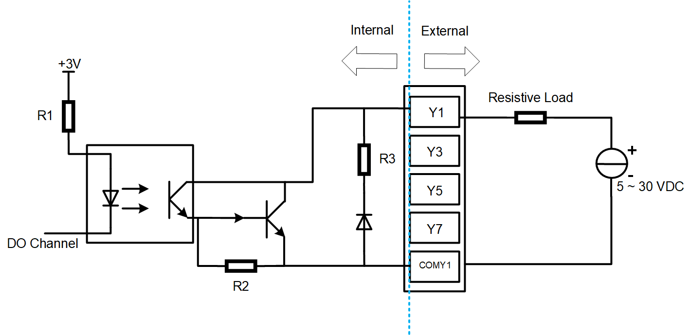
| Parameters | Instructions |
|---|---|
| Output Type | Transistor |
| Isolation Protection | 5 kV |
| COM | Every 4 DI ports share one common terminal (called COM): Y0, Y2, Y4 and Y6 share COMY0 Y1, Y3, Y5 and Y7 share COMY1 |
| Output | 5~30 VDC (24 VDC is recommended), maximum current is 1.5A (per channel) |
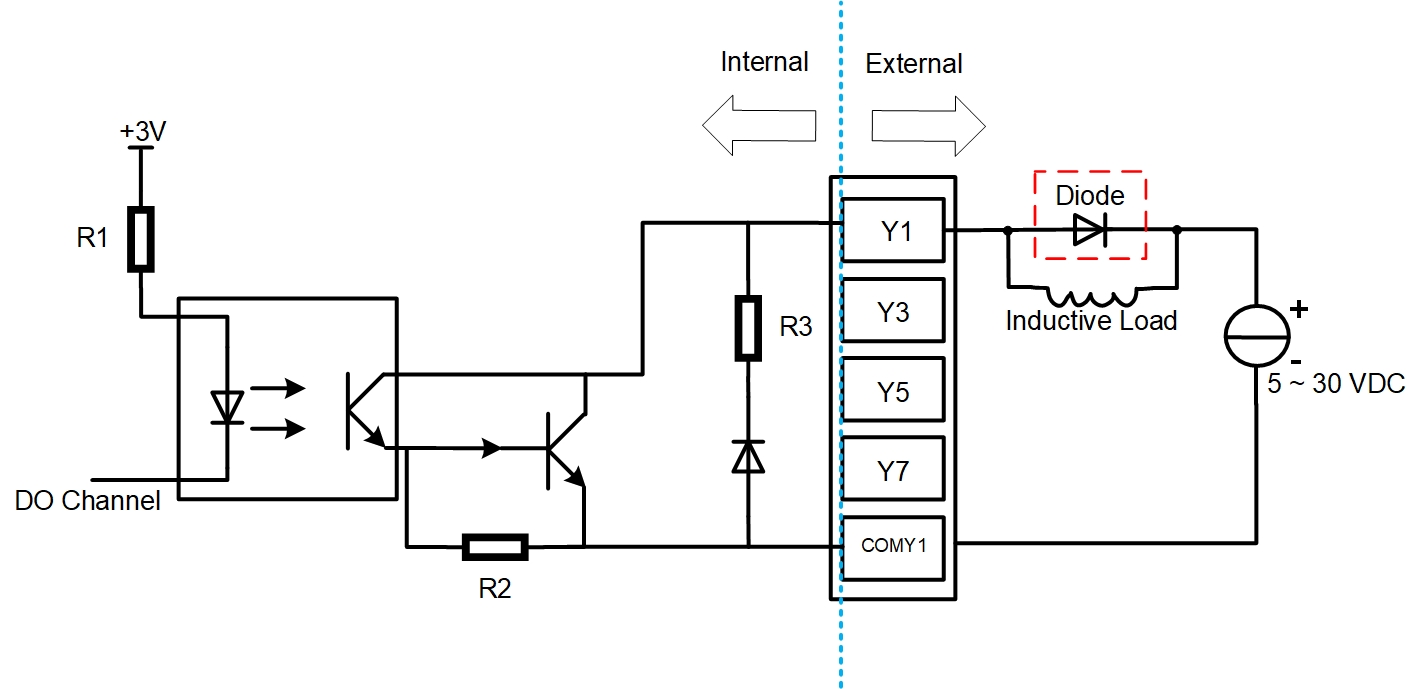
WARNING
If an inductive load is connected to the DO channel, it is recommended to add a Diode in the circuit (as shown in the figure below) for protection. Select an appropriate Diode based on the specifications of the inductive load.
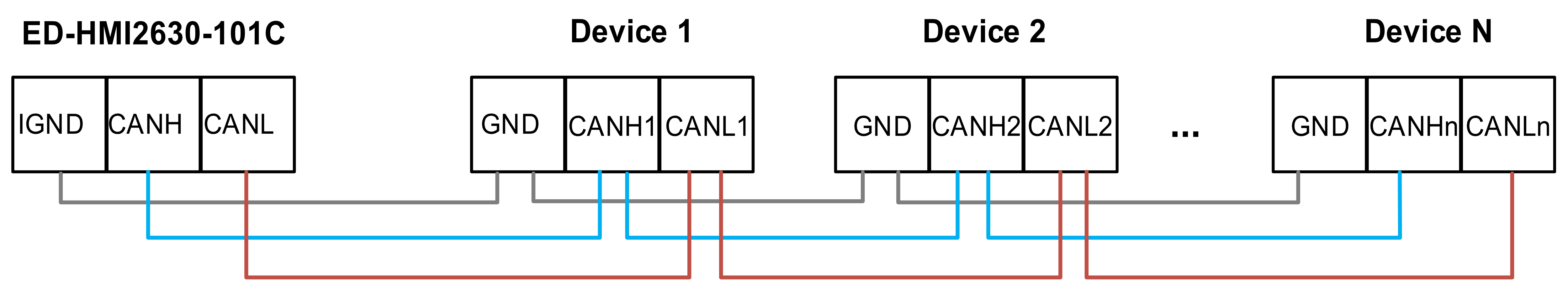
1.6.8 CAN Interface
The ED-HMI2630-101C includes 2 CAN ports.
Pin Definition
Terminal pins are defined as follows:
 | Pin ID | Pin Name |
|---|---|---|
| 1 | CANB0H | |
| 2 | CANB1H | |
| 3 | CANB0L | |
| 4 | CANB1L | |
| 5 | GND | |
| 6 | GND |
TIP
In the older version of the product, the silkscreen for the CAN interfaces were marked as "CAN0H/CAN0L/GND" and "CAN1H/CAN1L/GND".
Connecting Cables
The wiring schematic for the CAN ports is shown as follows:
1.6.9 1000M Ethernet Interface
ED-HMI2630-101C includes an adaptive 10/100/1000M Ethernet port, and the silkscreen is "  ". When accessing to network, it is recommended to use the network cable of Cat6 and above. The pins corresponding to the terminal are defined as follows:
1.6.10 100M Ethernet Interface
ED-HMI2630-101C includes an adaptive 10/100M Ethernet port, and the silkscreen is " ". When accessing to network, it is recommended to use the network cable of Cat6 and above. The pins corresponding to the terminal are defined as follows:
1.6.11 HDMI Interface
ED-HMI2630-101C includes one HDMI port, the silkscreen is "HDMI", The connector is type-A HDMI, which can connect to an HDMI display and supports up to 4Kp60.
1.6.12 USB 2.0 Interface
ED-HMI2630-101C includes 2 USB2.0 ports, the silkscreen is " ". The connector is type-A USB, which can connect to standard USB 2.0 peripherals and supports up to 480Mbps.
1.6.13 Micro USB Interface
ED-HMI2630-101C includes one Micro USB port, the silkscreen is "PROGRAMMING", and it can be connected to a PC to flash to eMMC of the device.
1.6.14 Antenna Interface (Optional)
ED-HMI2630-101C includes 2 SMA antenna connectors, the silkscreens are "4G" and "Wi-Fi/BT" and they can be connected to the 4G antenna and Wi-Fi/BT antenna.
TIP
The number of antenna port is related to the actual model selected by the user, and only 2 antenna ports are included here as an example.
1.7 Supercapacitor (Optional)
The ED-HMI2630-101C supports an optional supercapacitor backup power module, featuring a comprehensive safe shutdown protection mechanism.
- In the event of an unexpected power failure when the supercapacitor is fully charged, the system will automatically turn off the screen backlight and reduce the CPU frequency to save power. The device continues to operate in a low-power state until the capacitor's charge is depleted, after which it automatically shuts down safely. This effectively prevents operational interruptions and data loss.
- The device provides user-customizable emergency scripts, allowing for the pre-configuration of critical data saving, backup, or other emergency procedures. At the moment of power loss, the system will automatically execute the preset scripts to ensure critical operations are completed, enabling a composed response to sudden power outages.
TIP
- For specific operations on customizing supercapacitor-related parameters, please refer to AN18 Supercapacitor Usage Guide.
- The supercapacitor requires the device to be powered on for at least 5 minutes to fully charge, and normal functionality is only guaranteed when it is fully charged.