4 Software Operation Guide
4.1 Button
ED-GWL2010 contains a user-defined button inside the device, which is connected to the GPIO23 pin of CPU. It is at a high level by default. When the button is pressed, the pin is at a low level.
You can use the raspi-gpio command to test.
- Query the GPIO23 pin when the button is not pressed.
raspi-gpio get 23
GPIO 23: level=1 fsel=0 func=INPUT
level of 1 indicates that the GPIO23 pin is high.
- Query the GPIO23 pin When the button is pressed.
raspi-gpio get 23
GPIO 23: level=0 fsel=0 func=INPUT
level of 0 indicates that the GPIO23 pin is low.
4.2 LED Indication
ED-GWL2010 includes an RGB 3-color LED indicator, and the corresponding GPIO pins are as follows:
| RGB LED PIN | GPIO |
|---|---|
| Blue | GPIO16 |
| Green | GPIO20 |
| Red | GPIO21 |
When the GPIO output is low, the corresponding LED is valid.
You can use the raspi-gpio command to operate, and the configuration parameter is op, which means output setting, dl setting pin is low level, and dh setting pin is high level.
The LED is displayed in blue.
sudo raspi-gpio set 16 op dl
sudo raspi-gpio set 20 op dh
sudo raspi-gpio set 21 op dh
The LED is displayed in green.
sudo raspi-gpio set 16 op dh
sudo raspi-gpio set 20 op dl
sudo raspi-gpio set 21 op dh
The LED is displayed in red.
sudo raspi-gpio set 16 op dh
sudo raspi-gpio set 20 op dh
sudo raspi-gpio set 21 op dl
The LED is displayed in yellow.
sudo raspi-gpio set 16 op dh
sudo raspi-gpio set 20 op dl
sudo raspi-gpio set 21 op dl
4.3 Ethernet Configuration
ED-GWL2010 includes one adaptive 10/100/1000M Ethernet interface.
The official OS of Raspberry Pi uses dhcpcd as the network management tool by default.
Static IP can be set by modifying “/etc/dhcpcd.conf”. For example, eth0 can be set, and users can set wlan0 and other network interfaces according to their different needs.
interface eth0
static ip_address=192.168.0.10/24
static routers=192.168.0.1
static domain_name_servers=192.168.0.1 8.8.8.8 fd51:42f8:caae:d92e::1
4.4 WIFI
ED-GWL2010 supports 2.4GHz&5GHz IEEE 802.11 b/g/n dual-band Wi-Fi.
The official OS of Raspberry Pi uses dhcpcd as the network management tool by default.
- Execute “
sudo raspi-config” command. - Choose 1 System Options.
- Choose S1 Wireless LAN.
- Select your country in the “Select the country in which the pi is to be used” window, and then select OK. This prompt only appears when setting up Wi-Fi for the first time.
- Please enter SSID,input WIFI SSID name.
- Please enter passphrase. Leave it empty if none, input password and then restart the device。
4.5 Bluetooth
ED-GWL2010 supports Bluetooth 5.0 and Bluetooth Low Energy (BLE). The Bluetooth function is enabled by default.
Bluetoothctl can be used to scan, pair and connect Bluetooth devices. Please refer to the ArchLinux-Wiki-Bluetooth guide to configure and use Bluetooth.
4.5.1 Basic Configuration Commands
| Command | Function Description |
|---|---|
| bluetoothctl scan on | Enable Bluetooth scanning |
| bluetoothctl scan off | Disable Bluetooth scanning |
| bluetoothctl discoverable on | Enable Bluetooth discovery (which can be discovered by the other party) |
| bluetoothctl discoverable off | Disable Bluetooth discovery |
| bluetoothctl trust device MAC | Trust device |
| bluetoothctl connect device MAC | Connect device |
| bluetoothctl disconnect device MAC | Disconnect device |
4.5.2 Configuration Example
This chapter introduces how to configure Bluetooth through a configuration example.
Preparation:
The Bluetooth to be paired has been enabled and its name has been determined.
Steps:
- Enter the Bluetooth view.
sudo bluetoothctl
- Enable bluetooth.
power on
- Scan Bluetooth device.
scan on
Returned display information:
Discovery started
[CHG] Controller B8:27:EB:85:04:8B Discovering: yes
[NEW] Device 4A:39:CF:30:B3:11 4A-39-CF-30-B3-11
- Find the name of the turned-on Bluetooth device.
devices
Returned display information:
Device 6A:7F:60:69:8B:79 6A-7F-60-69-8B-79
Device 67:64:5A:A3:2C:A2 67-64-5A-A3-2C-A2
Device 56:6A:59:B0:1C:D1 Lefun
Device 34:12:F9:91:FF:68 test
- Pairing target devices.
pair 34:12:F9:91:FF:68
34:12:F9:91:FF:68 is target device’s device_MAC
Returned display information:
Attempting to pair with 34:12:F9:91:FF:68
[CHG] Device 34:12:F9:91:FF:68 ServicesResolved: yes
[CHG] Device 34:12:F9:91:FF:68 Paired: yes
Pairing successful
TIP:
The Bluetooth device to be connected also needs to confirm the pairing request, otherwise the pairing will fail.
- Add as trusted device.
trust 34:12:F9:91:FF:68
34:12:F9:91:FF:68 is target device’s device_MAC
Returned display information:
[CHG] Device 34:12:F9:91:FF:68 Trusted: yes
Changing 34:12:F9:91:FF:68 trust succeeded
4.6 LoRaWAN
The ED-GWL2110 supports LoRaWAN and the open-source service platform ChirpStack. The following section details the specific installation and configuration procedures.
TIP
Only the US915 LoRa gateway module is used as an example for this introduction.
4.6.1 Chirpstack Client
- The device comes pre-installed with firmware packages, LoRa module packages, and ChirpStack software packages. Verify using:
dpkg -l | grep ed-
- For OS reinstallation, refer to the Installing OS section.
4.6.2 Configuration File Modifications
4.6.2.1 Modify JSON Configuration File
- Start
ed-lora.service:
sudo systemctl enable --now ed-lora.service
- Get the configuration file path:
systemctl status ed-lora.service
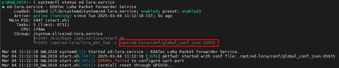
- Open the configuration file:
sudo nano /opt/ed-lora/conf/global_conf.json.US915
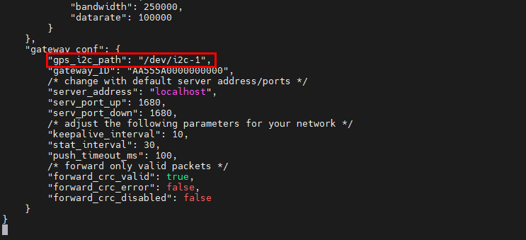
- Delete
"gps_i2c_path": "/dev/i2c-1"at the bottom.
4.6.2.2 Modify ChirpStack Configuration
- Open the configuration file.
sudo nano /etc/chirpstack-gateway-bridge/chirpstack-gateway-bridge.toml
Make the following changes:
udp_bind = "0.0.0.0:1700"→udp_bind = "0.0.0.0:1680"- Add gateway model prefix:
event_topic_template="gateway/{{ .GatewayID }}/event/{{ .EventType }}"→event_topic_template="us915_0/gateway/{{ .GatewayID }}/event/{{ .EventType }}".command_topic_template="gateway/{{ .GatewayID }}/command/#"→command_topic_template="us915_0/gateway/{{ .GatewayID }}/command/#".
TIP
For EU868/CN470 modules, replace
us915_0witheu868_0orcn470_10.Restart services:
sudo systemctl daemon-reload
sudo systemctl restart chirpstack-gateway-bridge.service ed-lora.service
4.6.3 ChirpStack Server Deployment
The ChirpStack server can be deployed either on the current device or on another device within the same LAN. This documentation uses deployment on the current device as an example. (If deploying on another LAN device, modify the udp_bind value from 0.0.0.0 to that device's IP address in Section 3.10.2.2 Modify ChirpStack Configuration).
- Install dependencies:
sudo apt install docker-compose -y
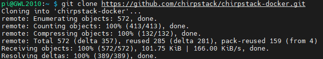
- Clone the repository:
git clone https://github.com/chirpstack/chirpstack-docker.git
- Modify configuration:
cd chirpstack-docker
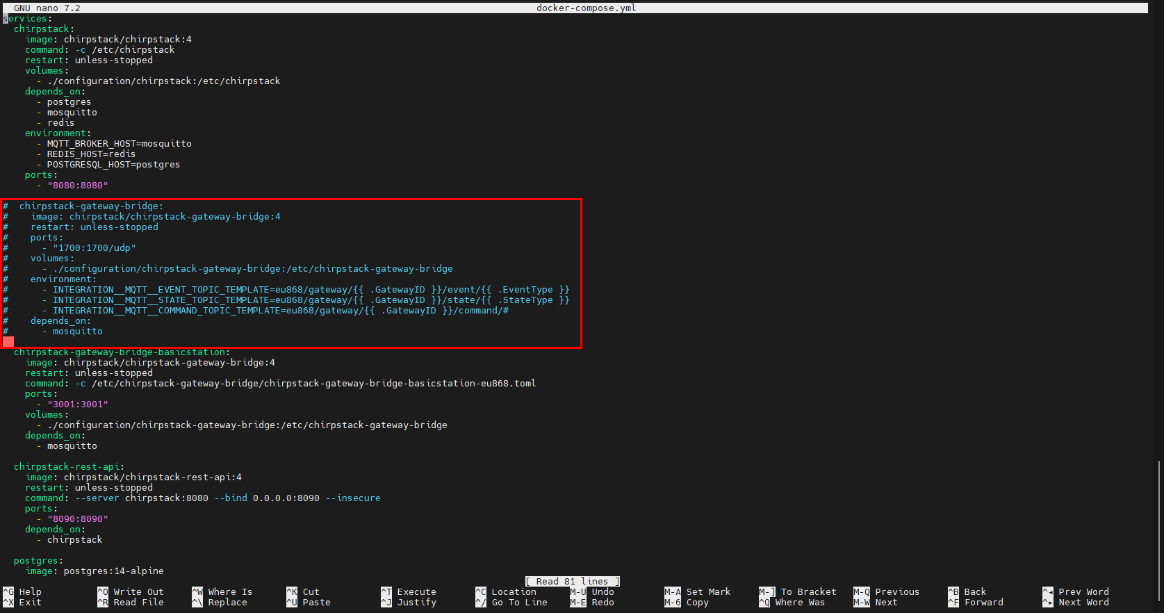
nano docker-compose.yml
- Comment out the
chirpstack-gateway-bridgesection.
services:
  chirpstack:
    image: chirpstack/chirpstack:4
    command: -c /etc/chirpstack
    restart: unless-stopped
    volumes:
      - ./configuration/chirpstack:/etc/chirpstack
    depends_on:
      - postgres
      - mosquitto
      - redis
    environment:
      - MQTT_BROKER_HOST=mosquitto
      - REDIS_HOST=redis
      - POSTGRESQL_HOST=postgres
    ports:
      - "8080:8080"

#  chirpstack-gateway-bridge:
#    image: chirpstack/chirpstack-gateway-bridge:4
#    restart: unless-stopped
#    ports:
#      - "1700:1700/udp"
#    volumes:
#      - ./configuration/chirpstack-gateway-bridge:/etc/chirpstack-gateway-bridge
#    environment:
#      - INTEGRATION__MQTT__EVENT_TOPIC_TEMPLATE=eu868/gateway/{{ .GatewayID }}/event/{{ .EventType }}
#      - INTEGRATION__MQTT__STATE_TOPIC_TEMPLATE=eu868/gateway/{{ .GatewayID }}/state/{{ .StateType }}
#      - INTEGRATION__MQTT__COMMAND_TOPIC_TEMPLATE=eu868/gateway/{{ .GatewayID }}/command/#
#    depends_on:
#      - mosquitto

  chirpstack-gateway-bridge-basicstation:
    image: chirpstack/chirpstack-gateway-bridge:4
    restart: unless-stopped
    command: -c /etc/chirpstack-gateway-bridge/chirpstack-gateway-bridge-basicstation-eu868.toml
    ports:
      - "3001:3001"
    volumes:
      - ./configuration/chirpstack-gateway-bridge:/etc/chirpstack-gateway-bridge
    depends_on:
      - mosquitto

  chirpstack-rest-api:
    image: chirpstack/chirpstack-rest-api:4
    restart: unless-stopped
    command: --server chirpstack:8080 --bind 0.0.0.0:8090 --insecure
    ports:
      - "8090:8090"
    depends_on:
      - chirpstack

  postgres:
    image: postgres:14-alpine
    restart: unless-stopped
    volumes:
      - ./configuration/postgresql/initdb:/docker-entrypoint-initdb.d
      - postgresqldata:/var/lib/postgresql/data
    environment:
      - POSTGRES_USER=chirpstack
      - POSTGRES_PASSWORD=chirpstack
      - POSTGRES_DB=chirpstack

  redis:
    image: redis:7-alpine
    restart: unless-stopped
    command: redis-server --save 300 1 --save 60 100 --appendonly no
    volumes:
      - redisdata:/data

  mosquitto:
    image: eclipse-mosquitto:2
    restart: unless-stopped
    ports:
      - "1883:1883"
    volumes:
      - ./configuration/mosquitto/config/:/mosquitto/config/

volumes:
  postgresqldata:
  redisdata:
TIP
Customize MQTT service settings in the mosquitto section.
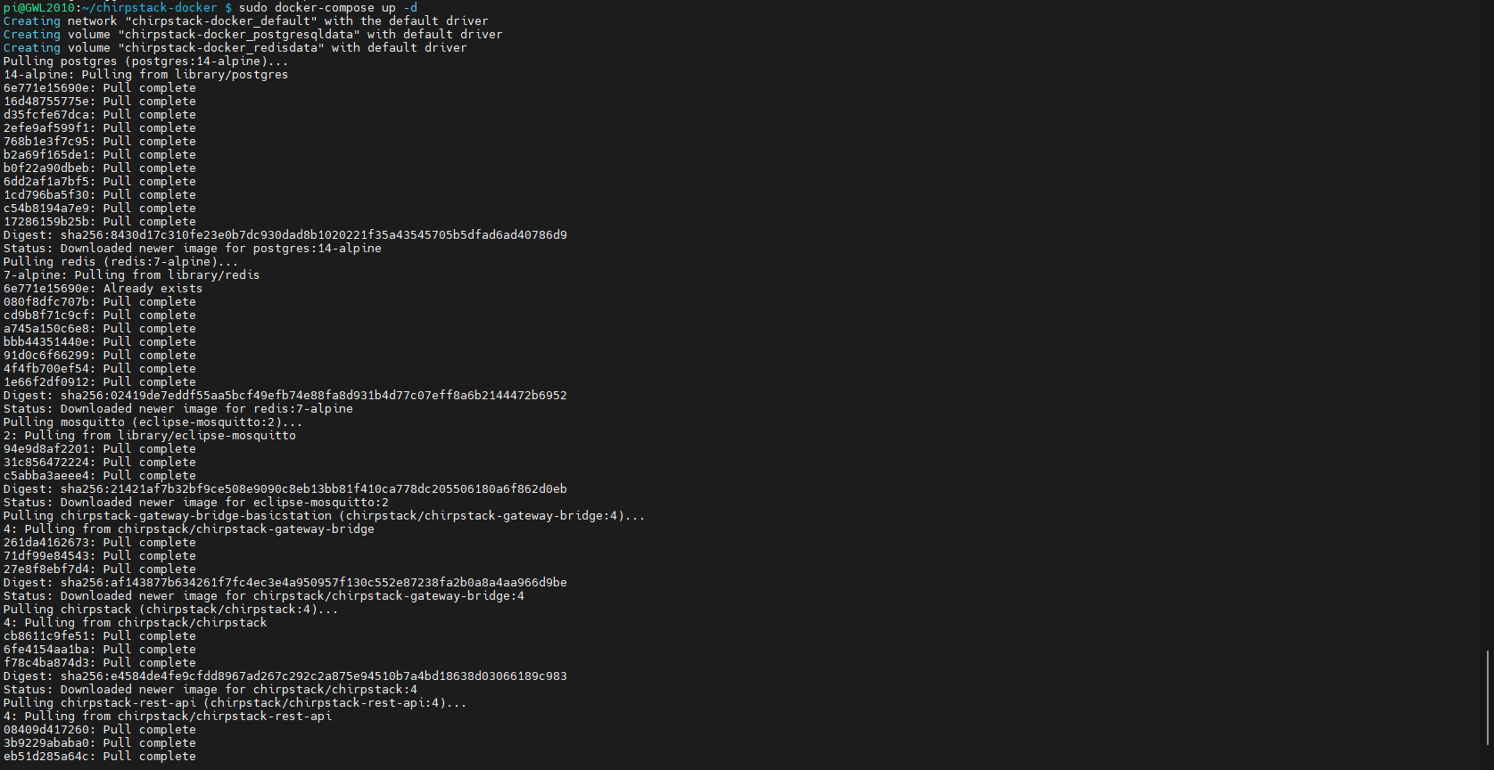
4.6.4 Start ChirpStack Server
Execute the following command on the device where the ChirpStack server is deployed to start the ChirpStack server.
sudo docker-compose up -d
4.6.5 ChirpStack Web Interface Operations
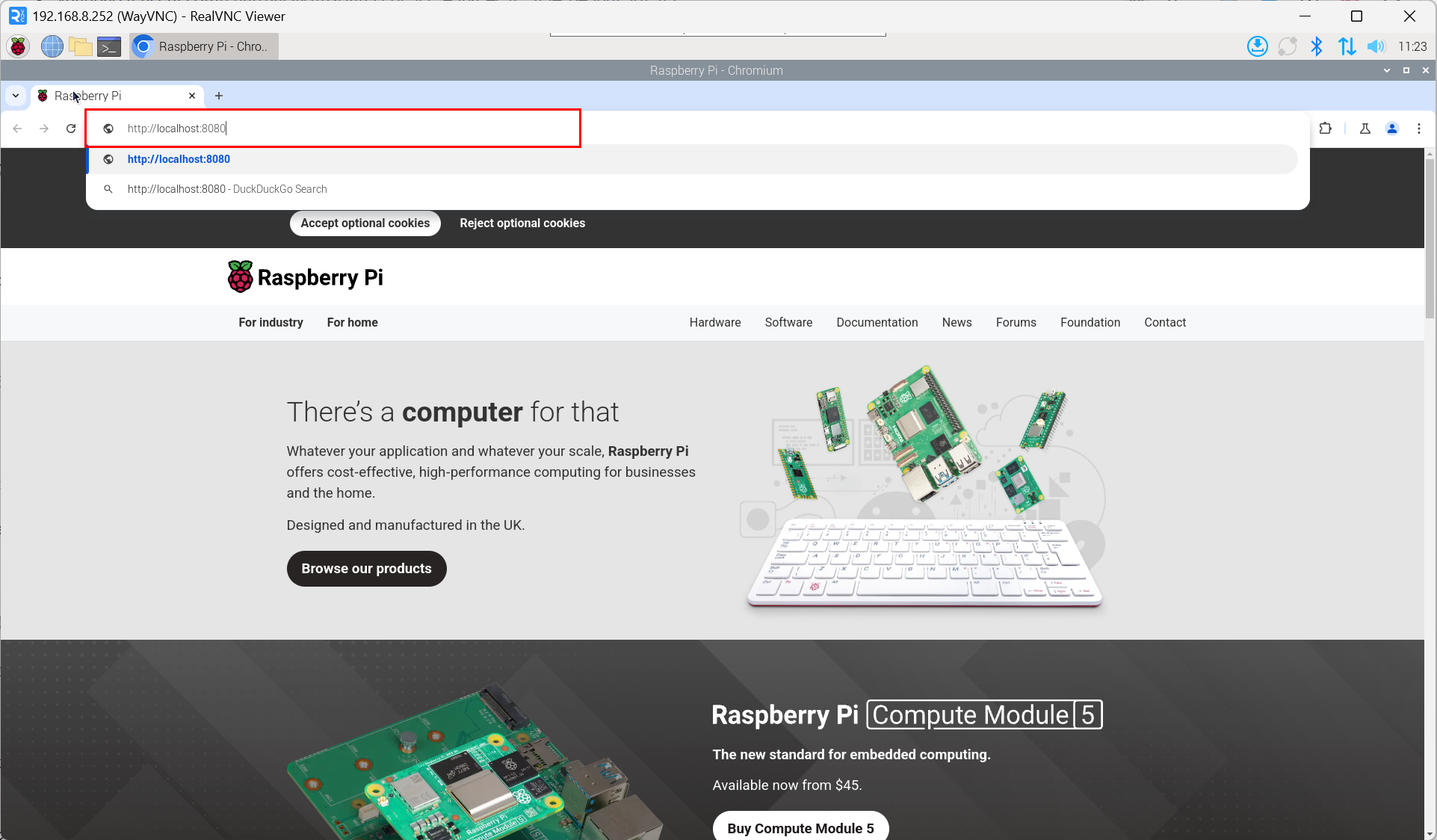
4.6.5.1 Access Web Interface
- Access via browser:
http://<server_ip>:8080.
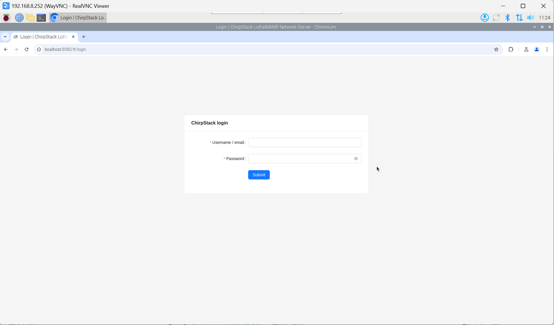
- Enter the username and password on the login interface.
TIP
The default username is admin, and the default password is admin.
4.6.5.2 Obtain Gateway ID
- Check service status:
systemctl status ed-lora.service
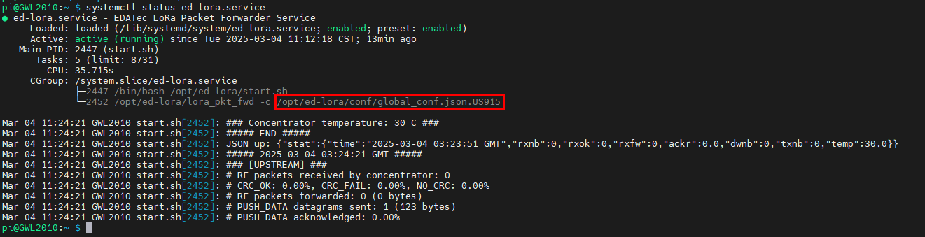
- Extract Gateway ID:
cat /opt/ed-lora/conf/global_conf.json.US915 | grep gateway

TIP
When adding a LoRa gateway on the ChirpStack server side, you need to provide the corresponding Gateway ID.
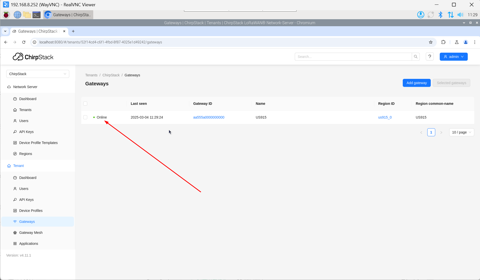
4.6.5.3 Add LoRa Gateway
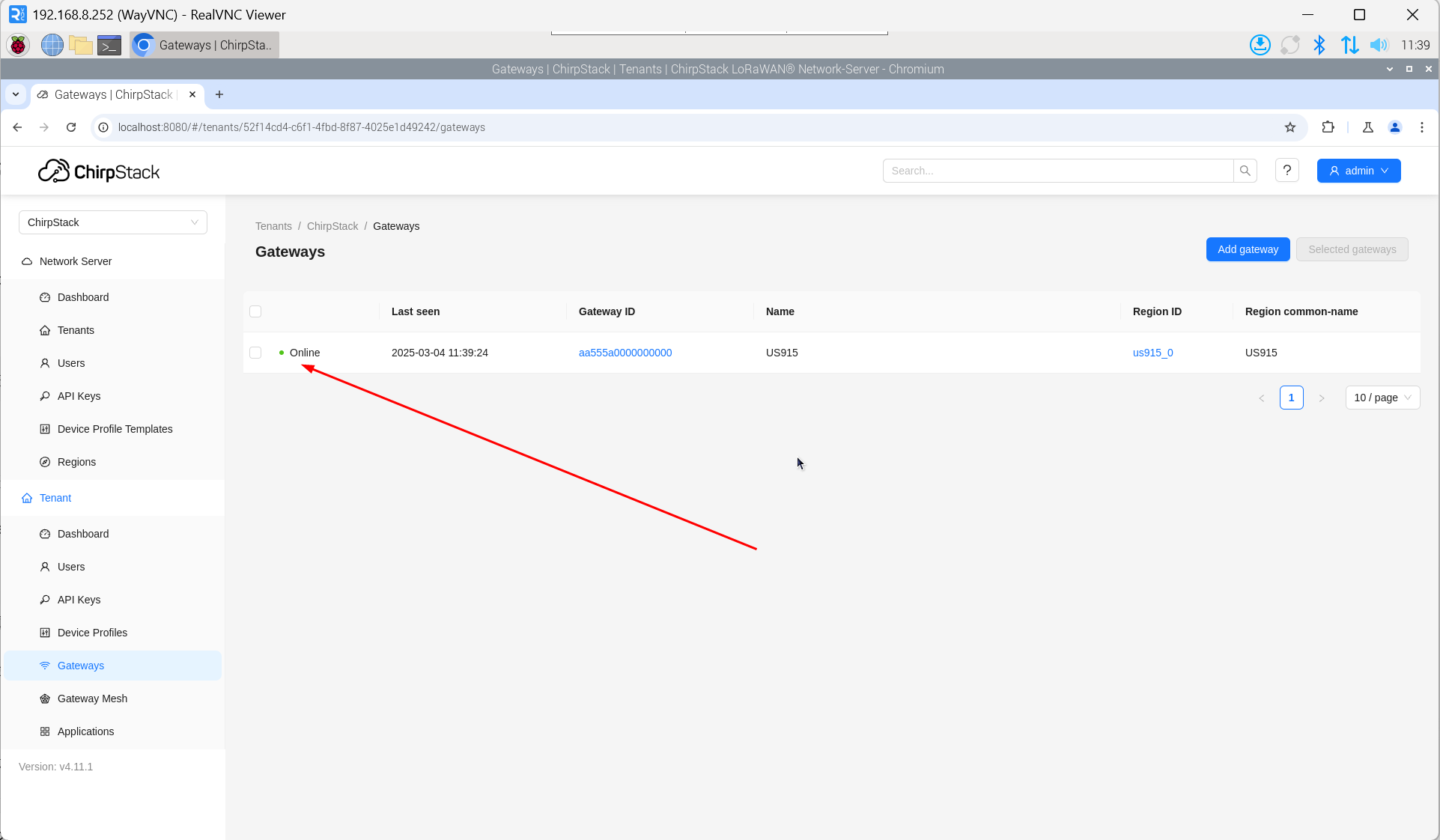
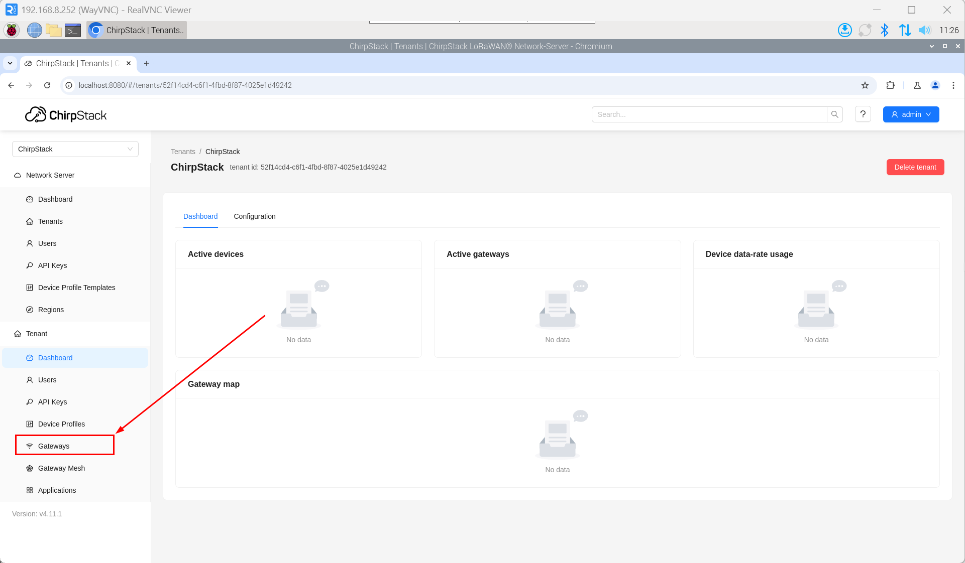
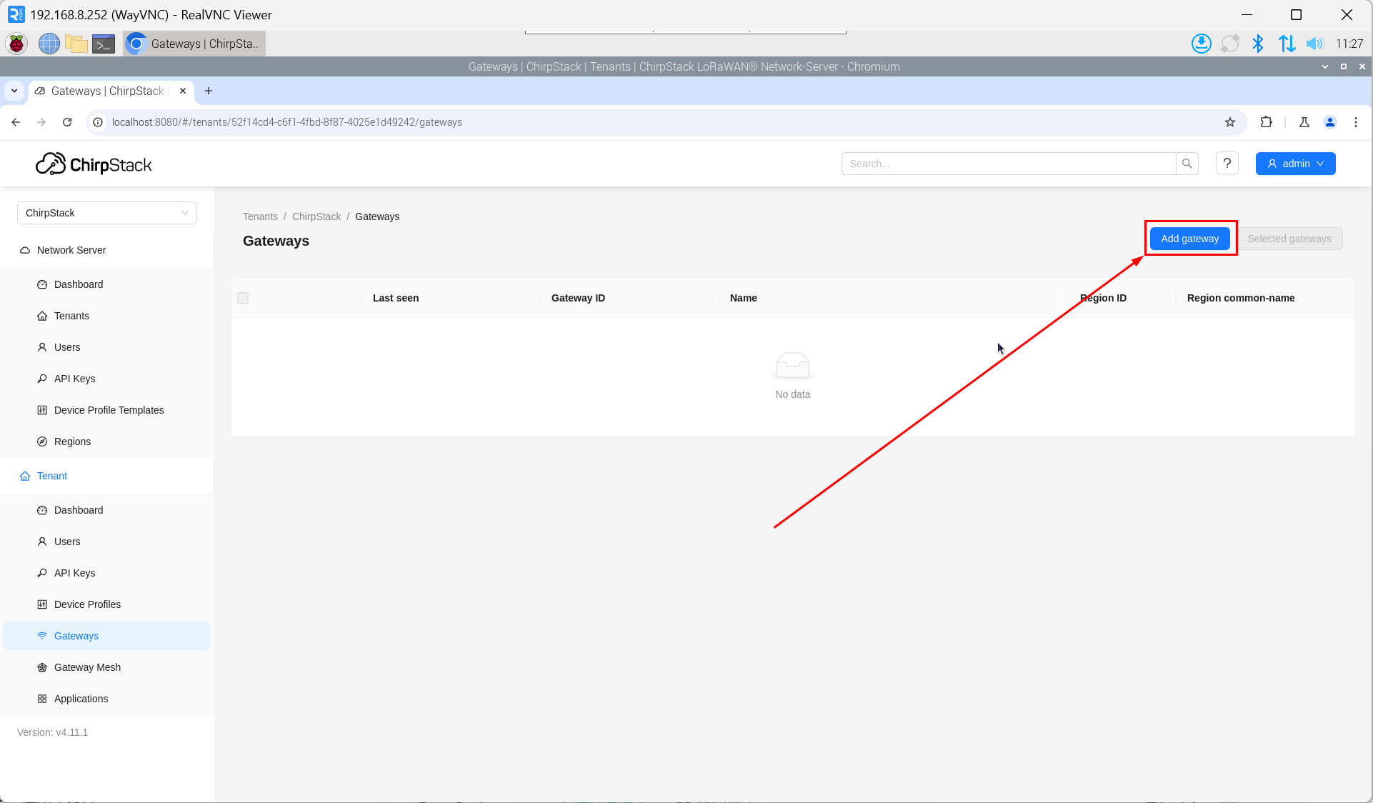
- Open the ChirpStack management interface in a PC browser, then click "Gateway" → "Add gateway".
- Click "add".
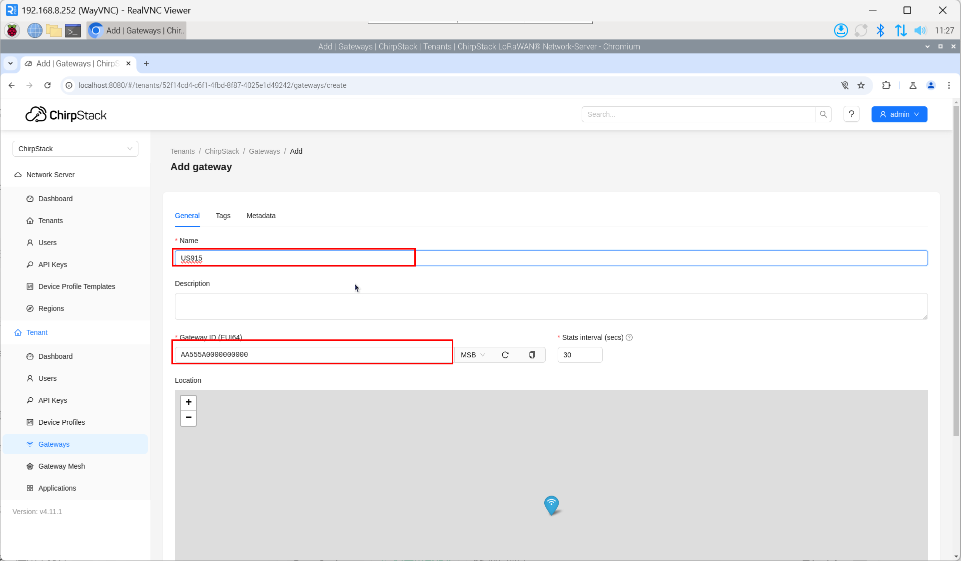
- Enter the corresponding Gateway ID for your device, set the Name, then click "Submit". If the network connection is properly configured, the added gateway will transition to an Online status momentarily.
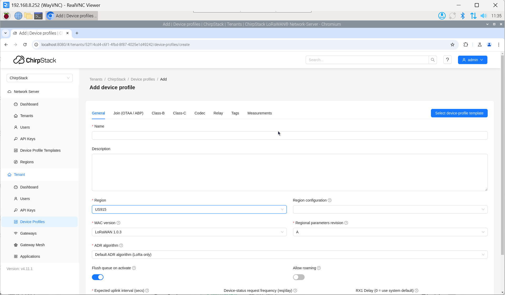
4.6.5.4 Add Device Profile
Click "Device Profile" → "Add device profile" to supplement device information.
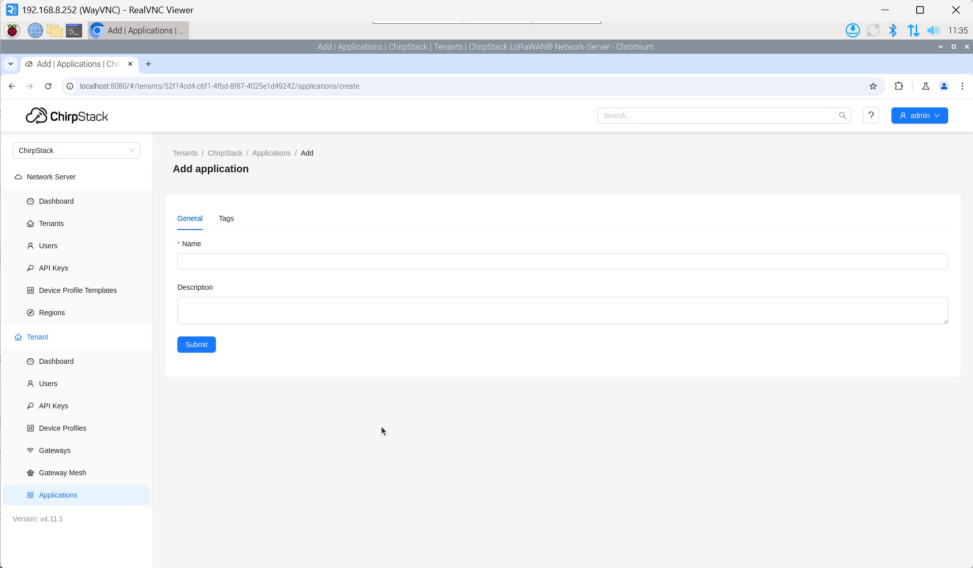
4.6.5.5 Add Application
Click "Applications" → "Add application".
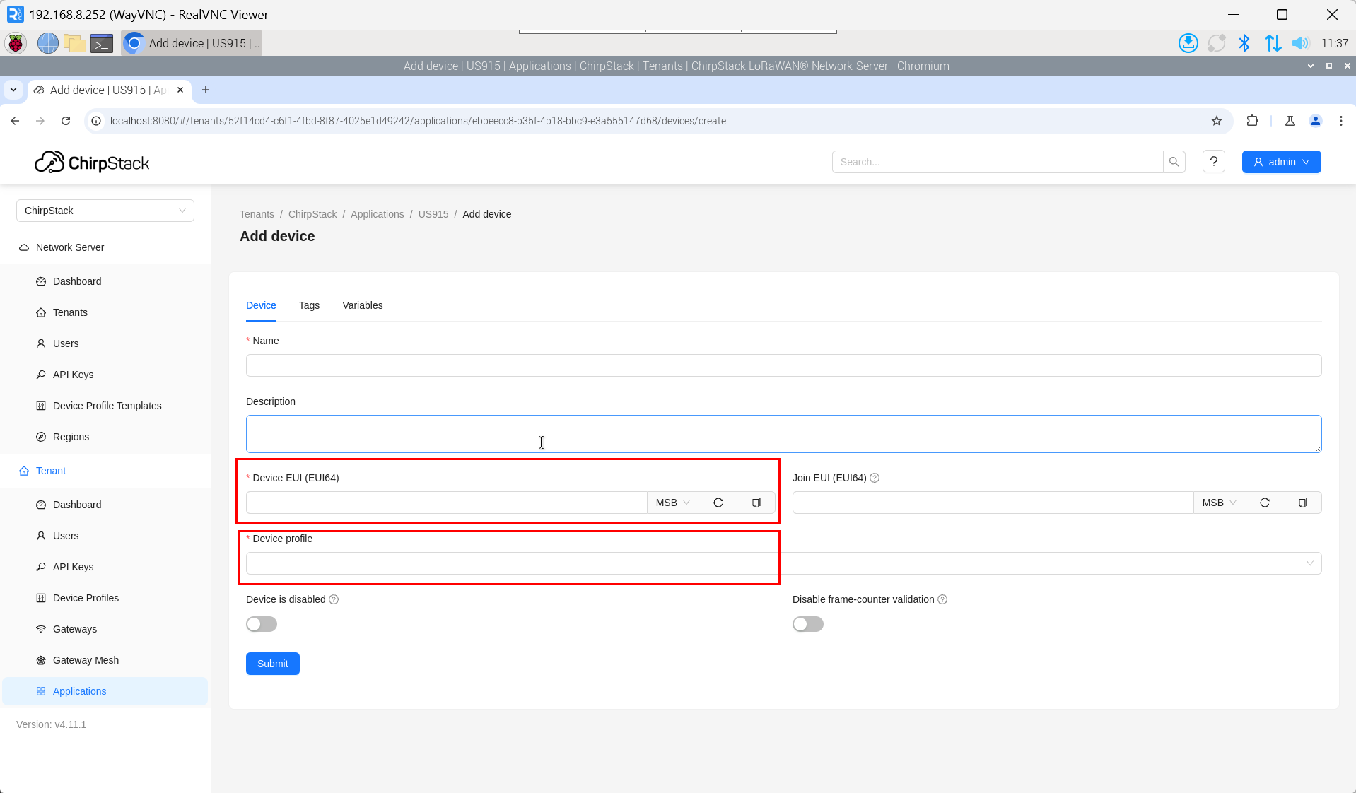
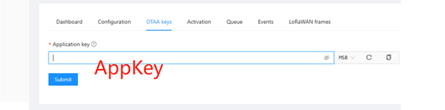
4.6.5.6 Add Device
The DevEUI and AppKey for LoRa end-device products are both provided by the LoRa device manufacturer.
- Click "Application" → "your application" → "Add device" to add the LoRa end-device.
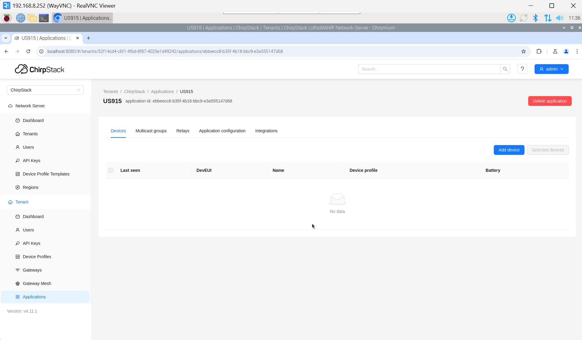
- After a few minutes, the device will appear in online status.