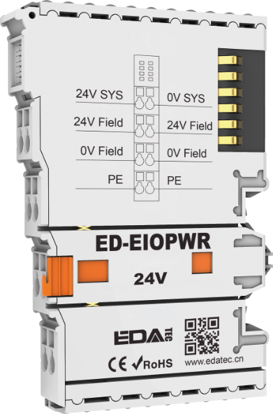
- Power expansion supply
- Input DC 24V system power
- DC 5V power expansion
- Plug-in construction, DIN-rail installation
- PT removable terminal block for screwless wiring
|
| Power Supply |
|---|
| Input Voltage | DC 24V (±20%) |
| Bus Output Voltage | DC 5V (±5%) |
| Bus Output Current | 2A (Max) |
| Protection Parameter |
|---|
| System Isolation Voltage | AC500V |
| Reverse Polarity Protection | Support |
| Overcurrent Protection | System power: support
I/O power: not support |
| Overvoltage Protection | Support |
| Mechanical Characteristics |
|---|
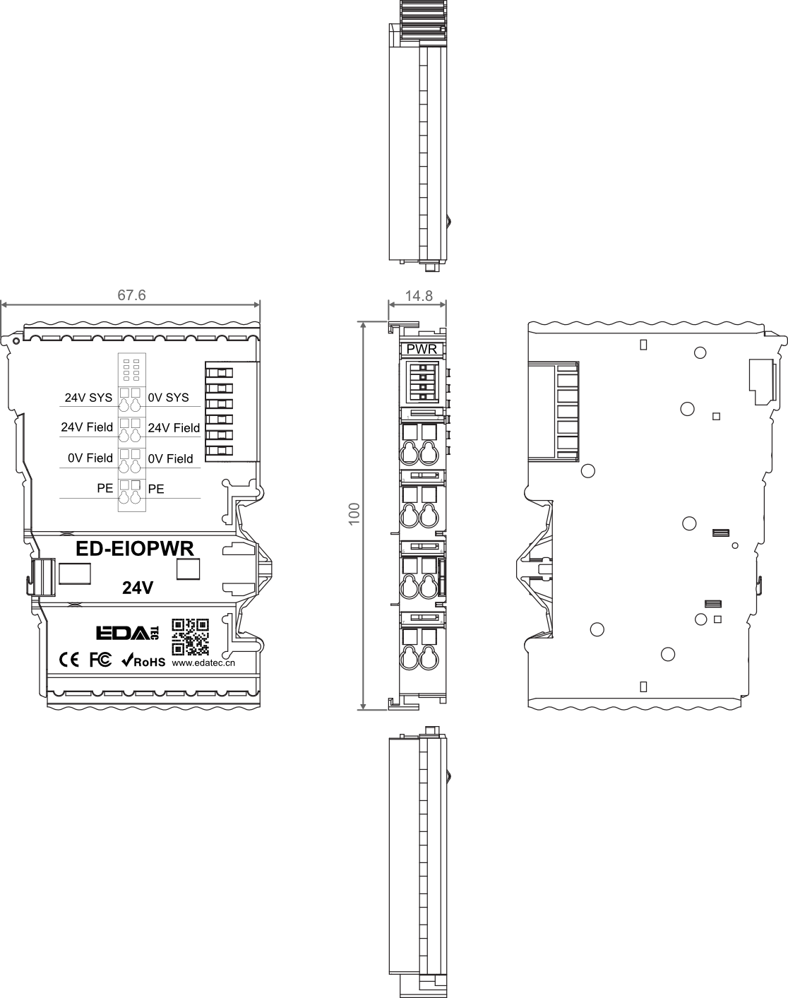
| Dimensions | 100mm x 67.6mm x 14.8 mm |
| Weight | About 51g |
| Wiring Specifications | 0.2mm² ~ 1.5mm² |
| Wiring Method | Screwless |
| Installation | DIN-rail installation |
| Environmental & Regulatory |
|---|
| Operating Temperature | -10℃ ~ 55℃ |
| Storage Temperature | -20℃ ~ 85℃ |
| Ambient Humidity | 5% ~ 95% (non-condensing) |
| Air Pressure | ≥ 795 hPa (altitude ≤ 2000 m), compliant with IEC 61131-2 |
| Overvoltage Categories | I |
| Certifications | CE and RoHS |
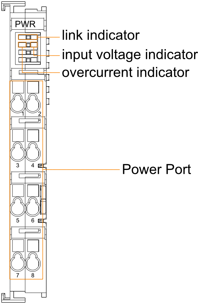
| System Power Indicator |
|---|
| Link | 1 x green link indicator, using to see if the connection of common terminal is normal. |
| Input Voltage | 1 x green input voltage indicator, using to see if the input voltage is normal. |
| Overcurrent | 1 x red overcurrent indicator, using to see if the coupler exceeds the maximum operating current. |
| Power Port |
|---|
| Pin No. | Description | Pin No. | Description |
| 1 | 24V SYS | 2 | 24V SYS |
| 3 | 24V Field | 4 | 24V Field |
| 5 | 0V Field | 6 | 0V Field |
| 7 | PE | 8 | PE |
Unit: mm
| Model | Description |
|---|
| ED-EIOPWR | Power Expansion Supply Module |
| Model | Description |
|---|
| ED-PLC2010 | EtherCAT Master based on CODESYS |
| ED-EIOBRG-EC | EtherCAT Coupler |
- 1 x Power Expansion Supply Module
TIP
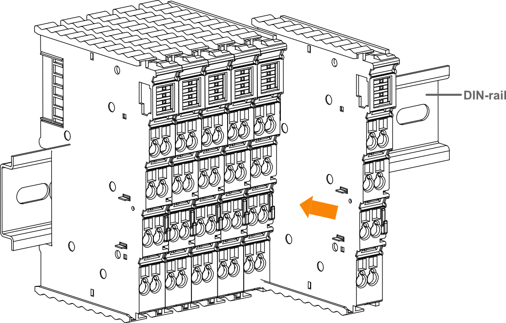
- DIN-rail is not included in the box, the following is intended as an installation illustration only.
- Before you start installing, please turn off the power to the module.
- If you encounter a situation where the module cannot be installed, please do not force the installation to avoid damaging the module.
Steps
The following is an example of the installation of an 8-terminal module only.
- Align the notches in the I/O module.

- Secure the I/O module to the DIN-rail by pushing the I/O module in the direction of the arrow onto the DIN snap pin.
TIP
- Before you start installing, please turn off the power and disconnect the cable to the module.
- If you encounter a situation where the module cannot be installed, please do not force the installation to avoid damaging the module.
Steps
The following is an example of the dismantling of an 8-terminal module only.
- Hold the snap pin of the I/O module by hand and then pull it out in the direction of the arrow to disengage the module from the DIN-rail.