1 Hardware Manual
This chapter provides hardware information on the EtherCAT coupler, digital input/output module, analogue input/output module, temperature input module, high-speed counter module and bus end cover.
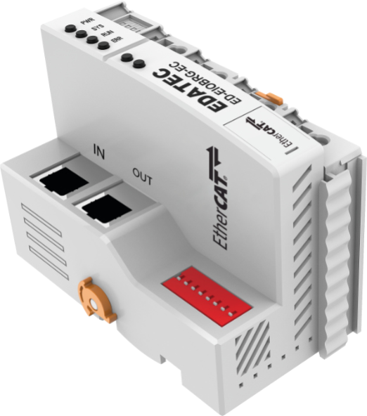
1.1 EtherCAT Coupler (ED-EIOBRG-EC)
This section describes the product overview, packing list, appearance, buttons, indicators, cable connections and interfaces of the ED-EIOBRG-EC.
1.1.1 Overview
The ED-EIOBRG-EC is an EtherCAT coupler that provides an EtherCAT communication interface for connecting EtherCAT slave hardware devices. The ED-EIOBRG-EC has a transmission distance of up to 100 m and supports the extension of up to 32 I/O modules and up to 65,534 network nodes. The ED-EIOBRG-EC can be used as a connection node to connect multiple EtherCAT slaves to an EtherCAT network to meet the requirements of different application scenarios.
1.1.2 Packing List
1 x EtherCAT Coupler
1.1.3 Appearance
Introducing the functions and definitions of interfaces on each panel.
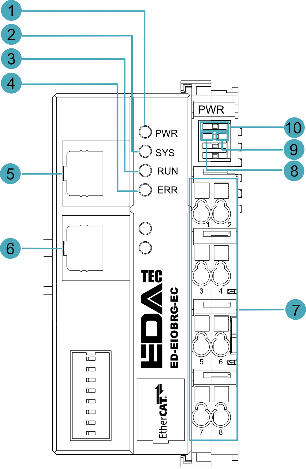
| NO. | Function Definition |
|---|---|
| 1 | 1 x EtherCAT Coupler power indicator, green, using for viewing the connection status of the coupler system power supply. |
| 2 | 1 x System tip indicator, green, using for viewing the operational status of the coupler. |
| 3 | 1 x Running indicator, green, using for viewing the running status of the coupler. |
| 4 | 1 x Fault indicator, red, using to see if the coupler is malfunctioning. |
| 5 | 1 x EtherCAT input port for access to the EtherCAT network, supporting to connect EtherCAT masters or the EtherCAT OUT port of other EtherCAT slaves. |
| 6 | 1 x EtherCAT output port for connecting other EtherCAT devices on the same network segment, supporting to connect the EtherCAT IN port of other EtherCAT slaves. |
| 7 | 8 x PT terminals, including 1 x System power port and 2 x Field power ports with an input voltage range of DC 24V (±20%). |
| 8 | 1 x Overcurrent indicator, red, using to see if the coupler exceeds the maximum operating current. |
| 9 | 1 x Input voltage indicator, green, using to see if the input voltage is normal. |
| 10 | 2 x Connection indicators, green, using to see if the connection at the common end is working. |
1.1.4 Indicator
Introducing the various statuses and meanings of indicators contained in ED-EIOBRG-EC device.
| Indicator | Status | Description |
|---|---|---|
| PWR | On | The device is powered up. |
| Off | The device is not powered up. | |
| SYS | Blink | One flash per second when the device is normal. |
| Off | The device is not powered up or system is not working properly. | |
| RUN | On | The device is in normal operation. |
| Blink | The device is in pre-operational or safe operating condition. | |
| Off | The device is not powered up or The device is powered up but not running. | |
| ERP | On | The device is failure. |
| Off | The device is in working. | |
| Yellow indicator of Ethernet port | On | The data transmission is abnormal. |
| Blink | Data is being transmitted over the Ethernet port. | |
| Off | The Ethernet connection is not set up. | |
| Green indicator of Ethernet port | On | The Ethernet connection is in the normal state. |
| Blink | The Ethernet connection is abnormal. | |
| Off | The Ethernet connection is not set up. |
1.1.5 Interface
Introducing the definition and function of each interface.
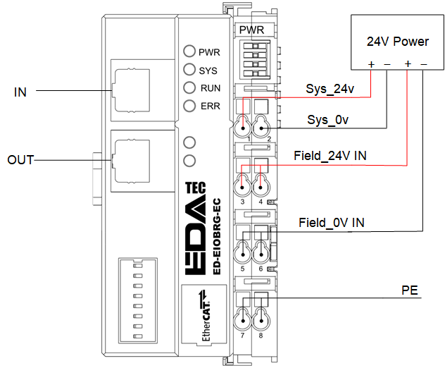
1.1.5.1 Power Supply Interface
The ED-EIOBRG-EC device power interface contains 8 PT terminals with 1 system power port and 2 Field power ports, and the specific port definitions are listed in the following table.
- SYS Power: Access to an external power supply to power the ED-EIOBRG-EC with an input voltage range of DC 24V (±20%) and an input current of 2A (Max).
- Field Power: Access to an external power supply, power supply for extended I/O modules, input voltage range DC 24V (±20%), output current 10A (Max)
| Pin ID | Pin Name | Pin ID | Pin Name |
|---|---|---|---|
| 1 | 24V SYS | 2 | 0V SYS |
| 3 | 24V Field | 4 | 24V Field |
| 5 | 0V Field | 6 | 0V Field |
| 7 | PE | 8 | PE |
1.1.5.2 EtherCAT Interface
The ED-EIOBRG-EC contains 1 EtherCAT IN port and 1 EtherCAT OUT port.
- EtherCAT IN port: It is used for accessing the EtherCAT network, supporting to connect EtherCAT master or EtherCAT OUT port of EtherCAT slaves.
- EtherCAT OUT port: It is used to connect other EtherCAT device on the same network segment, supporting to connect EtherCAT IN port of EtherCAT slaves.
1.1.6 Connection Cables
For the definition of each terminal on ED-EIOBRG-EC device, see 1.1.5 Interface。
1.1.7 Expansion Modules
Supports the expansion of I/O modules on the right side of the ED-EIOBRG-EC, including: digital input modules, digital output modules, relay output modules, analogue input modules, analogue output modules, RTD input modules, thermocouple (TC) input modules, high-speed counter modules and bus end cover.
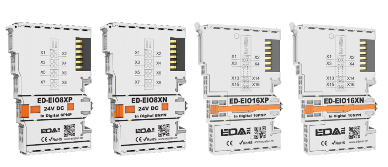
1.2 EtherCAT Digital Input Modules
The EtherCAT digital input modules contain both PNP and NPN signal types, and the specific models included are listed in the table below.
| Model | Description |
|---|---|
| ED-EIO8XP | 8-channel digital input module, PNP type |
| ED-EIO8XN | 8-channel digital input module, NPN type |
| ED-EIO16XP | 16-channel digital input module, PNP type |
| ED-EIO16XN | 16-channel digital input module, NPN type |
1.2.1 Overview
The EtherCAT digital input module include two types of PNP and NPN, supporting 8-channel and 16-channel inputs respectively. It is used for accessing external digital signals and transmitting them to the EtherCAT network, with optocoupler isolation between each channel.
EtherCAT digital input module adopts plug-in appearance structure, which is convenient to install on the right side of EtherCAT coupler or master PLC device. Up to 32 modules can be cascaded without additional power supply. Users can select the appropriate type and number of input channels according to actual requirements.
1.2.2 Packing List
1 x EtherCAT digital input module
1.2.3 Appearance
Introducing the functions and definitions of interfaces on each panel.
ED-EIO8XP: 8-channel digital input module (PNP type)
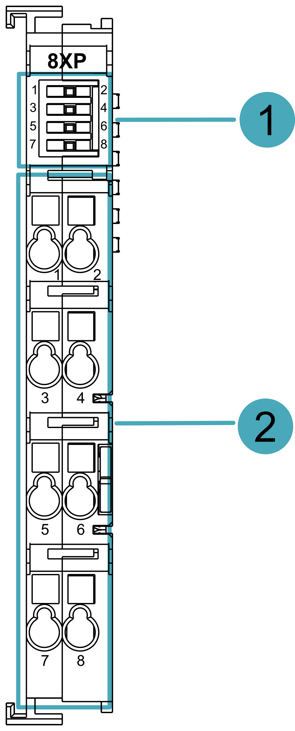
| NO. | Function Definition |
|---|---|
| 1 | 8 x Indicators, green, 1~8 indicate the indicator of 1~8 channels respectively, each channel indicator is independent of each other, including two states of on and off.
|
| 2 | 8 x input ports, channels 1~8 correspond to signals X1~X8 respectively. |
where the input ports are defined in the following table:
| Pin ID | Pin Name | Pin ID | PIN Name |
|---|---|---|---|
| 1 | X1 | 2 | X2 |
| 3 | X3 | 4 | X4 |
| 5 | X5 | 6 | X6 |
| 7 | X7 | 8 | X8 |
ED-EIO16XP: 16-channel digital input module (PNP type)

| NO. | Function Definition |
|---|---|
| 1 | 16 x Indicators, green, 1~16 indicate the indicators of 1~16 channels respectively, each channel indicator is independent of each other, including two states of on and off.
|
| 2 | 16 x input ports, 1~16 channels correspond to signals X1~X16 respectively. |
Where the input ports are defined in the following table:
| Pin ID | Pin Name | Pin ID | Pin Name |
|---|---|---|---|
| 1 | X1 | 2 | X2 |
| 3 | X3 | 4 | X4 |
| 5 | X5 | 6 | X6 |
| 7 | X7 | 8 | X8 |
| 9 | X9 | 10 | X10 |
| 11 | X11 | 12 | X12 |
| 13 | X13 | 14 | X14 |
| 15 | X15 | 16 | X16 |
ED-EIO8XN: 8-channel digital input module (NPN type)
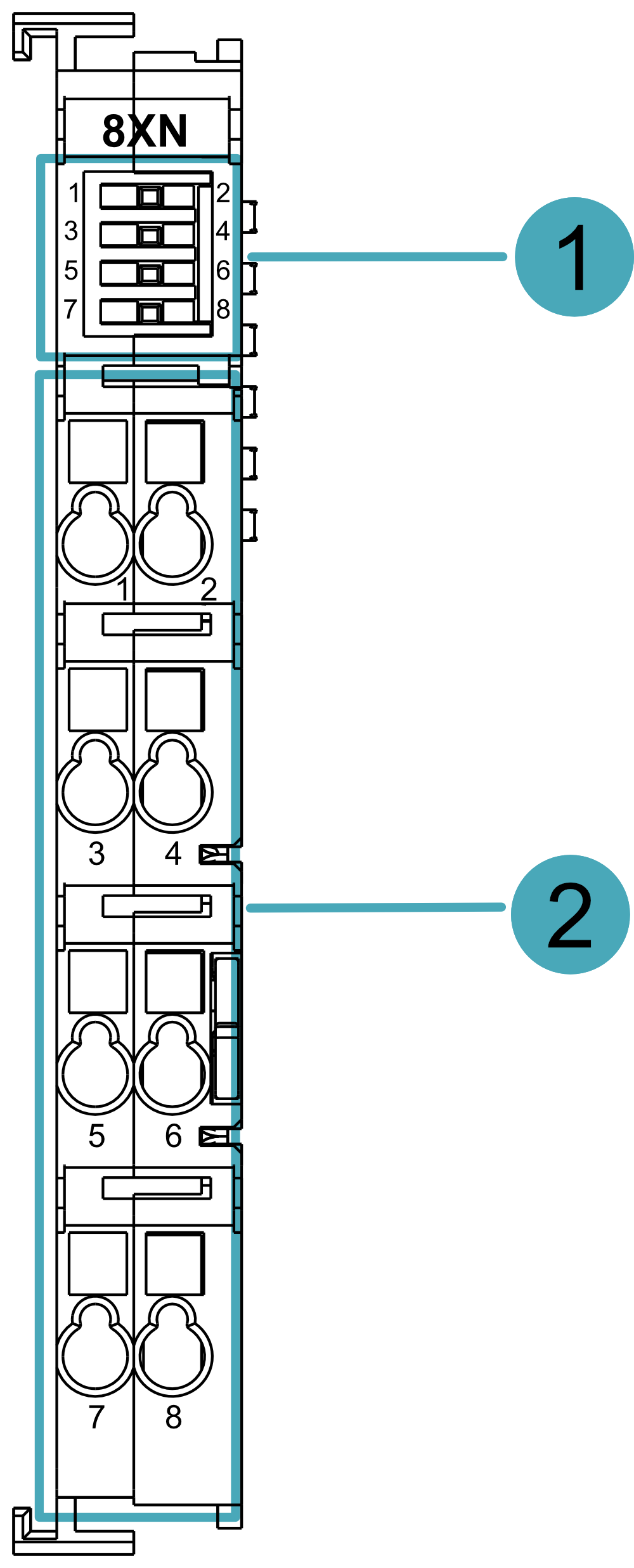
| NO. | Function Definition |
|---|---|
| 1 | 8 x Indicators, green, 1~8 indicate the indicator of 1~8 channels respectively, each channel indicator is independent of each other, including two states of on and off.
|
| 2 | 8 x input ports, channels 1~8 correspond to signals X1~X8 respectively. |
Where the input ports are defined in the following table:
| Pin ID | Pin Name | Pin ID | Pin Name |
|---|---|---|---|
| 1 | X1 | 2 | X2 |
| 3 | X3 | 4 | X4 |
| 5 | X5 | 6 | X6 |
| 7 | X7 | 8 | X8 |
ED-EIO16XN: 16-channel digital input module (NPN type)
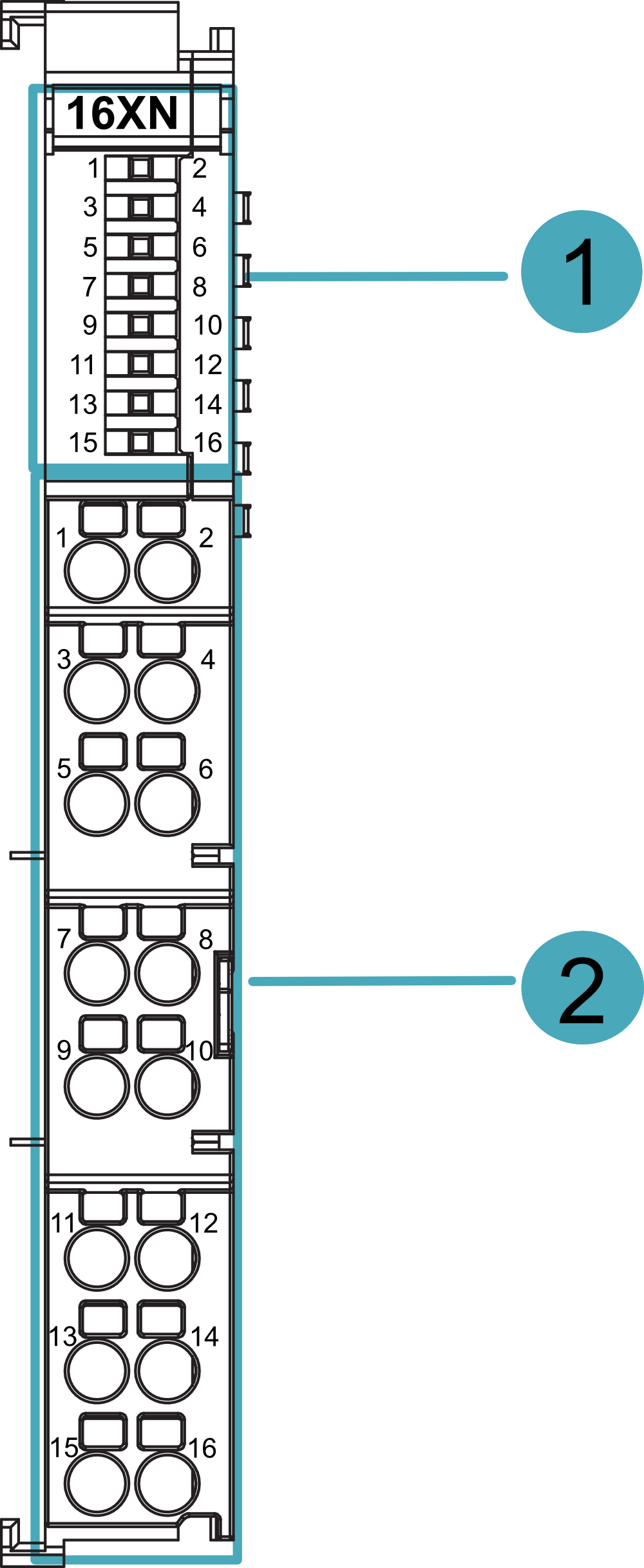
| NO. | Function Definition |
|---|---|
| 1 | 16 x Indicators, green, 1~16 indicates the indicator of 1~16 channels respectively, each channel indicator is independent of each other and contains two states of on and off.
|
| 2 | 16 x input ports, 1~16 channels correspond to signals X1~X16 respectively. |
Where the input ports are defined in the following table:
| Pin ID | Pin Name | Pin ID | Pin Name |
|---|---|---|---|
| 1 | X1 | 2 | X2 |
| 3 | X3 | 4 | X4 |
| 5 | X5 | 6 | X6 |
| 7 | X7 | 8 | X8 |
| 9 | X9 | 10 | X10 |
| 11 | X11 | 12 | X12 |
| 13 | X13 | 14 | X14 |
| 15 | X15 | 16 | X16 |
1.2.4 Connection Cables
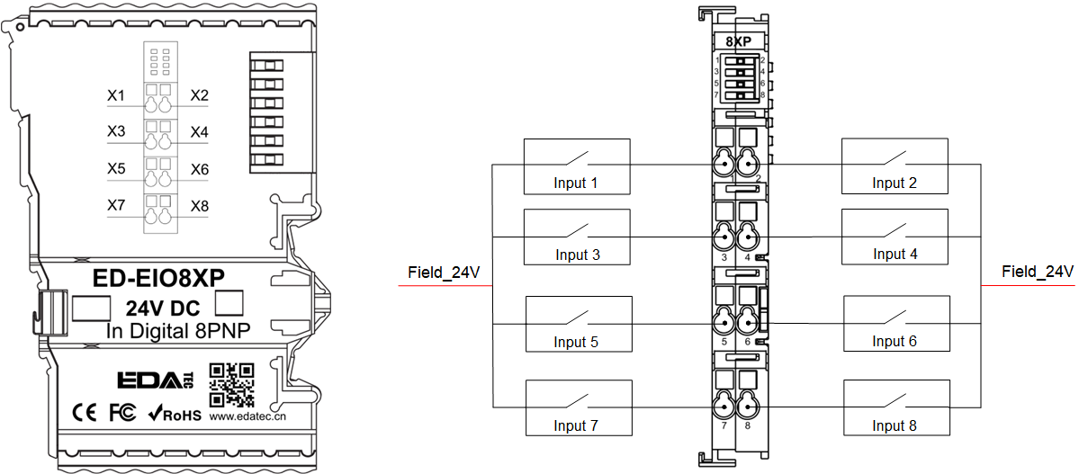
ED-EIO8XP and ED-EIO16XP Digital Input Module (PNP type) Wiring Diagram:
The wiring schematic is shown using the 8-terminal module as an example only:
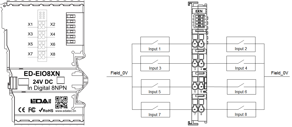
ED-EIO8XN and ED-EIO16XN Digital Input Modules (NPN type) Wiring Diagram:
The wiring schematic is shown using the 8-terminal module as an example only:
1.3 EtherCAT digital output modules
The EtherCAT digital output modules contain both transistor and relay types, where the transistors support both PNP and NPN signal types, and the specific models included are listed in the table below.
| Model | Description |
|---|---|
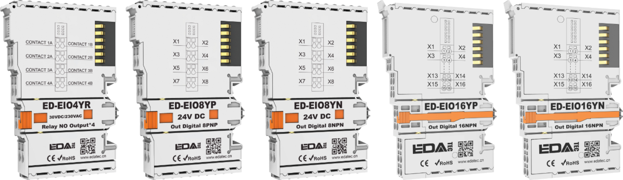
| ED-EIO4YR | 4-channel relay output module |
| ED-EIO8YP | 8-channel digital output module, PNP type |
| ED-EIO8YN | 8-channel digital output module, NPN type |
| ED-EIO16YP | 16-channel digital output module, PNP type |
| ED-EIO16YN | 16-channel digital output module, NPN type |
This section provides a product overview, packing list, appearance, and cable connections for digital output modules.
1.3.1 Overview
The EtherCAT digital output modules include transistors (PNP/NPN) and relay types, supporting 4, 8 and 16 outputs respectively, which are used to transmit control signals from the EtherCAT network to external devices, with optocoupler isolation between each channel. The EtherCAT digital output modules have a plug-in appearance and can be easily mounted on the right side of the EtherCAT coupler or master PLC device. Up to 32 modules can be cascaded without additional power supply, and the user can choose the appropriate type and number of output channels according to actual requirements.
1.3.2 Packing List
1 x EtherCAT digital output module
1.3.3 Appearance
Introducing the functions and definitions of interfaces on each panel.
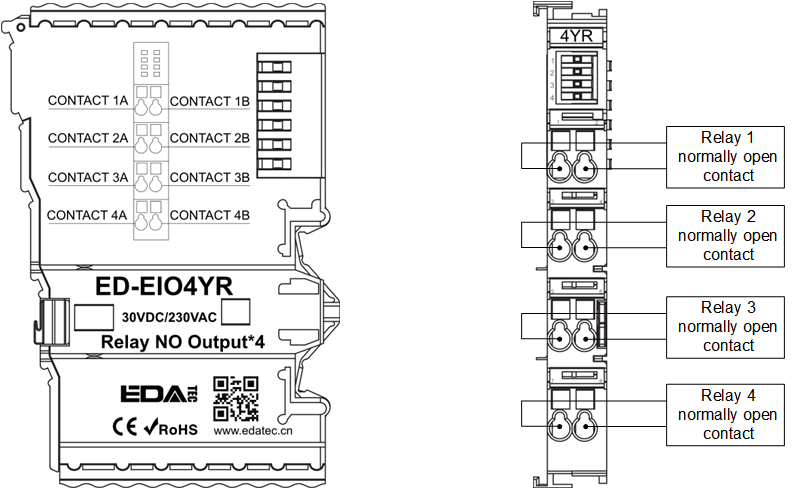
ED-EIO4YR: 4-channel relay output module
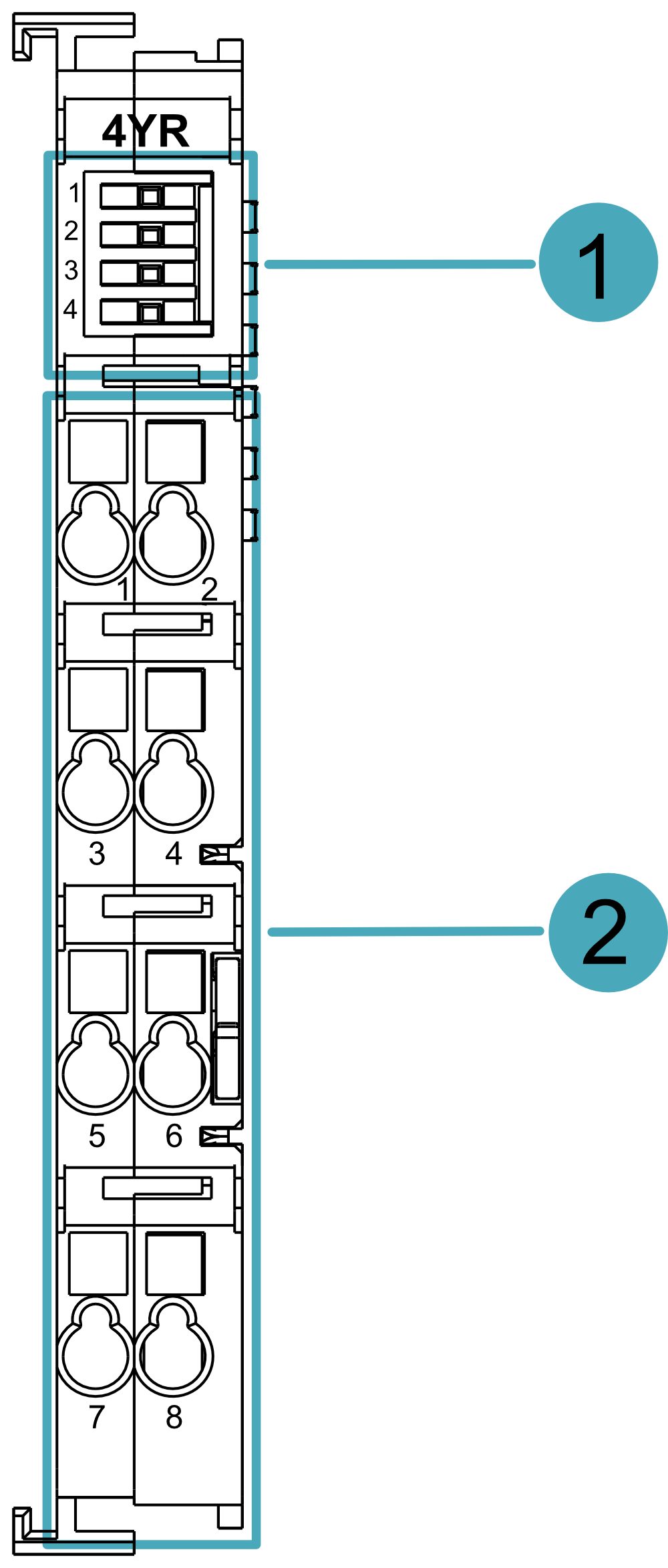
| NO. | Function Definition |
|---|---|
| 1 | 4 x Indicators, green, 1~4 indicate the indicator of 1~4 channels respectively, each channel indicator is independent of each other and contains two states of on and off.
|
| 2 | 8 x output ports, channels 1, 3, 5 and 7 correspond to the signals CONTACT 1A~CONTACT 4A respectively; channels 2, 4, 6 and 8 correspond to the signals CONTACT 1B~CONTACT 4B respectively. |
Where the output ports are defined in the following table:
| Pin ID | Pin Name | Pin ID | Pin Name |
|---|---|---|---|
| 1 | CONTACT 1A | 2 | CONTACT 1B |
| 3 | CONTACT 2A | 4 | CONTACT 2B |
| 5 | CONTACT 3A | 6 | CONTACT 3B |
| 7 | CONTACT 4A | 8 | CONTACT 4B |
ED-EIO8YP: 8-channel digital output module (PNP type)
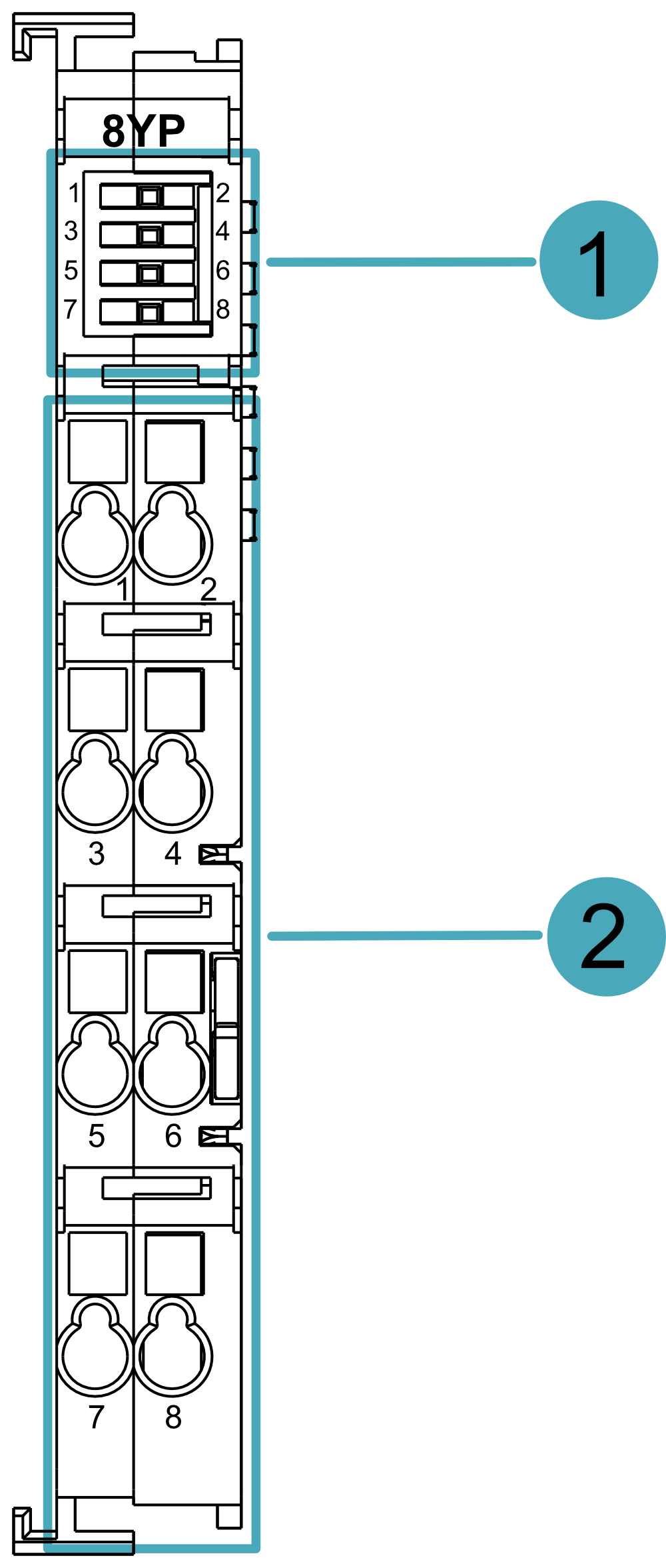
| NO. | Function Definition |
|---|---|
| 1 | 8 x Indicators, 1~8 indicate the indicator of 1~8 channels respectively, each channel indicato is independent of each other, including two states of on and off.
|
| 2 | 8 x output ports, channels 1~8 correspond to signals Y1~Y8 respectively. |
Where the output ports are defined in the following table:
| Pin ID | Pin Name | Pin ID | Pin Name |
|---|---|---|---|
| 1 | Y1 | 2 | Y2 |
| 3 | Y3 | 4 | Y4 |
| 5 | Y5 | 6 | Y6 |
| 7 | Y7 | 8 | Y8 |
ED-EIO16YP: 16-channel digital output module (PNP type)
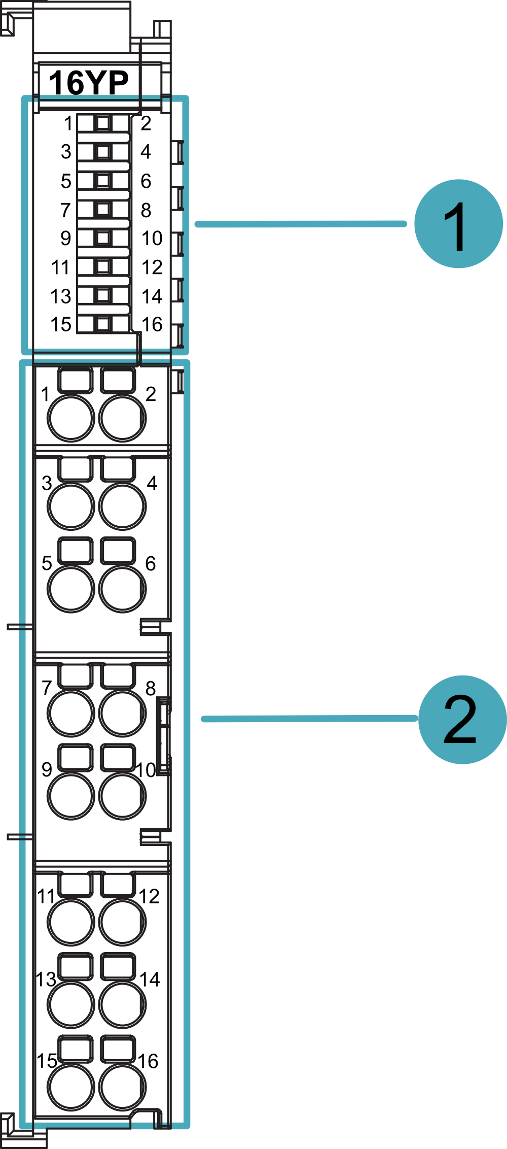
| NO. | Function Definition |
|---|---|
| 1 | 16 x Indicators, 1~16 indicate the indicators of 1~16 channels respectively, each channel indicator is independent of each other, including two states of on and off.
|
| 2 | 16 x output ports, 1~16 channels correspond to signals Y1~Y16 respectively. |
Where the output ports are defined in the following table:
| Pin ID | Pin Name | Pin ID | Pin Name |
|---|---|---|---|
| 1 | Y1 | 2 | Y2 |
| 3 | Y3 | 4 | Y4 |
| 5 | Y5 | 6 | Y6 |
| 7 | Y7 | 8 | Y8 |
| 9 | Y9 | 10 | Y10 |
| 11 | Y11 | 12 | Y12 |
| 13 | Y13 | 14 | Y14 |
| 15 | Y15 | 16 | Y16 |
ED-EIO8YN: 8-channel digital output module (NPN type)
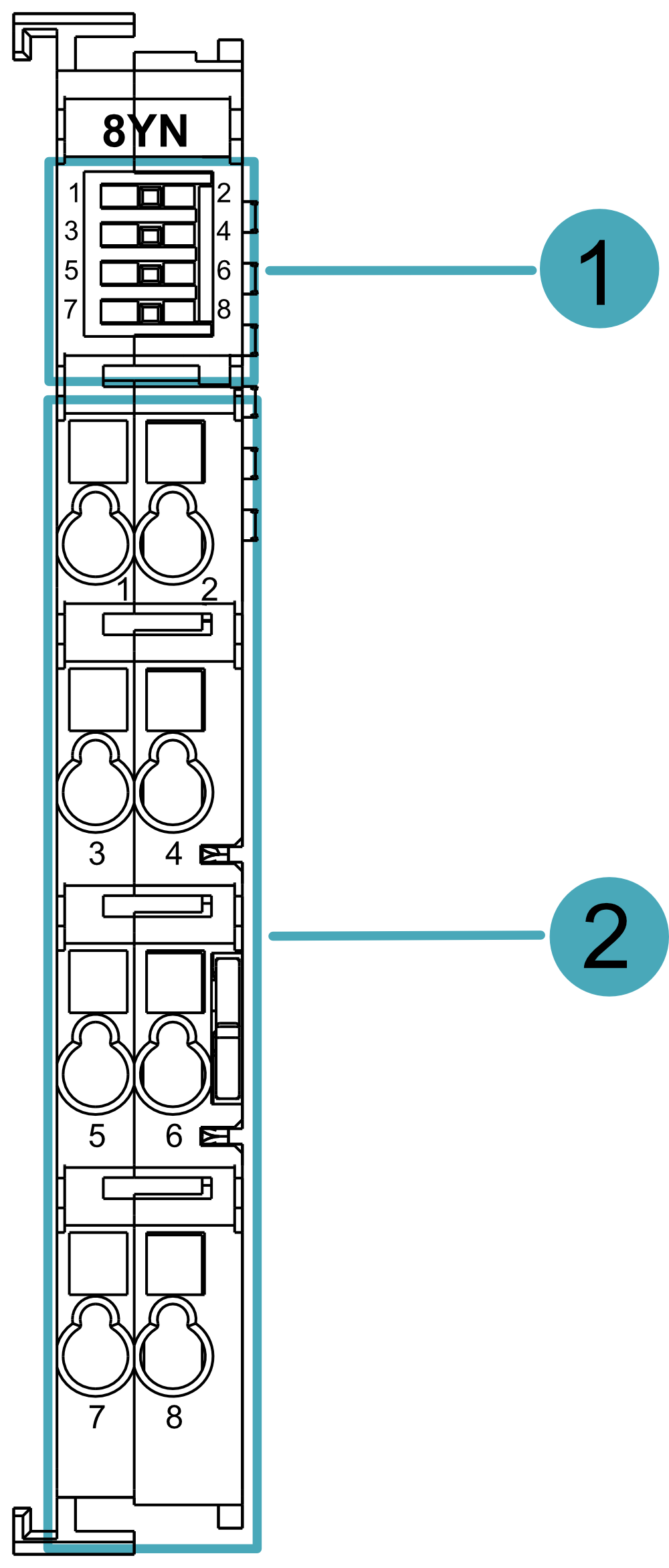
| NO. | Function Definition |
|---|---|
| 1 | 8 x Indicators, 1~8 indicate the indicator of 1~8 channels respectively, each channel indicator is independent of each other, including two states of on and off.
|
| 2 | 8 x output ports, channels 1~8 correspond to signals Y1~Y8 respectively. |
Where the output ports are defined in the following table:
| Pin ID | Pin Name | Pin ID | Pin Name |
|---|---|---|---|
| 1 | Y1 | 2 | Y2 |
| 3 | Y3 | 4 | Y4 |
| 5 | Y5 | 6 | Y6 |
| 7 | Y7 | 8 | Y8 |
ED-EIO16YP: 16-channel digital output module (NPN type)

| NO. | Function Definition |
|---|---|
| 1 | 16 x Indicator, green, 1~16 indicates the indicator of 1~16 channels respectively, each channel indicator is independent of each other and contains two states of on and off.
|
| 2 | 16 x output ports, 1~16 channels correspond to signals Y1~Y16 respectively. |
Where the output ports are defined in the following table:
| Pin ID | Pin Name | Pin ID | Pin Name |
|---|---|---|---|
| 1 | Y1 | 2 | Y2 |
| 3 | Y3 | 4 | Y4 |
| 5 | Y5 | 6 | Y6 |
| 7 | Y7 | 8 | Y8 |
| 9 | Y9 | 10 | Y10 |
| 11 | Y11 | 12 | Y12 |
| 13 | Y13 | 14 | Y14 |
| 15 | Y15 | 16 | Y16 |
1.3.4 Connection Cables
ED-EIO4YR Relay Output Module Wiring Diagram:
ED-EIO8YP and ED-EIO16YP digital output modules (PNP type) wiring diagram:
The wiring schematic is shown using the 8-terminal module as an example only:
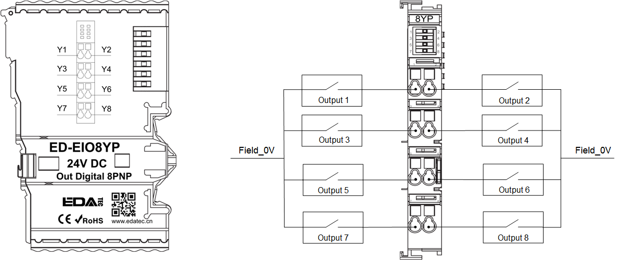
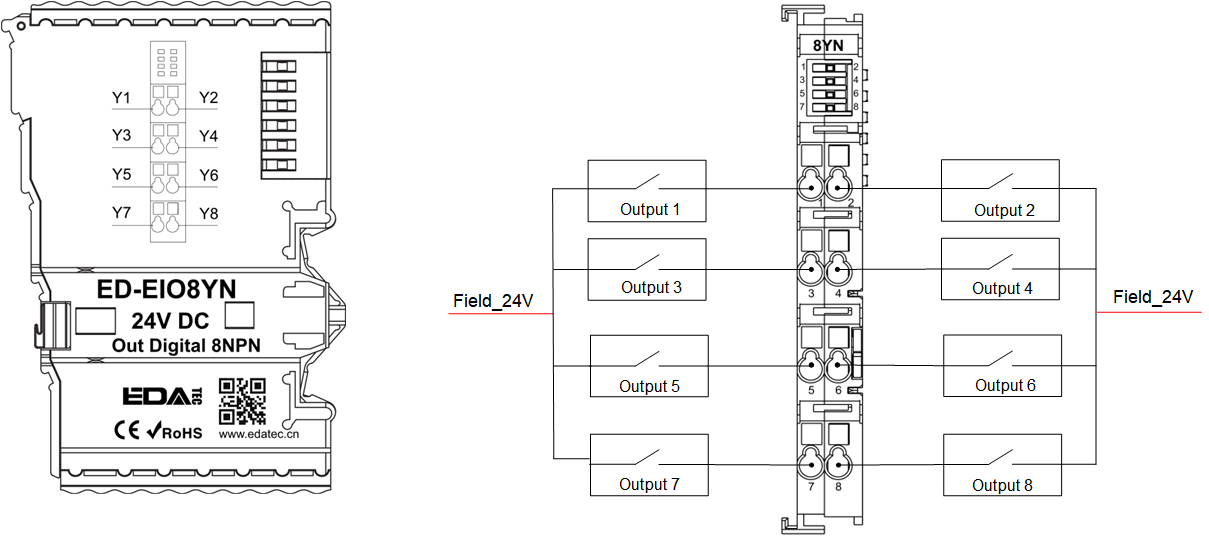
ED-EIO8YN and ED-EIO16YN digital output modules (NPN type) wiring diagram:
The wiring schematic is shown using the 8-terminal module as an example only:
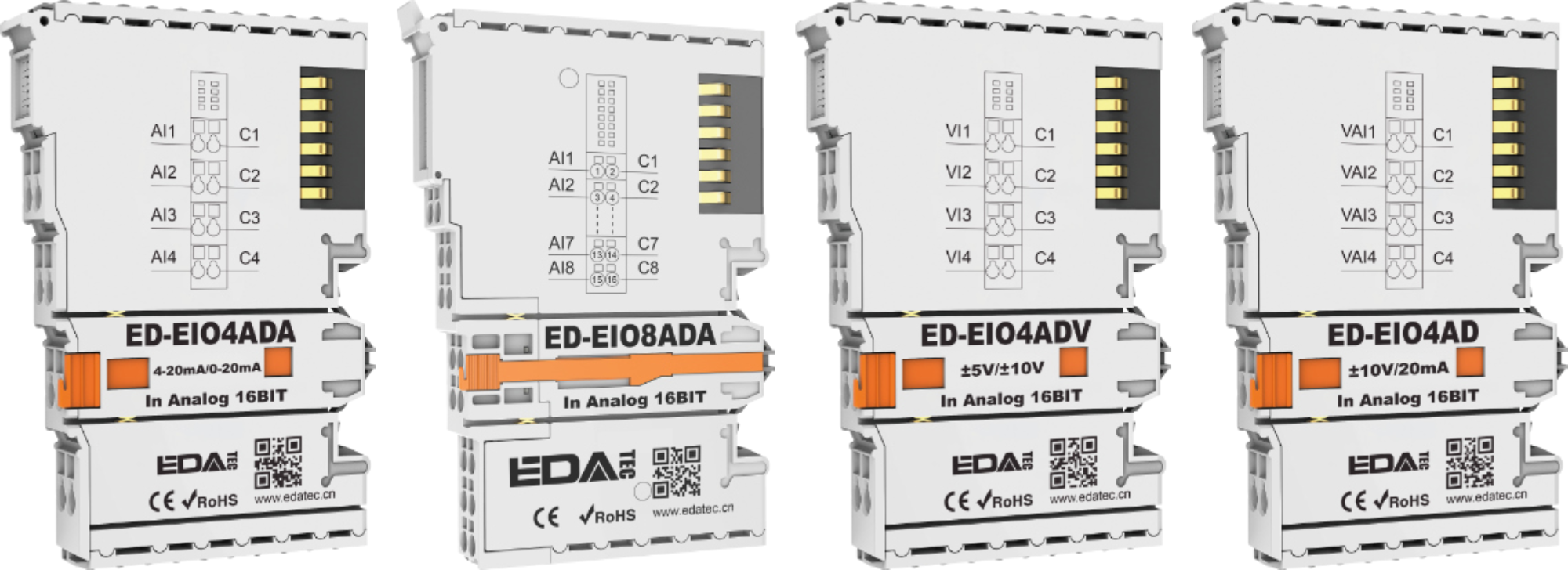
1.4 EtherCAT analog input modules
The EtherCAT analog input modules are available as current inputs, voltage inputs and current/voltage hybrids, with the specific models listed in the table below.
| Model | Description |
|---|---|
| ED-EIO4ADA | 4-channel current input module, 4-20mA/0-20mA, configurable |
| ED-EIO8ADA | 8-channel current input module, 4-20mA/0-20mA, configurable |
| ED-EIO4ADV | 4-channel voltage input module, -5~5V/0~10V/-10~10V, configurable |
| ED-EIO4AD | 4-channel mixed voltage/current input module, -5~5V/0~10V/-10~10V/4-20mA/0-20mA, configurable |
This section provides a product overview, packing list, appearance, and cable connections for analog input modules.
1.4.1 Overview
The EtherCAT analog input modules with 3 types of current input, voltage input and current/voltage mixing that support 4 and 8 signal inputs, respectively, to receive external analog signals and transmit them to the EtherCAT network.
The EtherCAT analogue input modules have a plug-in appearance and are easy to install on the right side of the EtherCAT coupler or master PLC device. Up to 32 modules can be cascaded without additional power supply. Users can select the appropriate type and number of input channels according to actual requirements.
1.4.2 Packing List
1 x EtherCAT analog input module
1.4.3 Appearance
Introducing the functions and definitions of interfaces on each panel.
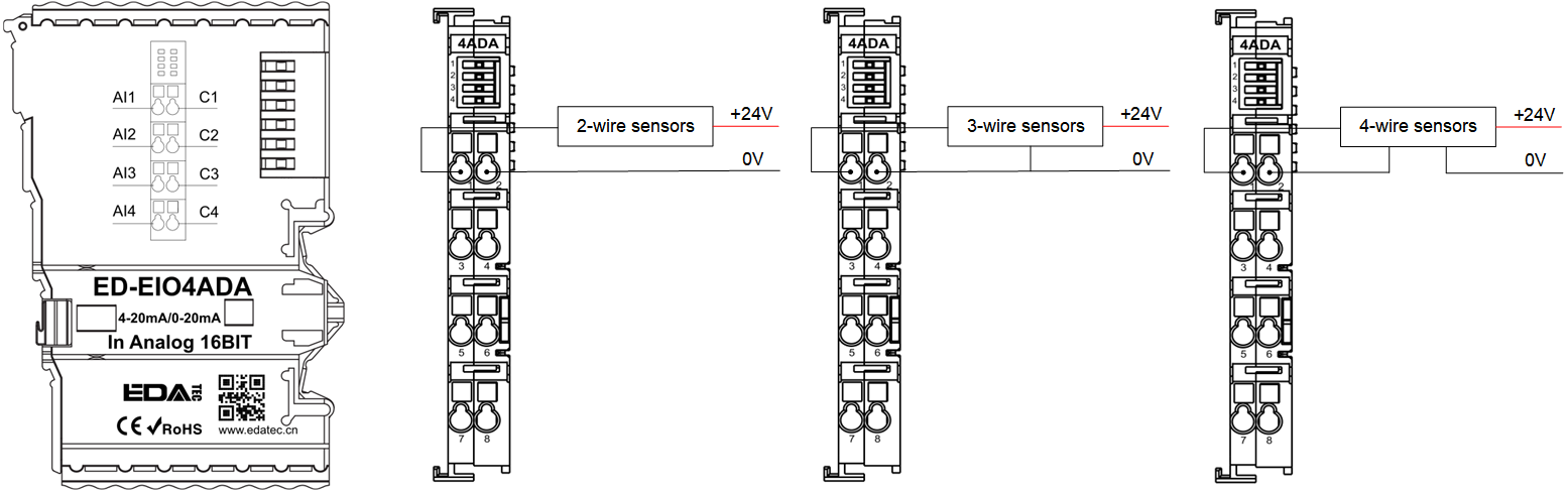
ED-EIO4ADA: 4-Channel Current Input Module

| NO. | Function Definition |
|---|---|
| 1 | 4 x Indicators, 1~4 indicate the indicator of AI1/C1~AI4/C4 channels respectively, each channel indicator is independent of each other and contains three states of on, blink and off.
|
| 2 | 8 x input ports, channels 1, 3, 5 and 7 correspond to signals AI1~AI4 respectively. channels 2, 4, 6 and 8 correspond to signals C1~C4 respectively. |
Where the input ports are defined in the following table:
| Pin ID | Pin Name | Pin ID | Pin Name |
|---|---|---|---|
| 1 | AI1 | 2 | C1 |
| 3 | AI2 | 4 | C2 |
| 5 | AI3 | 6 | C3 |
| 7 | AI4 | 8 | C4 |
ED-EIO8ADA: 8-Channel Current Input Module
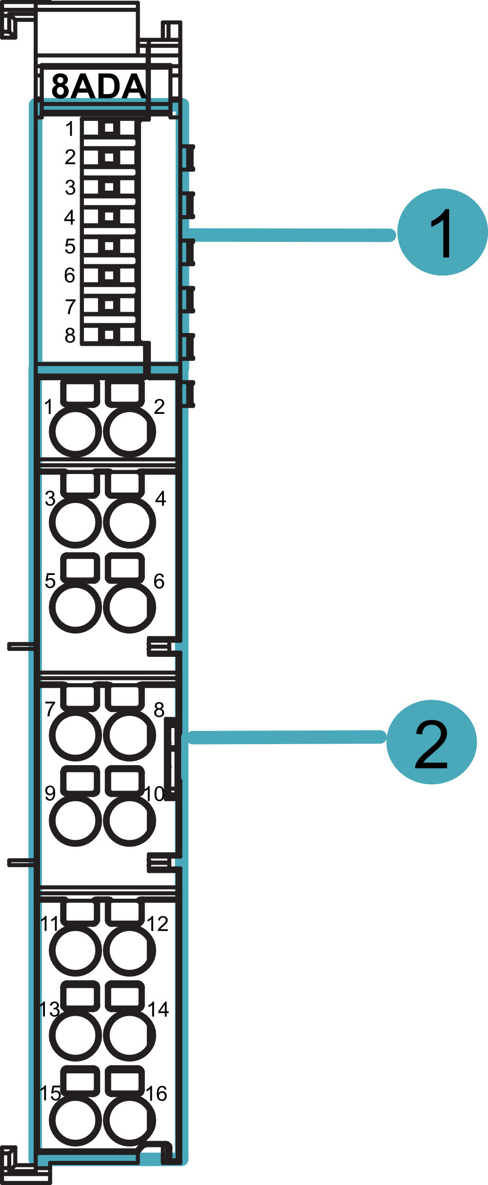
| NO. | Function Definition |
|---|---|
| 1 | 8 x Indicators, 1~8 indicate the indicator of AI1/C1~AI8/C8 channels respectively, and the indicator lamps of each channel are independent of each other, including three states of on, blink and off.
|
| 2 | 16 x input ports, channels 1, 3, 5, 7, 9, 11, 13 and 15 correspond to signals AI1~AI8 respectively. channels 2, 4, 6, 8, 10, 12, 14 and 16 correspond to signals C1~C8 respectively. |
Where the input ports are defined in the following table:
| Pin ID | Pin Name | Pin ID | Pin Name |
|---|---|---|---|
| 1 | AI1 | 2 | C1 |
| 3 | AI2 | 4 | C2 |
| 5 | AI3 | 6 | C3 |
| 7 | AI4 | 8 | C4 |
| 9 | AI5 | 10 | C5 |
| 11 | AI6 | 12 | C6 |
| 13 | AI7 | 14 | C7 |
| 15 | AI8 | 16 | C8 |
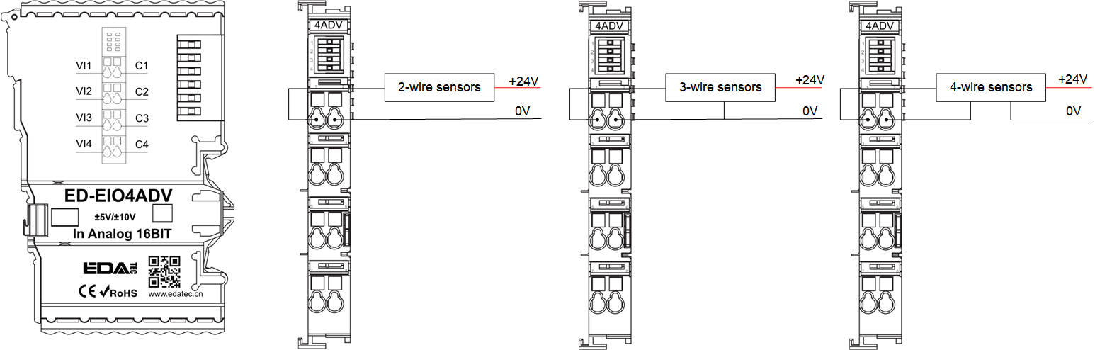
ED-EIO4ADV: 4-Channel Voltage Input Module

| NO. | Function Definition |
|---|---|
| 1 | 4 x Indicators, 1~4 indicate the indicator of VI1/C1~VI4/C4 channels respectively, each channel indicator is independent of each other and contains three states of on, blink and off.
|
| 2 | 8 x input ports, channels 1, 3, 5 and 7 correspond to signals VI1~VI4 respectively. channels 2, 4, 6 and 8 correspond to signals C1~C4 respectively. |
Where the input ports are defined in the following table:
| Pin ID | Pin Name | Pin ID | Pin Name |
|---|---|---|---|
| 1 | VI1 | 2 | C1 |
| 3 | VI2 | 4 | C2 |
| 5 | VI3 | 6 | C3 |
| 7 | VI4 | 8 | C4 |
ED-EIO4AD: 4-Channel Voltage/Current Mixed Input Module

| NO. | Function Definition |
|---|---|
| 1 | 4 x Indicators, green, 1~4 indicate the indicator of VAI1/C1~VAI4/C4 channels respectively, each channel indicator is independent of each other and contains three states of on, blink and off.
|
| 2 | 8 x input ports, channels 1, 3, 5 and 7 correspond to signals VAI1~VAI4 respectively. channels 2, 4, 6 and 8 correspond to signals C1~C4 respectively. |
Where the input ports are defined in the following table:
| Pin ID | Pin Name | Pin ID | Pin Name |
|---|---|---|---|
| 1 | VAI1 | 2 | C1 |
| 3 | VAI2 | 4 | C2 |
| 5 | VAI3 | 6 | C3 |
| 7 | VAI4 | 8 | C4 |
1.4.4 Connection Cables
Analogue current input modules ED-EIO4ADA and ED-EIO8ADA wiring diagram:
The wiring is illustrated using the 4-channel current input module as an example only:
Analogue voltage input module ED-EIO4ADV wiring diagram:
Analogue voltage/current hybrid input module ED-EIO4AD wiring diagram:
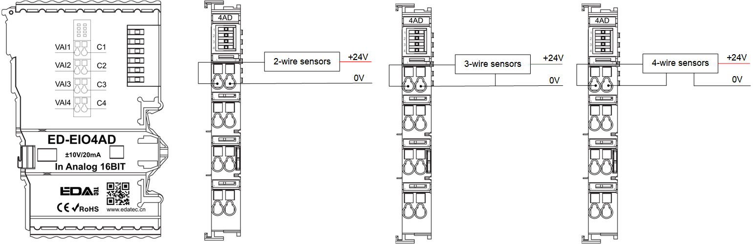
TIP
ED-EIO4AD module for the voltage input, wiring needs to distinguish between the odd channel access voltage positive, the even number of channels access voltage negative, for the current input access without distinguishing between positive and negative.
1.5 EtherCAT analog output modules
The EtherCAT analog output modules include two types of current output and voltage output, which are listed in the table below.
| Model | Description |
|---|---|
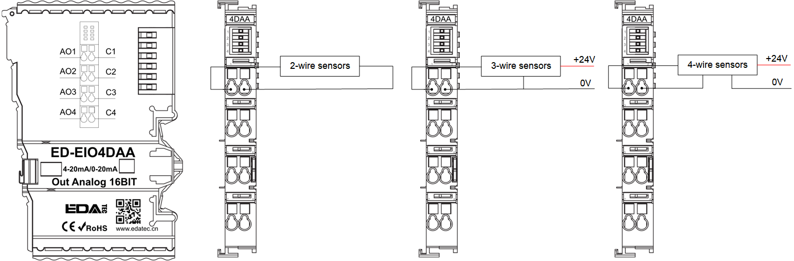
| ED-EIO4DAA | 4-channel current output module, 4-20mA/0-20mA, configurable |
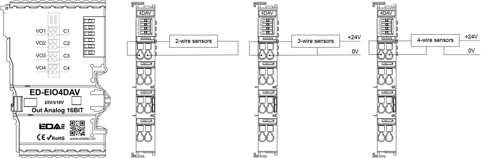
| ED-EIO4DAV | 4-channel voltage output module, -5~5V/0~10V/-10~10V, configurable |
This section provides a product overview, packing list, appearance, and cable connections for analog input modules.
1.5.1Overview
The EtherCAT analog output modules include two types of current output and voltage output, and support 4-channel outputs for converting digital control signals into continuously changing analog signals. The EtherCAT analogue output modules have a plug-in construction and can be easily mounted on the right side of the EtherCAT coupler or master PLC device. Up to 32 modules can be cascaded without additional power supply. Users can select the appropriate type and number of output channels according to actual requirements.
1.5.2 Packing List
1 x EtherCAT analog output module
1.5.3 Appearance
Introducing the functions and definitions of interfaces on each panel.
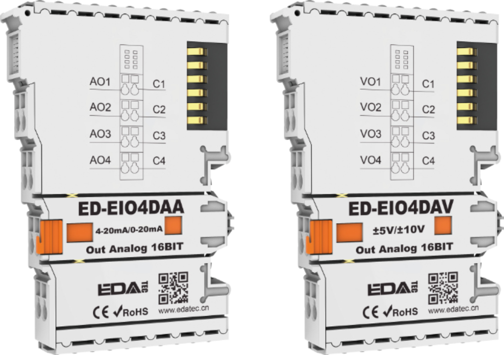
ED-EIO4ADAA: 4-channel current output module
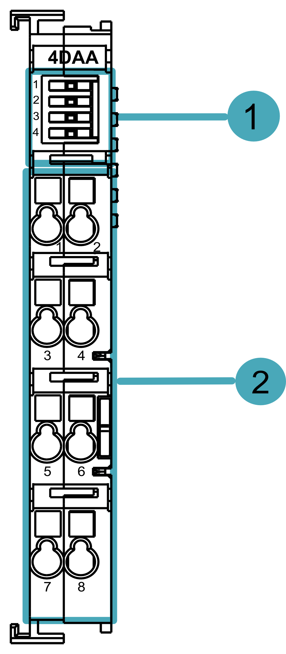
| NO. | Function Definition |
|---|---|
| 1 | 4 x Indicators, 1~4 indicate the indicator of AO1/C1~AO4/C4 channels respectively, each channel indicator is independent of each other and including two states of blink and off.
|
| 2 | 8 x output ports, channels 1, 3, 5 and 7 correspond to signals AO1~AO4 respectively. channels 2, 4, 6 and 8 correspond to signals C1~C4 respectively. |
Where the output ports are defined in the following table:
| Pin ID | Pin Name | Pin ID | Pin Name |
|---|---|---|---|
| 1 | AO1 | 2 | C1 |
| 3 | AO2 | 4 | C2 |
| 5 | AO3 | 6 | C3 |
| 7 | AO4 | 8 | C4 |
ED-EIO4ADAA: 4-channel voltage output module

| NO. | Function Definition |
|---|---|
| 1 | 4 x Indicators, green, 1~4 indicate the indicators of VO1/C1~VO4/C4 channels respectively, each channel indicator is independent of each other and including two states of blink and off.
|
| 2 | 8 x output ports, channels 1, 3, 5 and 7 correspond to signals VO1~AVO4 respectively. channels 2, 4, 6 and 8 correspond to signals C1~C4 respectively. |
Where the output ports are defined in the following table:
| Pin ID | Pin Name | Pin ID | Pin Name |
|---|---|---|---|
| 1 | VO1 | 2 | C1 |
| 3 | VO2 | 4 | C2 |
| 5 | VO3 | 6 | C3 |
| 7 | VO4 | 8 | C4 |
1.5.4 Connection Cables
Analogue current output module ED-EIO4DAA wiring diagram:
Analogue voltage output module ED-EIO4DAV wiring diagram:
1.6 EtherCAT Temperature Input Modules
The EtherCAT Temperature Input Modules are available in two types, RTD and thermocouple, as shown in the table below.
| Model | Description |
|---|---|
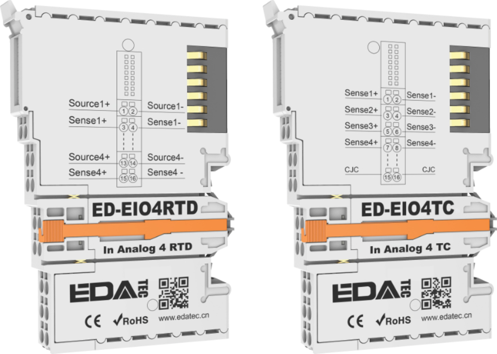
| ED-EIO4RTD | 4-Channel RTD Module |
| ED-EIO4TC | 4-Channel Thermocouple Module |
This section provides a product overview, packing list, appearance, and cable connections for temperature input modules.
1.6.1 Overview
The EtherCAT Temperature Input Module include two types of RTDs and thermocouples and supports 4-channel signal inputs with RTDs of types PT100, PT200, PT500, PT1000 and Ni20 and thermocouples of types K, J, T, E, N, S, R, B, and C. It is used to measure temperatures and transmit temperature data to the EtherCAT network. The EtherCAT temperature input modules have a plug-in appearance and are easy to install on the right side of an EtherCAT coupler or master PLC device. Up to 32 modules are supported in cascade without additional power supply, and the user can select the appropriate type according to actual requirements.
1.6.2 Packing List
1 x EtherCAT temperature input module
1.6.3 Appearance
Introducing the functions and definitions of interfaces on each panel.
ED-EIO4RTD: 4-channel RTD module
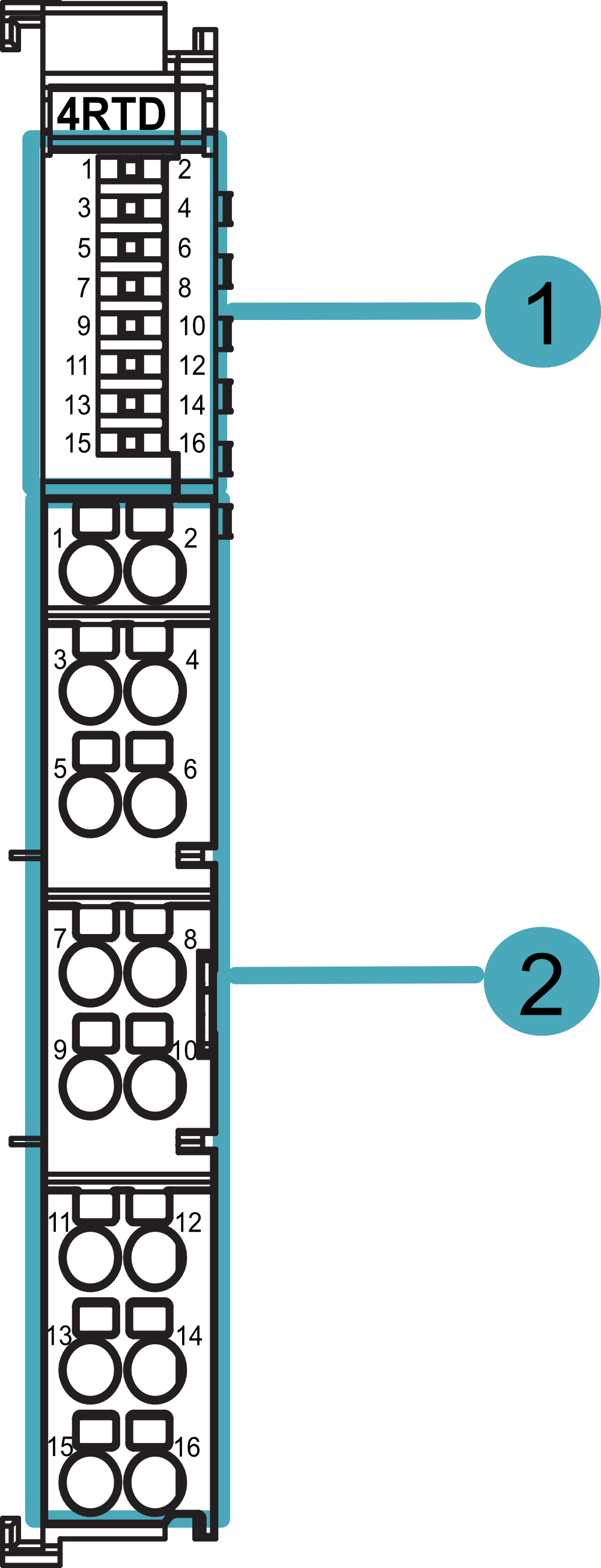
| NO. | Function Definition |
|---|---|
| 1 | 4 x Indicators, 1, 3, 5 and 7 indicate the indicator for channels 1~4 respectively, the indicator include two states of blink and off.
|
| 2 | 16 x Input ports, the detailed port Pin Name is shown in the table below. |
Where the input ports of ED-EIO4RTD are defined in the following table:
| Pin ID | Pin Name | Pin ID | Pin Name |
|---|---|---|---|
| 1 | Source1+ | 2 | Source1- |
| 3 | Sense1+ | 4 | Sense1- |
| 5 | Source2+ | 6 | Source2- |
| 7 | Sense2+ | 8 | Sense2- |
| 9 | Source3+ | 10 | Source3- |
| 11 | Sense3+ | 12 | Sense3- |
| 13 | Source4+ | 14 | Source4- |
| 15 | Sense4+ | 16 | Sense4- |
ED-EIO4TC: 4-channel thermocouple module
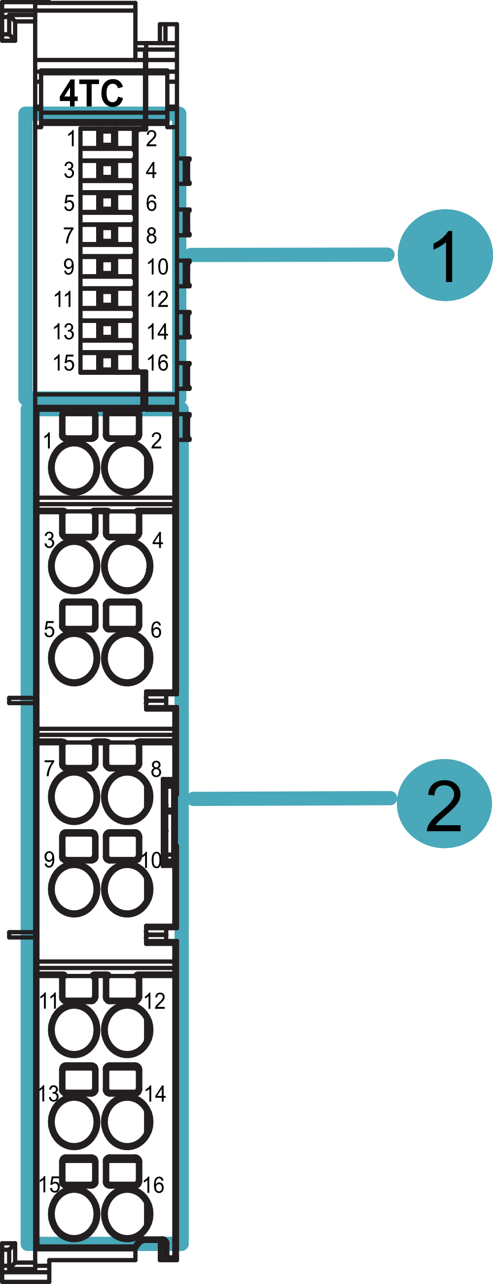
| NO. | Function Definition |
|---|---|
| 1 | 4 x Indicators, Green, 1, 3, 5, 7 indicate the indicator for channels 1~4 respectively, the indicator contain two states of blink and off.
|
| 2 | 16 x Input ports, the detailed port Pin Name is shown in the table below. |
Where the input ports of ED-EIO4TC are defined in the following table:
| Pin ID | Pin Name | Pin ID | Pin Name |
|---|---|---|---|
| 1 | Sense1+ | 2 | Sense1- |
| 3 | Sense2+ | 4 | Sense2- |
| 5 | Sense3+ | 6 | Sense3- |
| 7 | Sense4+ | 8 | Sense4- |
| 9 | NC | 10 | NC |
| 11 | NC | 12 | NC |
| 13 | NC | 14 | NC |
| 15 | CJC | 16 | CJC |
1.6.4 Connection Cables
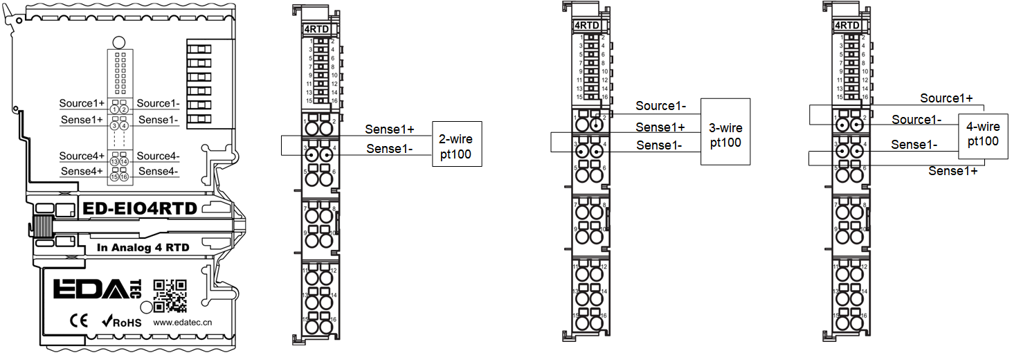
ED-EIO4RTD: 4-channel RTD module wiring diagram:
Take pt100 RTD wiring as an example:
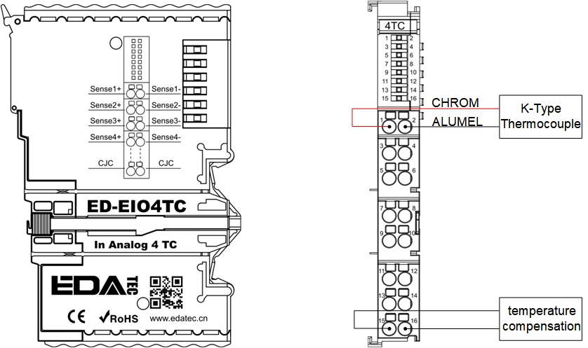
ED-EIO4TC: 4-Channel Thermocouple Module Wiring Diagram:
Take type K thermocouple wiring as an example:
1.7 EtherCAT High Speed Counter Module
The EtherCAT High-Speed Counter Module is a 2-channel differential high-speed counter module with the following model numbers.
| Model | Description |
|---|---|
| ED-EIO2HCD | 2-channel high-speed counter module |
This section provides a product overview, packing list, appearance, and cable connections for high-speed counter module.
1.7.1 Overview
The ED-EIO2HCD is a 2-channel differential high-speed counter module for counting devices (e.g. handwheels or quadrature encoders, etc.) in the industrial field.
The EtherCAT high-speed counter module has a plug-in structure, which makes it easy to be mounted on the right-hand side of an EtherCAT coupler or master PLC device. Up to 32 modules are supported in cascade without additional power supply.
1.7.2 Packing List
1 x EtherCAT high-speed counter module
1.7.3 Appearance
Introducing the functions and definitions of interfaces on each panel.
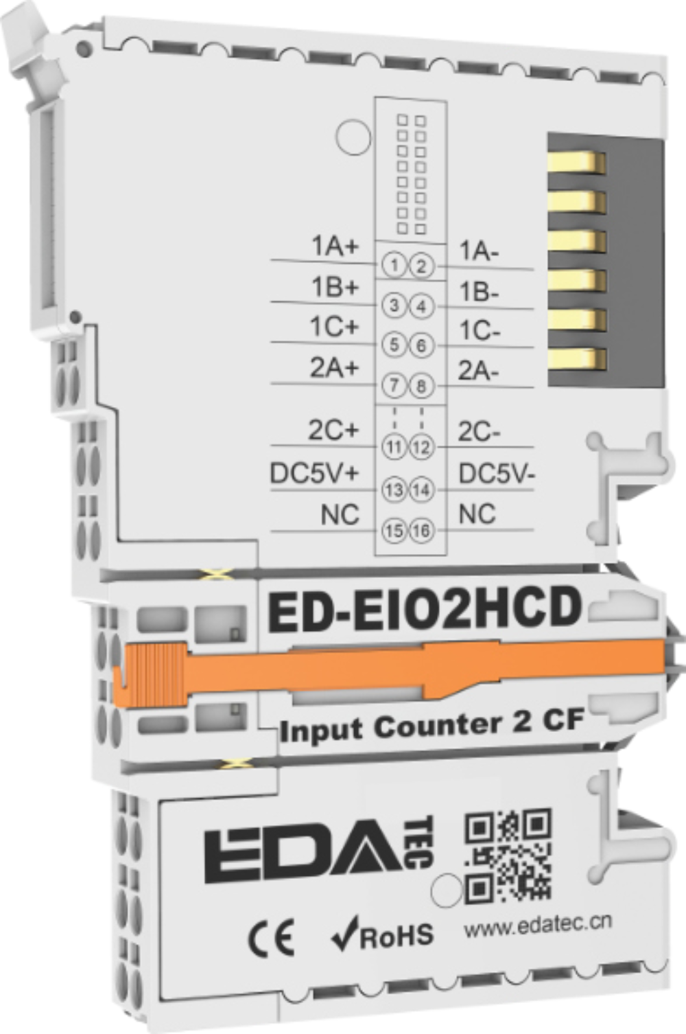
ED-EIO2HCD: 2-channel differential high-speed counter module

| NO. | Function Definition |
|---|---|
| 1 | 6 x Indicators, green, 1, 3 and 5 correspond to channel 1, 2, 4 and 6 correspond to channel 2, the indicator contain three states of on, blink and off.
|
| 2 | 16 x Input Ports,, the detailed port Pin Name is shown in the table below. |
where the input ports of ED-EIO2HCD are defined in the following table:
| Pin ID | Pin Name | Pin ID | Pin Name |
|---|---|---|---|
| 1 | 1A+ | 2 | 1A- |
| 3 | 1B+ | 4 | 1B- |
| 5 | 1C+ | 6 | 1C- |
| 7 | 2A+ | 8 | 2A- |
| 9 | 2B+ | 10 | 2B- |
| 11 | 2C+ | 12 | 2C- |
| 13 | DC5V+ | 14 | DC5V- |
| 15 | NC | 16 | NC |
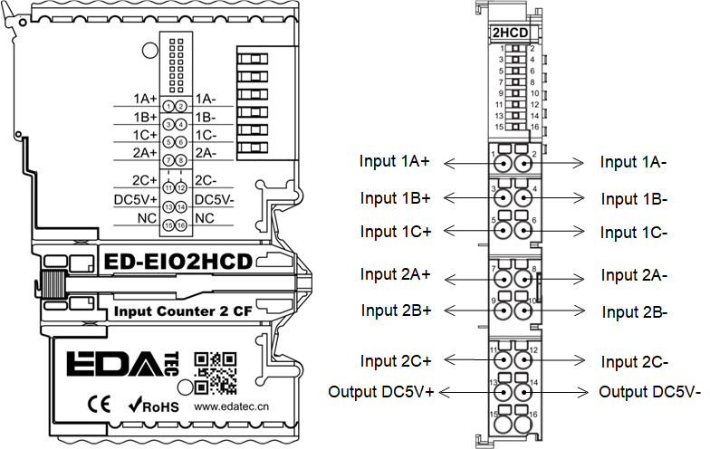
1.7.4 Connection Cables
ED-EIO2HCD: 2-channel differential high-speed counter module wiring diagram:
1.8 EtherCAT Power Expansion Modules
The specific models of the EtherCAT power extension modules are listed in the table below.
| Model | Description |
|---|---|
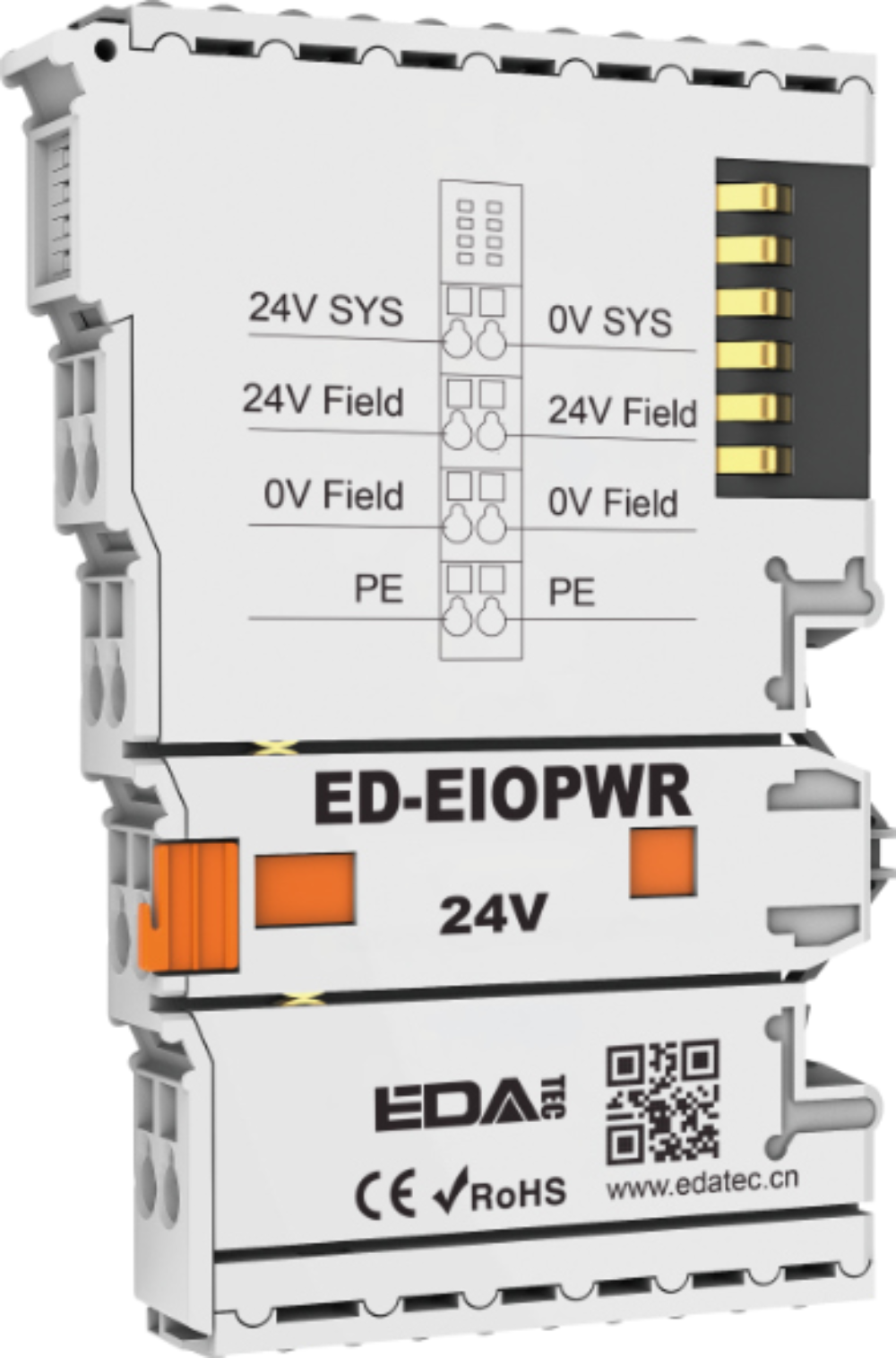
| ED-EIOPWR | Power Expansion Module |
This section provides a product overview, packing list, appearance, and cable connections for power extension module.
1.8.1 Overview
The power supply expansion module is mainly used to provide stable and reliable power supply for the devices in EtherCAT network, which can increase the power capacity of the system and meet the power supply requirements of more devices. The plug-in structure supports DIN-rail mounting, with over-current protection, over-voltage protection, short-circuit protection and other functions to ensure the safe operation of the system.
1.8.2 Packing List
1 x Power Expansion Module
1.8.3 Appearance
Introducing the functions and definitions of interfaces on each panel.
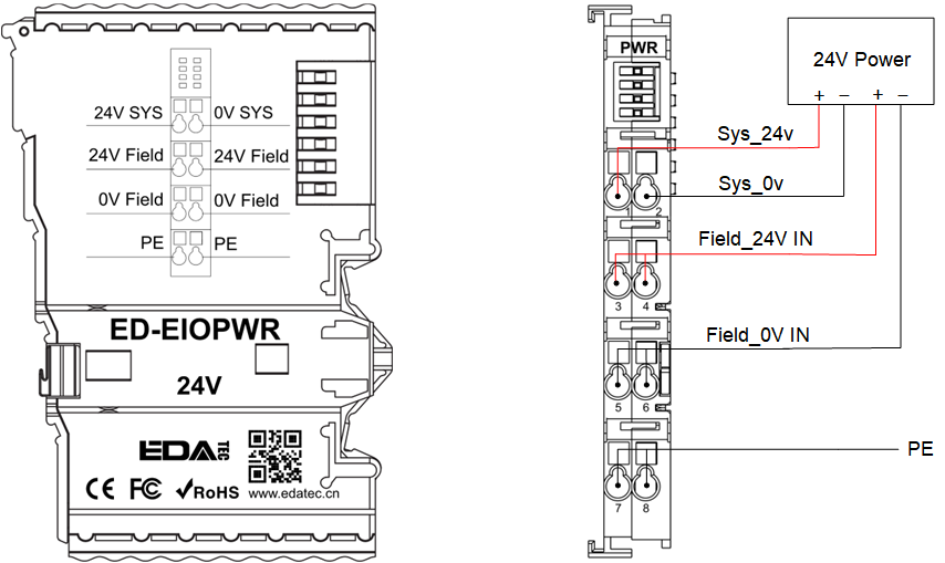
ED-EIOPWR: Power Expansion Module
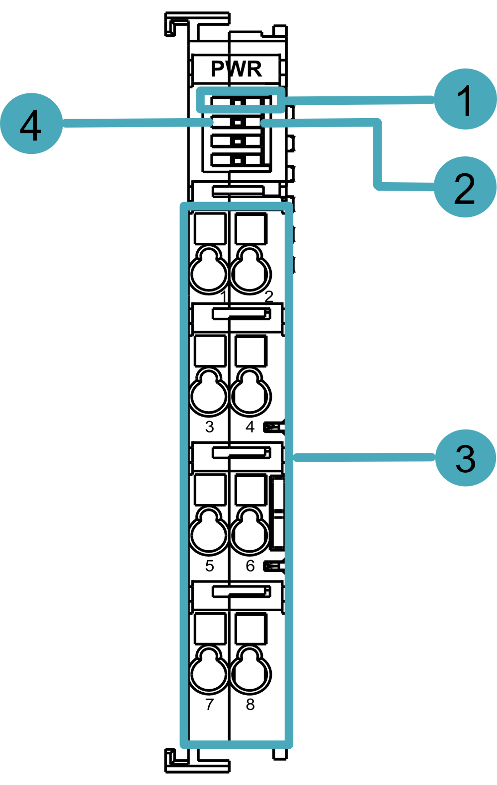
| NO. | Function Definition |
|---|---|
| 1 | 2 x Connection indicators, green, to see if the connection at the common end is working.
|
| 2 | 1 x Input voltage indicator, green, to see if the input voltage is normal.
|
| 3 | 8 x power ports, the detailed port Pin Names are listed in the table below. |
| 4 | 1 x Overcurrent indicator, red, to see if the coupler exceeds the maximum operating current.
|
where the ports of ED-EIOPWR are defined in the following table:
| Pin ID | Pin Name | Pin ID | Pin Name |
|---|---|---|---|
| 1 | 24V SYS | 2 | 0V SYS |
| 3 | 24V Field | 4 | 24V Field |
| 5 | 0V Field | 6 | 0V Field |
| 7 | PE | 8 | PE |
1.8.4 Connection Cables
ED-EIOPWR: Power Expansion Module Wiring Diagram:
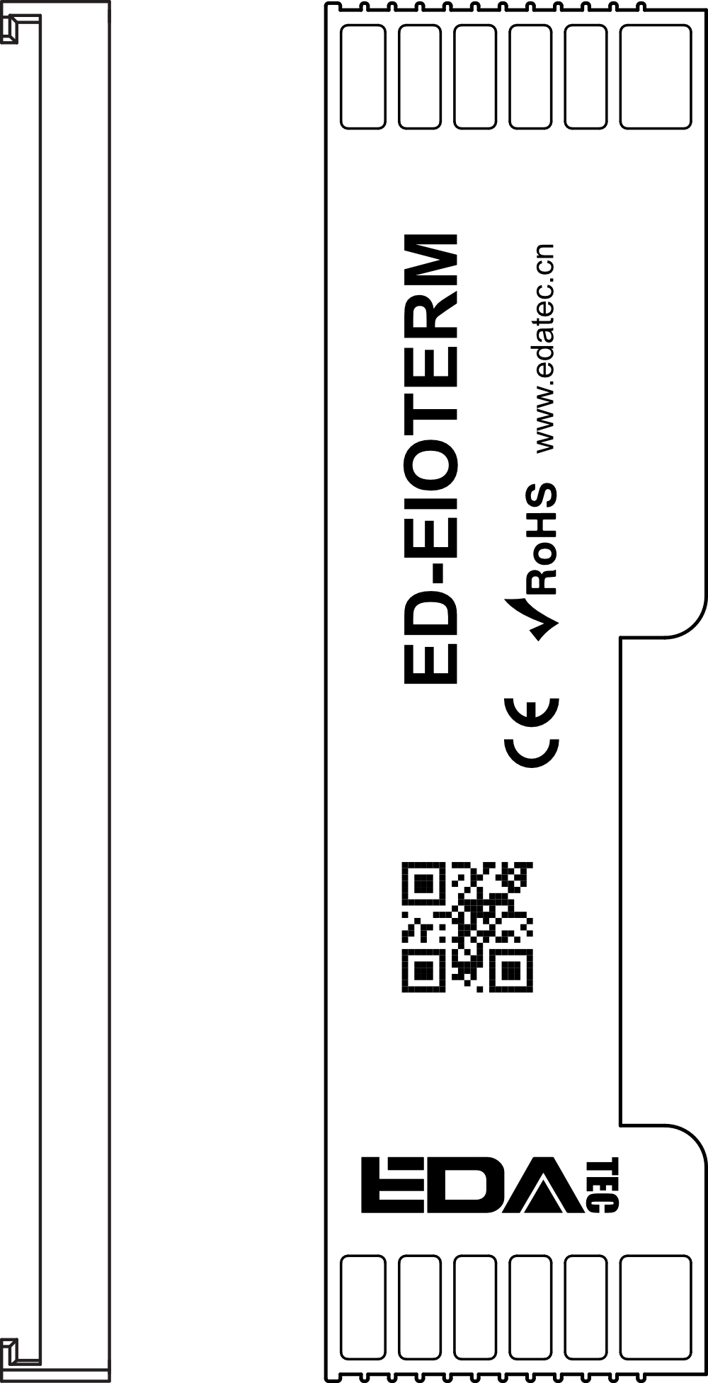
1.9 Bus End Cover
The specific model of Bus End cover is listed in the table below.
| Model | Description |
|---|---|
| ED-EIOTERM | Bus End Cover |
1.9.1 Overview
The Bus End Cover is mainly used to cover the E-bus contacts of the EtherCAT bus end I/O modules, to protect the E-bus contacts mechanically and electrically, and has a plug-in construction for screw-free mounting.
1.9.2 Packing List
1 x Bus End Cover
1.9.3 Appearance