- EtherCAT Slave
- 2 x 100Mbps Ethernet ports
- Up to 100m transmission distance
- Support cascading up to 32 I/O modules
- Support cascading up to 65534 EtherCAT terminals
|
| Communication Parameters |
|---|
| Fieldbus | EtherCAT |
| EtherCAT Master Software Platform | CODESYS |
| Adapter Type | Slave node |
| Mac/IP Address | Not needed |
| Expand the number of I/O | ≤32 |
| Maximum input bytes | 1024 Byte |
| Maximum output bytes | 1024 Byte |
| Bus Rate | 100Mbps |
| Bus Interface | 2 x RJ45 |
| Distance Between Stations | ≤100m |
| System Power | DC 24V (±20%) |
| System Current | 2A (Max) |
| Power for I/O Module | DC 24V (±20%) |
| Current for I/O Module | 10A (Max) |
| Protection Parameter |
|---|
| System Isolation Voltage | AC500V |
| Reverse Polarity Protection | Support |
| Overcurrent Protection | System power: support
I/O power: not support |
| Overvoltage Protection | Support |
| Mechanical Characteristics |
|---|
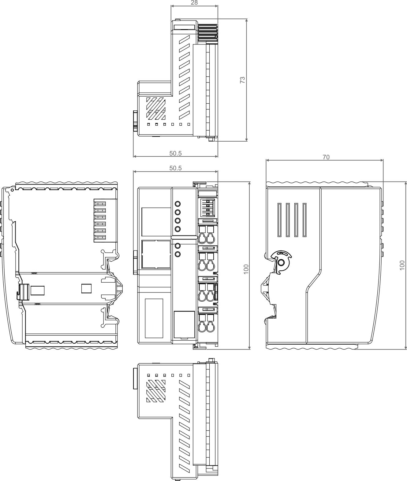
| Dimensions | 100mm x 70mm x 50.5mm |
| Weight | About 240g |
| Wiring Specifications | 0.2mm² ~ 1.5mm² |
| Wiring Method | Screwless |
| Installation | DIN-rail installation |
| Environmental & Regulatory |
|---|
| Operating Temperature | -10℃ ~ 55℃ |
| Storage Temperature | -20℃ ~ 85℃ |
| Ambient Humidity | 5% ~ 95% (non-condensing) |
| Air Pressure | ≥ 795 hPa (altitude ≤ 2000 m), compliant with IEC 61131-2 |
| Overvoltage Categories | I |
| Certifications | CE and RoHS |
| EtherCAT Port |
|---|
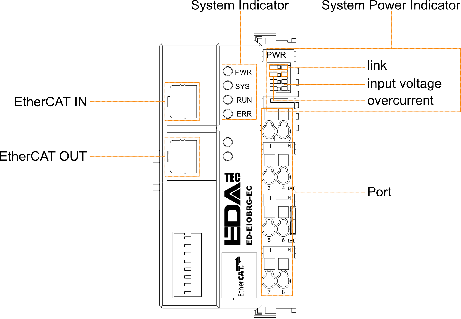
| EtherCAT IN | EtherCAT input port for access to the EtherCAT network, supporting to connect to EtherCAT master or the EtherCAT OUT of EtherCAT slave. |
| EtherCAT OUT | EtherCAT output port for connecting other EtherCAT devices on the same network segment, supporting to connect the EtherCAT IN of EtherCAT slave. |
| System Indicator |
|---|
| PWR | 2 x green power indicators, using to view the power status of coupler. |
| SYS | 1 x green system tip indicator, using to check the operational status of coupler. |
| RUN | 1 x green running indicator, using to check the running status of coupler. |
| ERR | 1 x red fault indicator, using to see if the coupler is malfunctioning. |
| System Power Indicator |
|---|
| Link | 1 x green link indicator, using to see if the connection of common terminal is normal. |
| Input Voltage | 1 x green input voltage indicator, using to see if the input voltage is normal. |
| Overcurrent | 1 x red overcurrent indicator, using to see if the coupler exceeds the maximum operating current. |
| Power Port |
|---|
| Pin No. | Description | Pin No. | Description |
| 1 | 24V SYS | 2 | 24V SYS |
| 3 | 24V Field | 4 | 24V Field |
| 5 | 0V Field | 6 | 0V Field |
| 7 | PE | 8 | PE |
Unit: mm
| Model | Description |
|---|
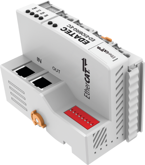
| ED-EIOBRG-EC | EtherCAT Coupler, 2 x EtherCAT Ports |
| Model | Description |
|---|
| ED-PLC2010 | EtherCAT Master based on CODESYS |
| Model | Description |
|---|
| ED-EIO8XP | 8-channel digital input module (PNP) |
| ED-EIO8XN | 8-channel digital input module (NPN) |
| ED-EIO16XP | 16-channel digital input module (PNP) |
| ED-EIO16XN | 16-channel digital input module (NPN) |
| ED-EIO8YP | 8-channel digital output module (PNP) |
| ED-EIO8YN | 8-channel digital output module (NPN) |
| ED-EIO16YP | 16-channel digital output module (PNP) |
| ED-EIO16YN | 16-channel digital output module (NPN) |
| ED-EIO4YR | 4-channel digital output module (Relay) |
| ED-EIO4ADV | 4-channel analog input module (voltage), -5~5V/0~10V/-10~10V, configurable |
| ED-EIO4ADA | 4-channel analog input module (current), 4-20mA/0-20mA, configurable |
| ED-EIO8ADA | 8-channel analog input module (current), 4-20mA/0-20mA, configurable |
| ED-EIO4AD | 4-channel analog input module (voltage/current mixed), -5~5V/0~10V/-10~10V/4-20mA/0-20mA, configurable |
| ED-EIO4DAV | 4-channel analog output module (voltage), -5~5V/0~10V/-10~10V, configurable |
| ED-EIO4DAA | 4-channel analog output module (current), 4-20mA/0-20mA, configurable |
| ED-EIO4RTD | 4-channel RTD Module |
| ED-EIO4TC | 4-channel TC Module |
| ED-EIO2HCD | 2-channel High Speed Counter Module |
| ED-EIOPWR | Power Expansion Supply Module |
| ED-EIOTERM | Bus End Cover |
TIP
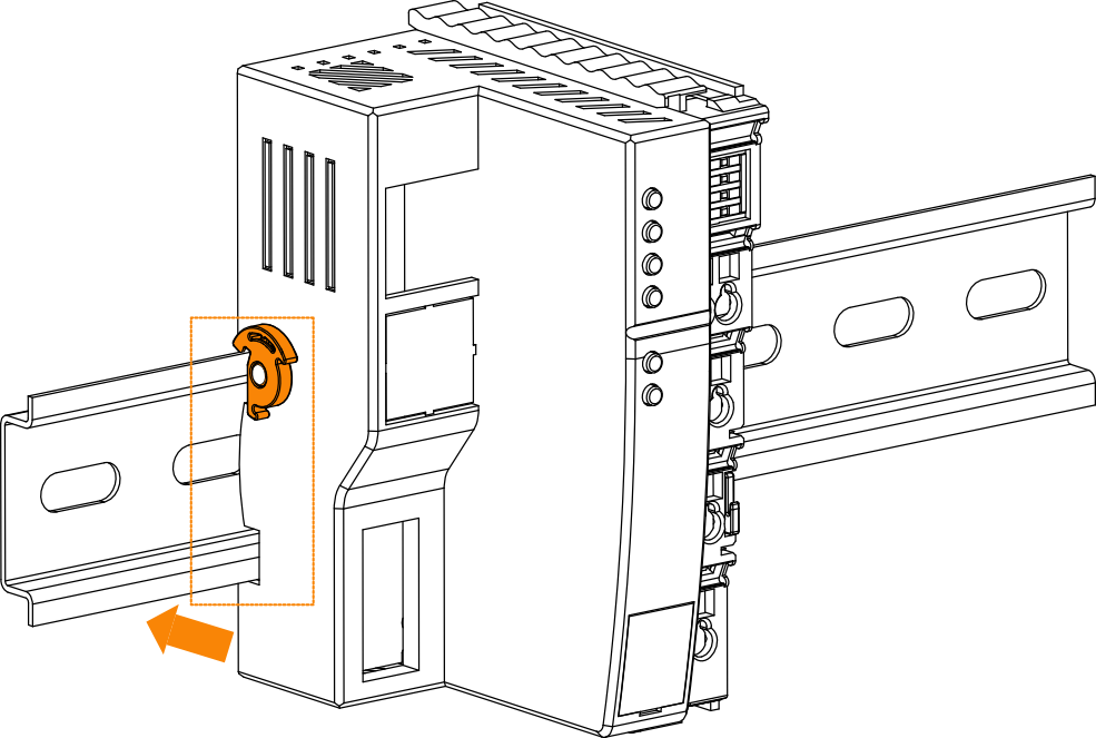
- DIN-rail is not included in the box, the following is intended as an installation illustration only.
- Before you start installing, please turn off the power to the coupler.
Step
Slip the notches on the back of the EtherCAT Coupler over the DIN-rail, then press it and push in the DIN snap pin to secure the EtherCAT Coupler to the DIN rail.
TIP
- Before you start installing, please turn off the power and disconnect the cable to the coupler.
Step
Hold the snap pin of the coupler by hand and then pull it out in the direction of the arrow to disengage the coupler from the DIN-rail.