3 Wiring Guide
3.1 Panel I/O
3.1.1 ADC
Taking ADC1 as an example, the wiring diagram of analog signal input is as follows:

3.1.2 DI
The ED-CM4IND contains 2 isolated DI interfaces. There are two wiring methods for the digital input signals, dry contact (passive) wiring and wet contact (active) wiring.
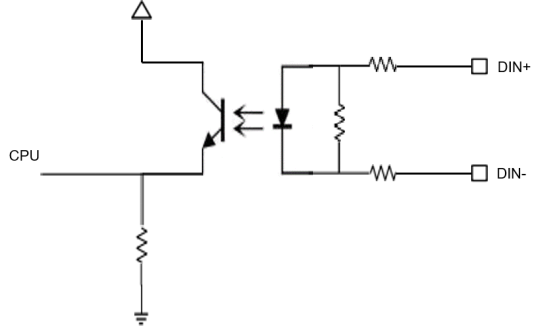
The digital signal input equivalent circuit is shown below:
3.1.2.1 Wet Contact
Wet contact wiring requires external power supply, the input is an active signal, the positive pole is connected to the device DIN+ port, the negative pole is connected to the device DIN- port.
- When the input
DIN+andDIN-are on and the level signal is greater than 3V, the internal optocoupler of the DI port is on, i.e., the module considers the input signal to be low. - When
DIN+andDIN-are disconnected, the internal optocoupler of DI port conducts, i.e. the module considers the input signal as high level.

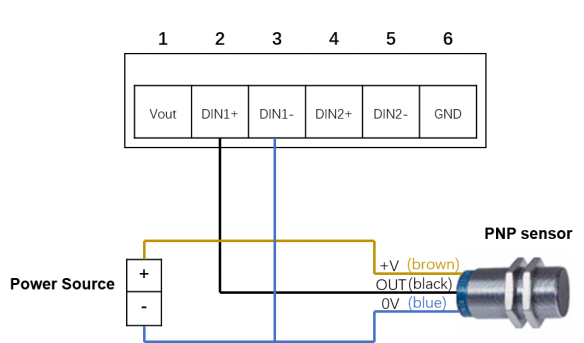
In the field of industrial control, three wire PNP type and NPN type sensors are the most common. Among the three wires, usually brown represents the positive electrode (VCC), blue represents the negative electrode (GND), and black represents the signal output terminal (OUT).
PNP type sensors are also known as source input mode sensors. When a signal is triggered, the OUT signal terminal outputs a high level.
The connection diagram of PNP type sensor is as follows.
If you do not use an external power supply to power the sensor, you can use the Vout provided by ED-CM4IND for power supply. The connection diagram for PNP type sensors using Vout power supply is as follows:
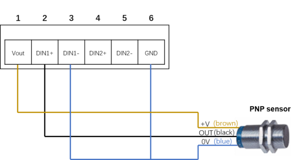
TIP
Vout can only provide 12V power output.
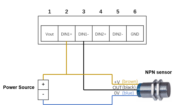
NPN type sensors are also known as sinking input mode sensors. When a signal is triggered, the OUT signal terminal outputs a low level.
The connection diagram of NPN type sensor is as follows.
If you do not use an external power supply to power the sensor, you can use the Vout provided by ED-CM4IND for power supply. The connection diagram for NPN type sensors using Vout power supply is as follows:
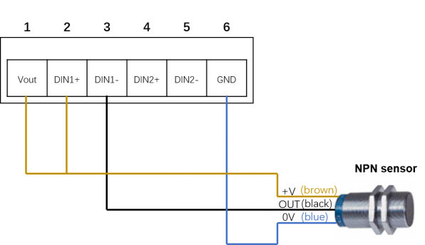
TIP
Vout can only provide 12V power output.
3.1.2.2 Dry Contact
The input signal of dry contact connection mode is passive switching signal. The change of input state can be detected by disconnecting or shorting the DI and COM port.

3.1.3 Realy
The relay output interfaces NC, COM, NO, correspond to the normally closed, common, and normally open of the relays respectively, and the relays of ED-CM4IND are double-knife, double-throw relays.
- When the control relay is closed, NO1 and NO2 are closed with respect to COM1 and COM2.
- When the control relay is popped open, NO1 and NO2 are both in the disconnected state relative to COM1 and COM2.
Taking an external DC load as an example, the wiring schematic of the relay is shown below:

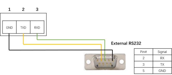
3.1.4 RS232
ED-CM4IND includes 1 RS232 port.
The wiring diagram of RS232 serial port is as follows:
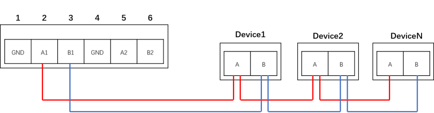
3.1.5 RS485
ED-CM4IND includes 2 RS485 ports.
Taking RS485-1 interface as an example, the wiring diagram is as follows:
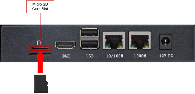
3.1.6 Micro SD Card slot
There is a Micro SD card slot on ED-CM4IND. Please insert the Micro SD card face up into the Micro SD card slot.
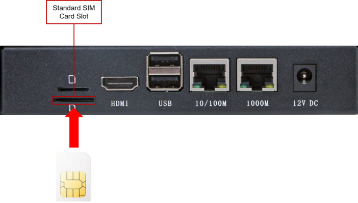
3.1.7 SIM Card Slot
The ED-CM4IND contains 1 standard SIM card slot, insert the standard SIM card chip end upwards into the SIM card slot.
3.2 Internal I/O
3.2.1 DSI
It is recommended that a 15-pin 1mm pitch single-sided FPC connector cable be used to connect to the DSI interface, with the metal contact side facing up and inserted in a direction perpendicular to the FPC connector, as shown in the figure below.
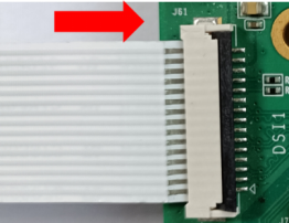
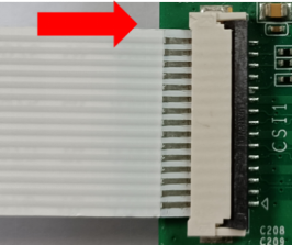
3.2.2 CSI
It is recommended that a 15-pin 1mm pitch single-sided FPC connector cable be used to connect to the CSI interface, with the metal contact side facing up and inserted in a direction perpendicular to the FPC connector, as shown in the figure below.