1 Product Overview
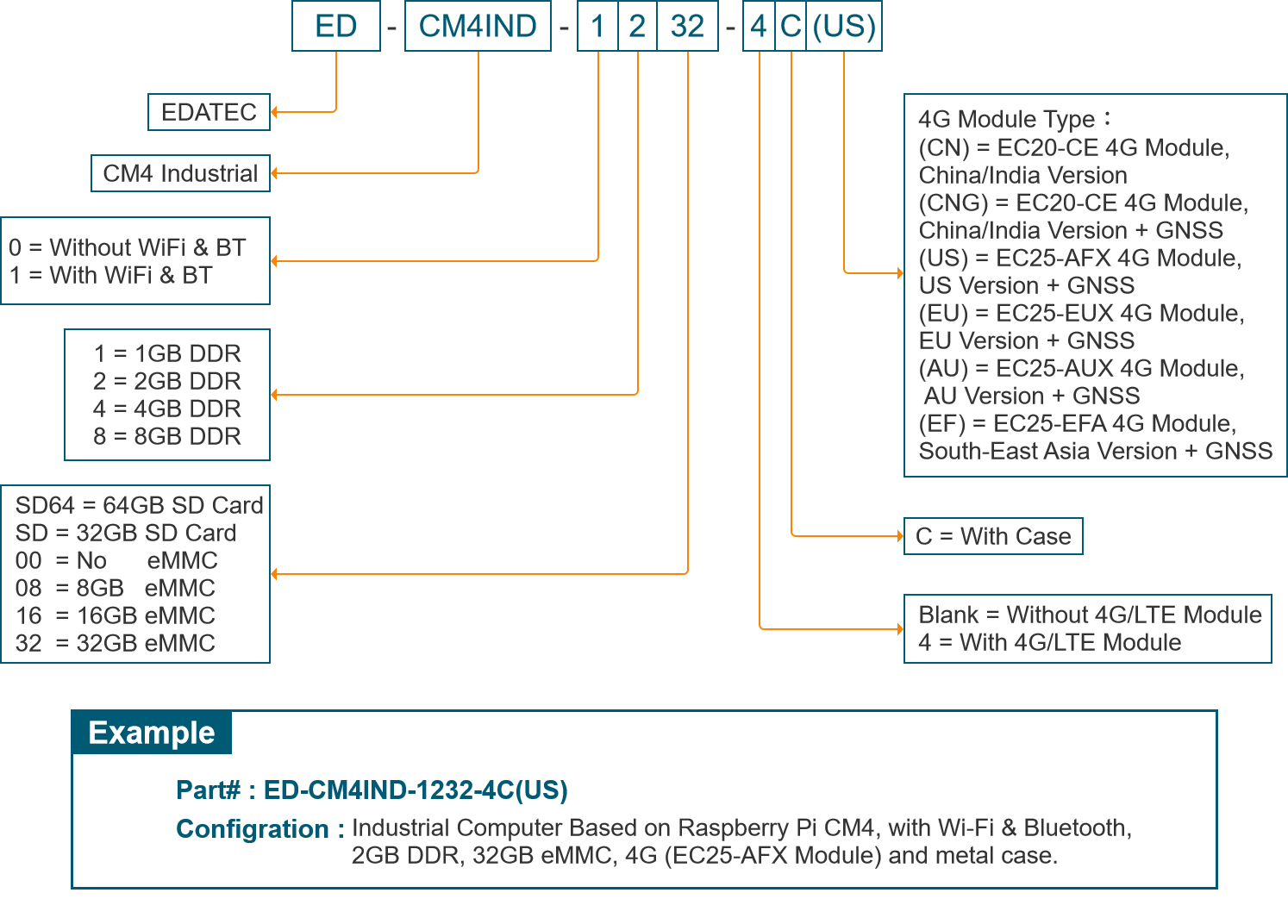
The ED-CM4IND is an industrial embedded computer based on the Raspberry Pi CM4. Depending on the application scenarios and user requirements, it offers a variety of configurations for RAM, eMMC, or SD card storage.
- The available RAM options include 1GB, 2GB, 4GB and 8GB.
- The eMMC options include 0GB, 8GB, 16GB and 32GB.
- The SD card options include 0GB and 32GB.
TIP
When purchasing the product, either an SD card or eMMC must be selected, and they cannot be chosen simultaneously.
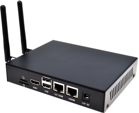
The ED-CM4IND provides commonly used interfaces such as HDMI, USB, RS232, RS485, DI, Relay, and ADC, and supports network connectivity via Wi-Fi, Ethernet, and 4G. Integrated with RTC and Buzzer, it enhances the product's ease of use and reliability, making it primarily suitable for industrial control and IoT applications.
1.1 Target Applications
- IoT Gateways
- Industrial Control
- Display Devices
- Smart Manufacturing
1.2 Specifications
| Function | Parameters |
|---|---|
| CPU | Broadcom BCM2711 quad-core Cortex-A72 (ARM v8) 64-bit SoC @ 1.5GHz |
| RAM | 1GB/2GB/4GB/8GB optional |
| eMMC | 0GB/8GB/16GB/32GB optional |
| Micro SD card | Supports 32GB SD card if CM4 without eMMC is selected |
| Extended storage | 1 x 4MB Serial Flash |
| Ethernet Interface | Dual Ethernet ports: 1 x 1000M port, 1 x 100M port |
| WiFi/BT | Dual-band WiFi (2.4GHz & 5GHz), Bluetooth 5.0 |
| 4G | 1 x PCIe 2.0 interface, supports optional 4G module |
| HDMI | 1 x Standard HDMI interface |
| USB | 2 x USB 2.0 interfaces, dual-layer Type-A connectors |
| RS485 | 2 x RS485 |
| RS232 | 1 x RS232 |
| ADC | 3 x ADC interfaces, 12-bit ADC |
| DI | 2 x DI |
| Relay | 1 x DPDT (Double Pole Double Throw) relay interface |
| Internal Reserved Interfaces | 1 x FPC HDMI, supports LCD screen expansion 1 x DSI, supports LCD screen expansion 2 x CSI, supports Raspberry Pi Camera expansion 2 x USB 2.0 Pin Header, supports USB 2.0 interface expansion 1 x Micro USB, for eMMC programming 1 x Serial (TTL), can be used as the default system console or configured as a standard serial port 1 x DC OUT, 5V@1A, can be used to power an expanded LCD screen 1 x Adjustable fan control interface 1 x Raspberry Pi 40-Pin GPIO 1 x RTC 1 x Buzzer |
| User Button | 1 x User button |
| Reset Button | 1 x Reset button |
| LED Indicators | Red (Power indicator), Green (System status indicator) |
| Operating System | Compatible with official Raspberry Pi OS, provides BSP support package, and supports APT online installation and updates |
| Input Power | V1.4: 9V ~ 36V DC V1.1~V1.3: 9V ~ 18V DC |
| Dimensions | 170mm (L) x 120mm (W) x 30mm (H) |
| Enclosure | Full metal enclosure, supports DIN rail mounting |
| Antenna Accessories | Supports optional WiFi/BT antenna and 4G antenna |
| Operating Temperature | -25°C to 50°C |
| Fan | 1x adjustable speed fan control interface |
1.3 System Diagram
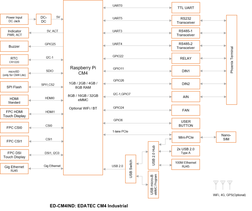
NoTE
The power input range for version V1.4 is 9V ~ 36V, while for versions V1.1 to V1.3, the power input range is 9V ~ 18V.
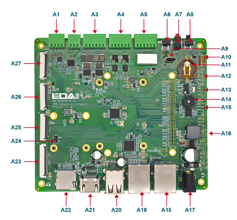
1.4 Functional Layout
| No. | Function | No. | Function |
|---|---|---|---|
| A1 | 3 × ADC | A15 | Debug serial port |
| A2 | 1 × RS232 | A16 | Custom GPIO Pin Header |
| A3 | 2 × RS485 | A17 | DC Power Socket |
| A4 | 2 × DI | A18 | 1000M Ethernet Port |
| A5 | 2 × Relay | A19 | 100M Ethernet Port |
| A6 | Reset Button | A20 | 2 × USB 2.0 |
| A7 | Power and Status Indicators | A21 | Standard HDMI Interface |
| A8 | User Button | A22 | Micro SD Card Slot |
| A9 | Micro USB Interface | A23 | HDMI FPC Interface |
| A10 | Fan Interface | A24 | 5V Power Output Interface |
| A11 | RTC Battery Base | A25 | DSI FPC Interface |
| A12 | USB6 Pin Header | A26 | CSI1 Interface |
| A13 | USB5 Pin Header | A27 | CSI0 Interface |
| A14 | Buzzer | - | - |
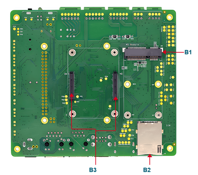
| No. | Function | No. | Function |
|---|---|---|---|
| B1 | Mini PCIe interface | B3 | CM4 Socket |
| B2 | Standard SIM Card Slot | -- | -- |
1.5 Packing List
- 1 x ED-CM4IND Unit
- [WiFi/BT Version - optional] 1 x 2.4GHz/5GHz WiFi/BT Antenna
- [4G Version - optional] 1 x 4G/LTE Antenna
1.6 Ordering Code