4 Internal Interface
4.1 SPI Flash
The ED-CM4IND expands a 4MB SPI Flash via SPI for user data storage. The SPI Flash is connected to the CM4's spi-1 bus, with the following pin definitions:
| Pin | Signal | CM4 Pinout |
|---|---|---|
| 1 | SPI_CS | GPIO16 |
| 2 | SPI_SCK | GPIO21 |
| 3 | SPI_MISO | GPIO19 |
| 4 | SPI_MOSI | GPIO20 |
4.2 RTC
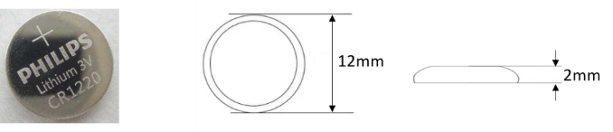
The ED-CM4IND integrates an RTC. For domestically sold versions, a CR1220 coin cell battery (RTC backup power) is pre-installed to ensure a reliable and uninterrupted clock, unaffected by power loss. The RTC clock chip is connected to the i2c-1 bus with a device address of 0x51.
i2c-1 Bus Pin Definition:
| Pin | Signal | CM4 Pinout |
|---|---|---|
| 1 | SDA1 | GPIO2 |
| 2 | SCL1 | GPIO3 |
NOTE
Some international logistics do not support battery shipments, so some devices may not include the CR1220 battery. Before using the RTC, ensure a CR1220 coin cell battery is installed on the motherboard.
4.3 Buzzer
The ED-CM4IND integrates a buzzer, controllable via GPIO. The pin definition is as follows:
| Pin | Signal | CM4 Pinout |
|---|---|---|
| 1 | BEEP | GPIO25 |
4.4 MIPI DSI
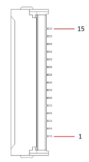
The ED-CM4IND includes one MIPI DSI interface, labeled "DSI1," supporting LCD screen expansion. The pin definitions are as follows:
 | Pin ID | Pin Name |
|---|---|---|
| 1 | GND | |
| 2 | DSI1_D0_N | |
| 3 | DSI1_D0_P | |
| 4 | GND | |
| 5 | DSI1_D1_N | |
| 6 | DSI1_D1_P | |
| 7 | GND | |
| 8 | DSI1_CLK_N | |
| 9 | DSI1_CLK_P | |
| 10 | GND | |
| 11 | SCL0 | |
| 12 | SDA0 | |
| 13 | GND | |
| 14 | 3V3 | |
| 15 | 3V3 |
4.5 MIPI CSI
The ED-CM4IND includes two MIPI CSI interfaces, labeled "CSI1" and "CSI0," supporting Raspberry Pi Camera expansion.
4.5.1 CSI0
The Pin definition are as follows:
| Pin ID | Pin Name |
|---|---|---|
| 1 | GND | |
| 2 | DSI1_D0_N | |
| 3 | DSI1_D0_P | |
| 4 | GND | |
| 5 | DSI1_D1_N | |
| 6 | DSI1_D1_P | |
| 7 | GND | |
| 8 | DSI1_CLK_N | |
| 9 | DSI1_CLK_P | |
| 10 | GND | |
| 11 | CAM_GPIO | |
| 12 | 无 | |
| 13 | ID_SC | |
| 14 | ID_SD | |
| 15 | 3V3 |
4.5.2 CSI1
The Pin definition are as follows:
| Pin ID | Pin Name |
|---|---|---|
| 1 | GND | |
| 2 | DSI1_D0_N | |
| 3 | DSI1_D0_P | |
| 4 | GND | |
| 5 | DSI1_D1_N | |
| 6 | DSI1_D1_P | |
| 7 | GND | |
| 8 | DSI1_CLK_N | |
| 9 | DSI1_CLK_P | |
| 10 | GND | |
| 11 | CAM_GPIO | |
| 12 | NC | |
| 13 | SCL0 | |
| 14 | SDA0 | |
| 15 | 3V3 |
4.6 FPC HDMI
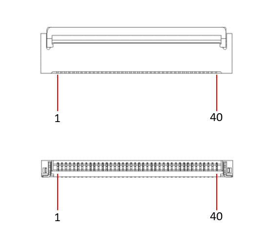
The ED-CM4IND includes one FPC HDMI interface, labeled "HDMI LCD," with reserved USB 2.0 touch signals and PWM backlight control signals, supporting HDMI touchscreens. A 40-pin 0.5mm pitch FPC cable is recommended for connecting LCD screens.
The Pin definition are as follows:
 | Pin ID | Pin Name | Pin ID | Pin Name |
|---|---|---|---|---|
| 1 | Y+ | 21 | GND | |
| 2 | X+ | 22 | HDMI1_CLKP | |
| 3 | Y- | 23 | HDMI1_CLKN | |
| 4 | X- | 24 | GND | |
| 5 | GND | 25 | BACKLIGHT_PWM | |
| 6 | USB_DP | 26 | GND | |
| 7 | USB_DM | 27 | GND | |
| 8 | GND | 28 | GND | |
| 9 | HDMI1_HPD | 29 | GND | |
| 10 | HDMI1_SCL | 30 | GND | |
| 11 | HDMI1_SDA | 31 | GND | |
| 12 | GND | 32 | LCD_PWR_EN | |
| 13 | HDMI1_TX2P | 33 | 5V | |
| 14 | HDMI1_TX2N | 34 | 5V | |
| 15 | GND | 35 | 5V | |
| 16 | HDMI1_TX1P | 36 | 5V | |
| 17 | HDMI1_TX1N | 37 | 5V | |
| 18 | GND | 38 | 5V | |
| 19 | HDMI1_TX0P | 39 | 5V | |
| 20 | HDMI1_TX0N | 40 | 5V |
4.7 40-PIN GPIO
The ED-CM4IND includes one 40-pin GPIO header, compatible with Raspberry Pi HAT, supporting various Raspberry Pi expansion accessories. The Pin definitions are as follows:
| Pin | Name | IO | Definition | Configured Function |
|---|---|---|---|---|
| 1 | 3V3 | O | 3.3V | -- |
| 2 | 5V | I/O | 5V | -- |
| 3 | PIN3 | I/O | GPIO2 | I2C1_SDA |
| 4 | 5V | I/O | 5V | -- |
| 5 | PN5 | I/O | GPIO3 | I2C1_SDL |
| 6 | GND | -- | GND | -- |
| 7 | PIN7 | I/O | GPIO4 | TXD3 |
| 8 | PIN8 | I/O | GPIO14 | TXD0 |
| 9 | GND | -- | GND | -- |
| 10 | PIN10 | I/O | GPIO15 | RXD0 |
| 11 | PIN11 | I/O | GPIO17 | GPIO17 |
| 12 | PIN12 | I/O | GPIO18 | BACKLIGHT_PWM |
| 13 | PIN13 | I/O | GPIO27 | GPIO27 |
| 14 | GND | -- | GND | -- |
| 15 | PIN15 | I/O | GPIO22 | RELAY |
| 16 | PIN16 | I/O | GPIO23 | LCD_PWR_EN |
| 17 | 3V3 | O | 3.3V | -- |
| 18 | PIN18 | I/O | GPIO24 | FAN_EN |
| 19 | PIN19 | I/O | GPIO10 | RST_4G |
| 20 | GND | -- | GND | -- |
| 21 | PIN21 | I/O | GPIO9 | RXD4 |
| 22 | PIN22 | I/O | GPIO25 | BEEP |
| 23 | PIN23 | I/O | GPIO11 | DIN1 |
| 24 | PIN24 | I/O | GPIO8 | TXD4 |
| 25 | GND | -- | GND | -- |
| 26 | PIN26 | I/O | GPIO7 | ADC_INT |
| 27 | PIN27 | I/O | GPIO0 | ID_SD |
| 28 | PIN28 | I/O | GPIO1 | ID_SC |
| 29 | PIN29 | I/O | GPIO5 | RXD3 |
| 30 | GND | -- | GND | -- |
| 31 | PIN31 | I/O | GPIO6 | USER BUTTON |
| 32 | PIN32 | GPIO12 | TXD5 | |
| 33 | PIN33 | I/O | GPIO13 | HDMI1_CLKN |
| 34 | GND | -- | GND | -- |
| 35 | PIN35 | I/O | GPIO19 | SPI_MISO |
| 36 | PIN36 | I/O | GPIO16 | SPI_CS |
| 37 | PIN37 | I/O | GPIO26 | DIN2 |
| 38 | PIN38 | I/O | GPIO20 | SPI_MOSI |
| 39 | GND | -- | GND | -- |
| 40 | PIN40 | I/O | GPIO21 | SPI_SCK |
NOTE
Some GPIO pins on the 40-pin header are pre-configured for onboard functions. Please check before use.
4.8 Mini PCIe Interface
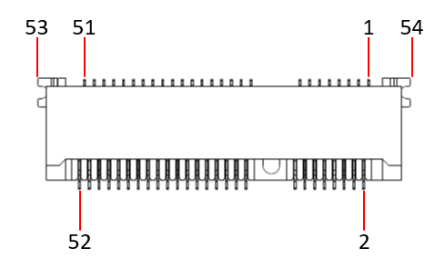
The ED-CM4IND includes one Mini PCIe interface, supporting 4G module expansion (optional). Pin Definitions are as follow:
 | Pin ID | Pin Name | Pin ID | Pin Name | Pin ID | Pin Name |
|---|---|---|---|---|---|---|
| 1 | NC | 21 | GND | 41 | 3V3 | |
| 2 | 3V3 | 22 | GPIO10 / PCIE_nRST | 42 | LED_WWAN | |
| 3 | NC | 23 | PCIE_RXN | 43 | GND | |
| 4 | GND | 24 | 3V3 | 44 | NC | |
| 5 | NC | 25 | PCIE_RXP | 45 | NC | |
| 6 | NC | 26 | GND | 46 | NC | |
| 7 | PCIE_CLK_nREQ | 27 | GND | 47 | NC | |
| 8 | USIM_VDD | 28 | NC | 48 | NC | |
| 9 | GND | 29 | GND | 49 | NC | |
| 10 | USIM_DATA | 30 | NC | 50 | GND | |
| 11 | GND | 31 | PCIE_TXN | 51 | NC | |
| 12 | USIM_CLK | 32 | NC | 52 | 3V3 | |
| 13 | PCIE_CLKP | 33 | PCIE_TXP | 53 | GND | |
| 14 | USIM_RST | 34 | GND | 54 | GND | |
| 15 | GND | 35 | GND | -- | -- | |
| 16 | NC | 36 | USB_DM | -- | -- | |
| 17 | NC | 37 | GND | -- | -- | |
| 18 | GND | 38 | USB_DP | -- | -- | |
| 19 | NC | 39 | 3V3 | -- | -- | |
| 20 | NC | 40 | GND | -- | -- |
4G Module Reset Pin Definition:
| Pin | Signal | CM4 Pinout |
|---|---|---|
| 1 | RST_4G | GPIO10 |
4.9 USB 2.0 Pin Header
The ED-CM4IND includes two USB 2.0 pin headers, labeled J44 and J63, with a 4-pin 2.54mm pitch. These can be used to expand USB 2.0 interfaces as needed. Pin Definitions are as follows:
| Pin ID | Pin Name |
|---|---|
| 1 | 5V |
| 2 | D- |
| 3 | D+ |
| 4 | GND |
4.10 UART Pin Header
The ED-CM4IND includes one UART pin header, labeled J58 and named "UART0." It is a TTL-level serial port with a 4-pin 2.54mm pitch, typically used as a debug serial port. Pin Definitions are as follows:
| Pin ID | Pin Name |
|---|---|
| 1 | 3.3V |
| 2 | GND |
| 3 | TXD0 |
| 4 | RXD0 |
4.11 2-PIN GPIO Pin Header
The ED-CM4IND provides one GPIO via a 2-pin 2.54mm pitch header, labeled J68 and connected to GPIO27 on the CM4. It can be configured for various purposes. Pin definitions are as follows:
| Pin ID | Pin Name |
|---|---|
| 1 | GND |
| 2 | GPIO27 |
4.12 Micro USB Interface
The ED-CM4IND includes one Micro USB interface, labeled J73 and named "USB PROGRAM," used for eMMC programming. Pin definitions are as follows:
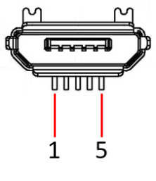 | Pin ID | Pin Name |
|---|---|---|
| 1 | 5V | |
| 2 | D- | |
| 3 | D+ | |
| 4 | NC | |
| 5 | GND |
4.13 5V 1A Output
The ED-CM4IND includes one 5V 1A power output interface, labeled J72, providing 5V 1A DC output for powering external LCD screens. Pin definitions are as follows:
| Pin ID | Pin Name |
|---|---|
| 1 | 5V |
| 2 | GND |
4.14 PoE Pin Header
The ED-CM4IND includes one PoE pin header for connecting PoE HAT modules. Pin definitions are as follows:
| Pin ID | Pin Name |
|---|---|
| 1 | VC1- |
| 2 | VC1+ |
| 3 | VC2- |
| 4 | VC2+ |
4.15 Fan Pin Header
The ED-CM4IND includes one fan control interface, labeled J67. Pin definitions are as follows:
| Pin ID | Pin Name |
|---|---|
| 1 | 5V (no pull-up) |
| 2 | 5V (bring pull) |
| 3 | FAN_EN |
| 4 | GND |
| 5 | GND |
TIP
FAN_EN is connected to GPIO24 on the CM4. By controlling GPIO24, the fan can be turned on/off and its speed adjusted.