3 Interfaces and Connectors
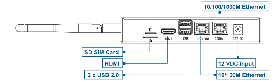
3.1 Front Panel
3.1.1 Power Input
The default input power for the ED-CM4IND is 12V. The power input range for hardware version V1.4 supports 9V to 36V, while hardware versions V1.1 to V1.3 support a power input range of 9V to 18V. The case is marked with "12V DC," and the connector is a standard 5.5*2.0 DC power socket with the center pin being positive and the outer sleeve negative.

3.1.2 1000M Ethernet
The ED-CM4IND includes one adaptive 10/100/1000M Ethernet interface, with the case marked as "1000M". It is recommended to use a Cat6 (Category 6) Ethernet cable when connecting to the network.
3.1.3 100M Ethernet
The ED-CM4IND includes one adaptive 10/100M Ethernet interface, with the case marked as "10/100M," used for network connectivity.
3.1.4 USB 2.0
The ED-CM4IND includes two USB 2.0 interfaces with Type-A connectors, supporting a maximum transmission rate of 480Mbit/s.
3.1.5 HDMI
The ED-CM4IND is equipped with one standard HDMI interface, featuring a Type-A connector, designed for connecting HDMI displays and supporting 4Kp60 resolution.
3.1.6 Micro SD Card Slot
The ED-CM4IND contains one Micro SD card slot for installing a Micro SD card, enabling system booting from the SD card.
NOTE
The Micro SD card is only required when using the CM4 Lite (without eMMC) core module to boot the system. If a CM4 module with eMMC is selected, the Micro SD card slot is unavailable.
3.1.7 SIM Card Slot
The ED-CM4IND includes one standard SIM card slot, supporting the optional 4G LTE module.
The size differences between a standard SIM card, Micro SIM card, and Nano SIM card are as follows: 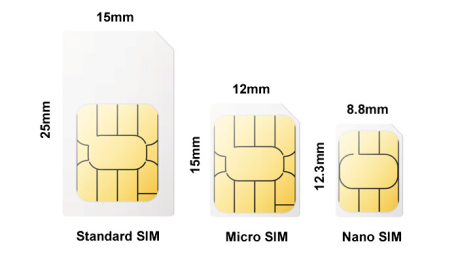
3.2 Rear Panel
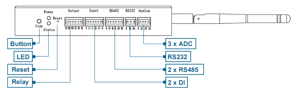
3.2.1 Indicators
The ED-CM4IND includes two indicators: a red LED for the Power indicator and a green LED for the Status indicator.
- Power Indicator: Used to check the device's power status.
- Status Indicator: Used to check the device's operational status.
| Indicator | Status | Description |
|---|---|---|
| Power | On | The device has been powered on. |
| Blink | Power supply of the device is abnormal, please stop the power supply immediately. | |
| Off | The device is not powered on. | |
| Status | Blink | The system started successfully and is reading and writing data. |
| Off | The device is not powered on or does not read and write data. |
3.2.2 Buttons
The ED-CM4IND includes two buttons: a Reset button and a User button.
3.2.2.1 RESET Button
The Reset button is a hidden button, marked as "Reset" on the case. Pressing the Reset button will reset the device.
3.2.2.2 User Button
The User button is marked as "User" on the case and is connected to the GPIO6 pin of the CM4 chip. By default, it is in a high-level state. When pressed, the pin goes to a low-level state, supporting user-defined functionality.
User Button Pin Definition:
| Pin | Signal | CM4 Pinout |
|---|---|---|
| 1 | User Button | GPIO6 |
3.2.3 ADC
The ED-CM4IND includes three ADC interfaces, communicating with the ADC acquisition chip via the i2c-1 bus. It uses a 2.5mm pitch Phoenix terminal, with the pin definitions as follows:
 | Pin ID | Pin Name |
|---|---|---|
| 1 | GND | |
| 2 | ADC1 | |
| 3 | ADC2 | |
| 4 | ADC3 |
3.2.4 RS232
The ED-CM4IND includes one RS232 serial port, using a 2.5mm pitch Phoenix terminal, corresponding to UART5 on the CM4. The device file is /dev/ttyAMA5.
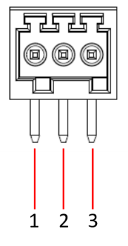 | |
| Pin ID | Pin Name |
|---|---|
| 1 | GND |
| 2 | TXD |
| 3 | RXD |
RS232 Pin Mapping to CM4 UART5:
| Pin | Signal | CM4 Pinout |
|---|---|---|
| 1 | TXD5 | UART5_TX/GPIO12 |
| 2 | RXD5 | UART4_RX/GPIO13 |
3.2.5 RS485
The ED-CM4IND includes two RS485 interfaces, using a 2.5mm pitch Phoenix terminal, with the pin definitions as follows:
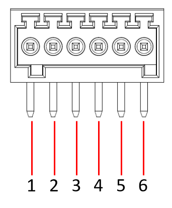 | Pin ID | Pin Name |
|---|---|---|
| 1 | GND | |
| 2 | 485-1_A | |
| 3 | 485-1_B | |
| 4 | GND | |
| 5 | 485-2_A | |
| 6 | 485-2_B |
RS485-1 Pin Mapping to CM4 UART4, the device file is /dev/ttyAMA4.
| Pin | Signal | CM4 Pinout |
|---|---|---|
| 1 | TXD4 | UART4_TX/GPIO8 |
| 2 | RXD4 | UART4_RX/GPIO9 |
RS485-2 Pin Mapping to CM4 UART3, the device file is /dev/ttyAMA3.
| Pin | Signal | CM4 Pinout |
|---|---|---|
| 1 | TXD3 | UART3_TX/GPIO4 |
| 2 | RXD3 | UART4_RX/GPIO5 |
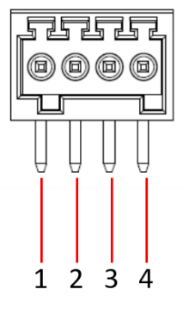
3.2.6 DI
The ED-CM4IND includes two isolated DI interfaces, using a 2.5mm pitch Phoenix terminal, with the pin definitions as follows:
| Pin ID | Pin Name |
|---|---|---|
| 1 | 12VIN | |
| 2 | DIN1+ | |
| 3 | DIN1- | |
| 4 | DIN2+ | |
| 5 | DIN2- | |
| 6 | GND |
DI Pin Mapping to CM4 GPIO are as follows:
| Pin | Signal | CM4 Pinout |
|---|---|---|
| 1 | DIN1 | GPIO11 |
| 2 | DIN2 | GPIO26 |
3.2.7 Relay
The ED-CM4IND includes one double-pole double-throw (DPDT) relay interface, using a 2.5mm pitch Phoenix terminal. The relay is controlled by the GPIO22 pin, with high and low levels determining its state. By default, it is normally closed (NC), with COM1 and NC1 connected, and COM2 and NC2 connected. When GPIO22 is high, the relay opens, connecting COM1 to NO1 and COM2 to NO2.
| Pin ID | Pin Name |
|---|---|---|
| 1 | NC2 | |
| 2 | COM2 | |
| 3 | NO2 | |
| 4 | NC1 | |
| 5 | COM1 | |
| 6 | NO1 |
Relay Control Pin definition:
| Pin | Signal | CM4 Pinout |
|---|---|---|
| 1 | RELAY | GPIO22 |
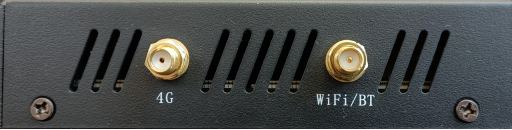
3.2.8 Antenna Interfaces
The ED-CM4IND includes up to two standard SMA antenna interfaces, for connecting the 4G antenna and the WiFi/BT antenna.