2 Installing Components
This chapter describes how to install optional components.
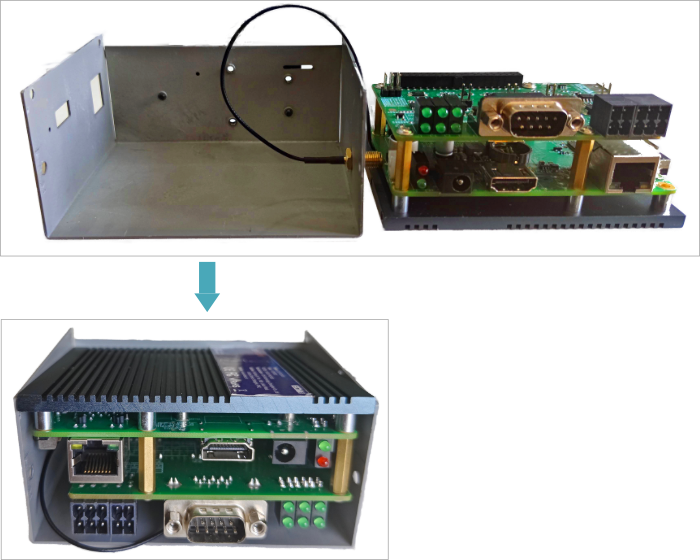
2.1 Opening and closing the device case
If the user needs to open the device case, refer to the following to do so.
2.1.1 Open device case
Preparation:
A cross screwdriver has been prepared.
Steps:
- Pull out the default configuration of phoenix connector.
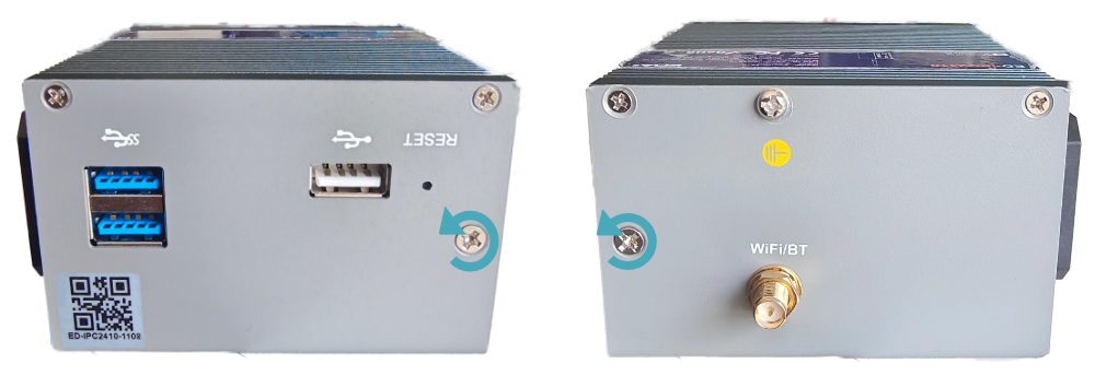
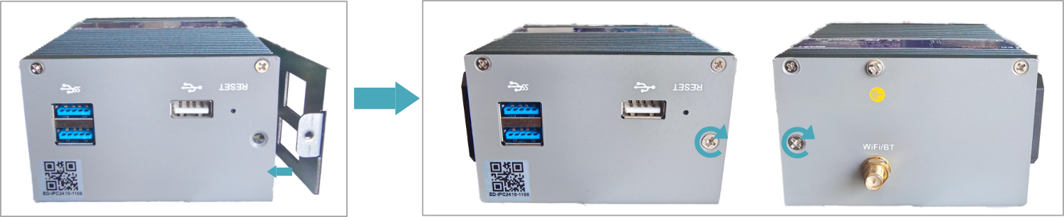
- Use a screwdriver to loosen two M3 screws on two sides counterclockwise,as shown in the figure below.
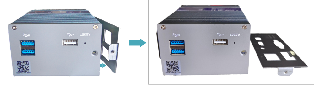
- Remove the front cover to the right, as shown in the figure below.
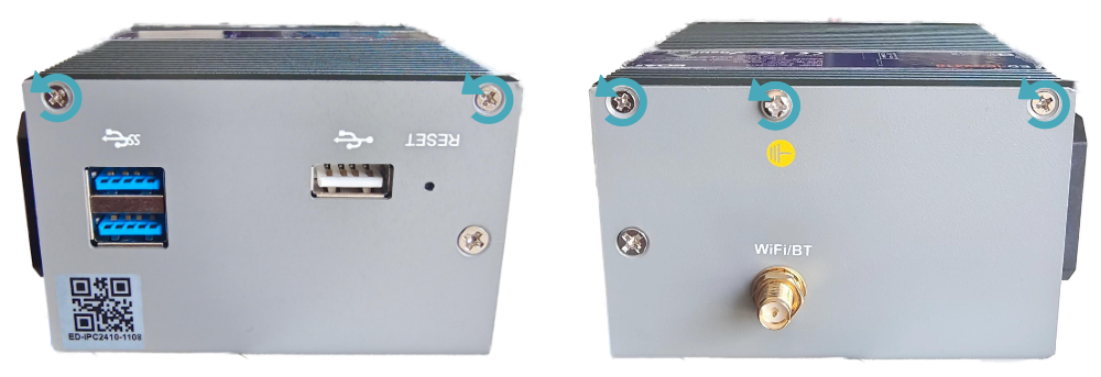
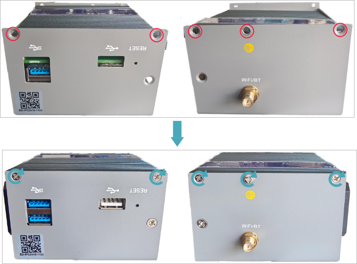
- Use a screwdriver to loosen four M2.5 screws and one grounding screw on two sides counterclockwise, as shown in the figure below.
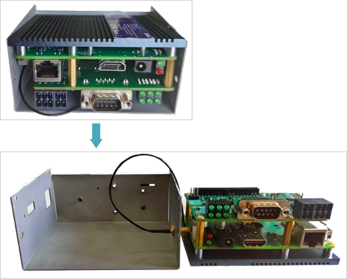
- Remove the upper cover upward and turn it to the antenna port side, as shown in the figure below.
2.1.2 Close Device Case
Preparation:
A cross screwdriver has been prepared.
Steps:
- Turn the upper cover downwards, align the ports on PCBA with the ports on each side panel and close the upper cover.
- Align the screw holes on the upper and side panels, and use a screwdriver to tighten four M2.5 screws and one grounding screw on two sides clockwise, as shown in the following figure.
- Align the ports on PCBA with the ports on the front panel, insert the front cover, and then use a screwdriver to fasten two M3 screws clockwise, as shown in the following figure.
- Plug in the default configuration of phoenix connector.
2.2 Installing Other Components
If the selected ED-IPC2400 series device includes Wi-Fi functions, the antenna need to be installed before using the device.
2.2.1 Install Antenna
Preparation:
The corresponding antennas have been obtained from the packaging box.
Steps:
- Locate the antenna port where the antenna is to be installed, as shown in the figure below.
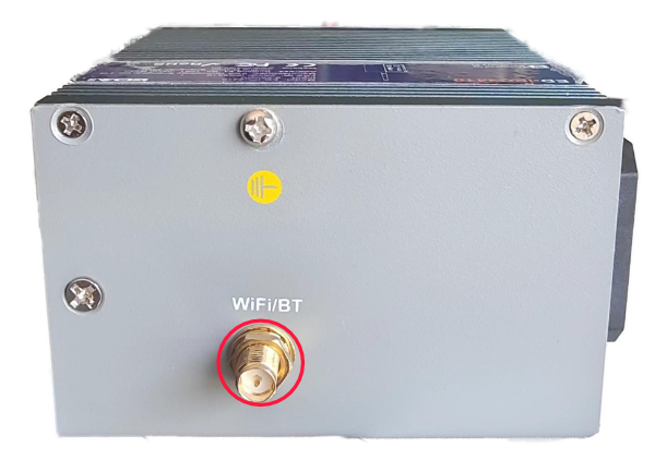
- Align the ports on both sides of the device and the antenna, and tighten them clockwise to ensure that they will not fall off.
2.2.2 Install Micro SD Card
Preparation:
The Micro SD card to be used has been obtained.
Steps:
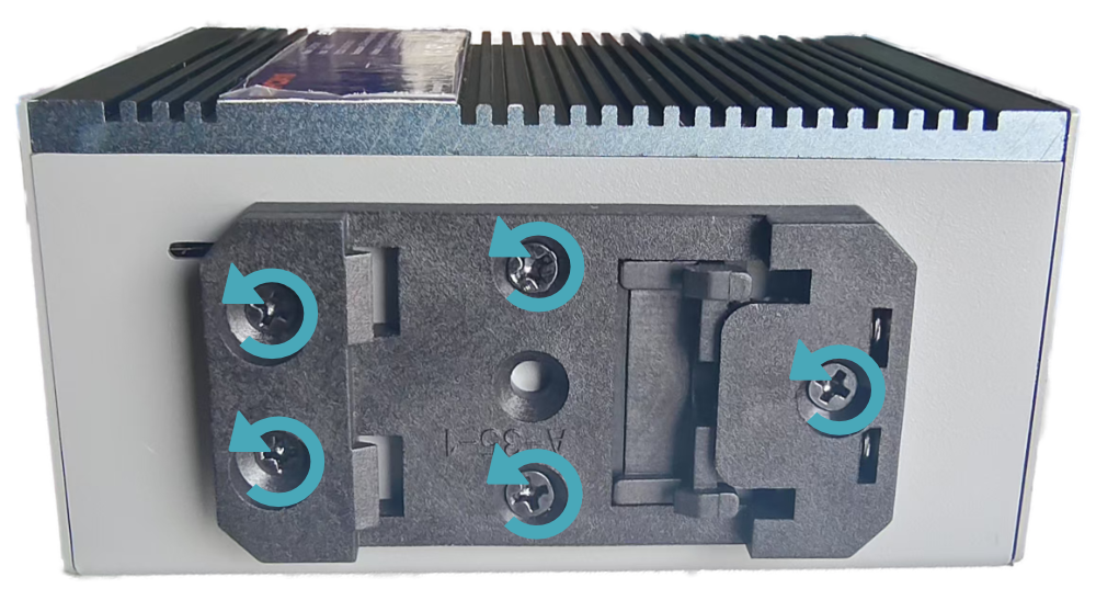
- Use a cross screwdriver to loosen 5 screws on the DIN-rail bracket counterclockwise and remove the default DIN-Rail bracket. As shown in the figure below.
- Locate the Micro SD card slot where the Micro SD is to be installed, as shown in the red box below.
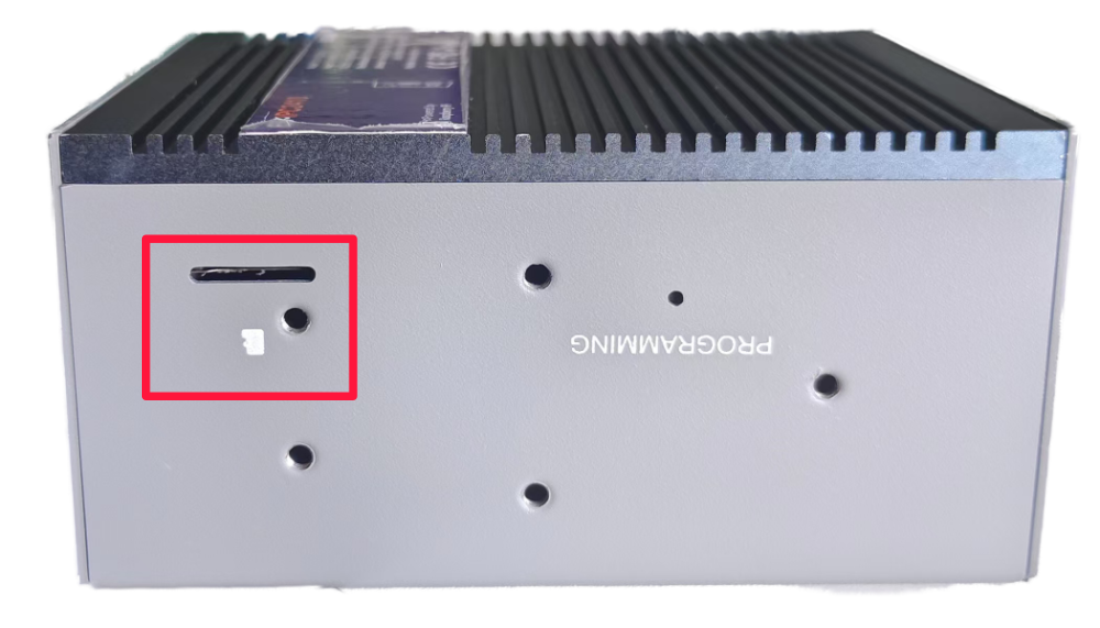
- Insert the Micro SD card with the contact side down into the corresponding card slot, and hear a sound to indicate that the installation is complete.

- Install the DIN-Rail bracket onto the device case.