1 Hardware Manual
This chapter introduces the product overview, packing list, appearance, button, indicator and interface.
1.1 Overview
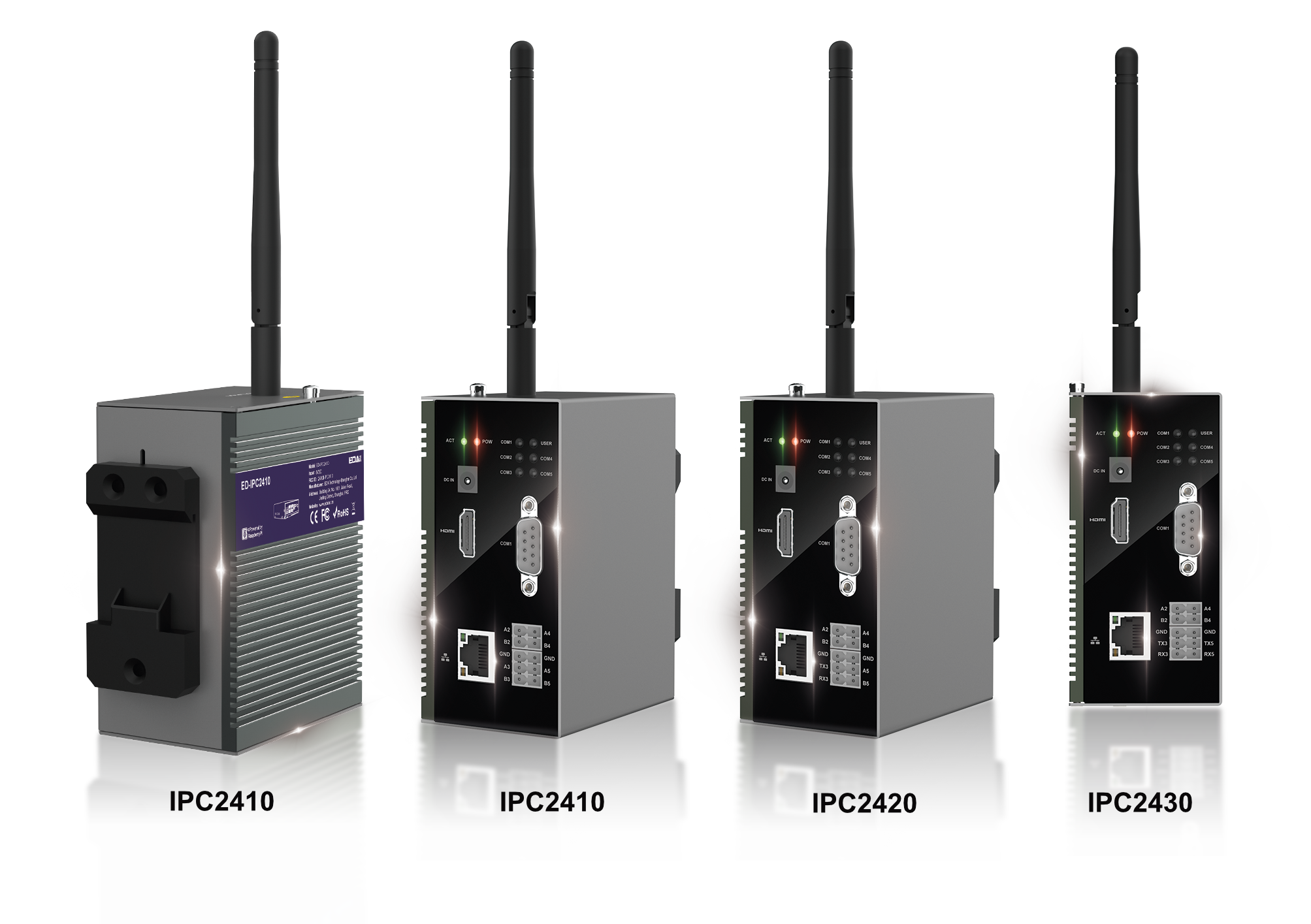
ED-IPC2400 series is an industrial computer based on Raspberry Pi CM4. According to different application scenarios and user needs, different specifications of RAM and eMMC computer systems can be selected.
- RAM can choose 1GB、2GB、4GB and 8GB.
- eMMC can choose 8GB、16GB and 32GB.
ED-IPC2400 series includes three models, ED-IPC2410, ED-IPC2420 and ED-IPC2430, which provide common interfaces such as HDMI, USB, Ethernet, RS232 and RS485, and support access to the network through Wi-Fi and Ethernet. It integrates RTC, EEPROM and encryption chip, providing the ease of use and reliability of the product, which is mainly used in industrial control and IOT.
1.2 Packing List
- 1x ED-IPC2400 Unit
- [optional Wi-Fi/BT version] 1x 2.4GHz/5GHz Wi-Fi/BT Antenna
1.3 Appearance
Introducing the functions and definitions of interfaces on each panel.
1.3.1 Front Panel
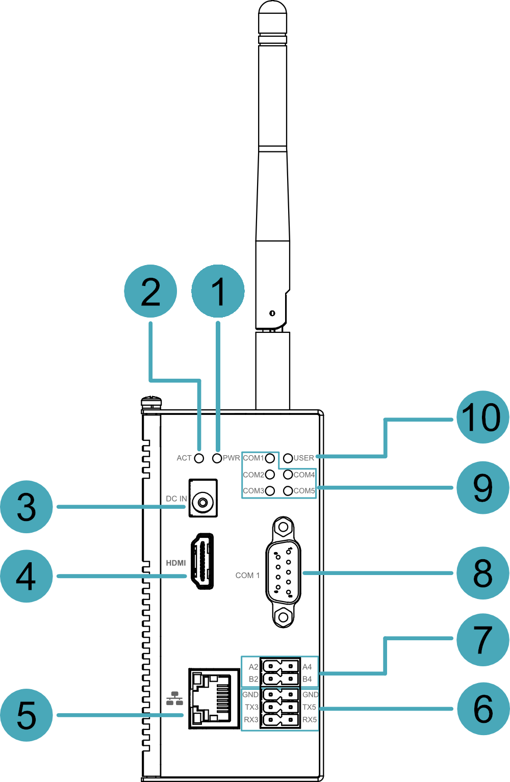
Introducing the front panel interface types and definitions.
ED-IPC2410

| NO. | Function Definition |
|---|---|
| 1 | 1 x red power indicator, which is used to check the status of device power-on and power-off. |
| 2 | 1 x green system status indicator, which is used to check the working status of device. |
| 3 | 1 x DC input, DC Jack connector. It supports 9V~28V input. |
| 4 | 1 x HDMI port, type A connector, which is compatibles with HDMI2.0 standard and supports 4K 60Hz. It supports to connect a displayer. |
| 5 | 1 x 10/100/1000M adaptive ethernet port, RJ45 connector, with led indicator. It can be used to access the network. |
| 6 | 2 x RS485 ports, 6-Pin 3.5mm spacing phoenix terminal, which is used to connect the third-party control equipment. |
| 7 | 2 x RS485 ports, 4-Pin 3.5mm spacing phoenix terminal, which is used to connect the third-party control equipment. |
| 8 | 1 x RS232 port, DB9 male terminal, using pins 2, 3 and 5 of the terminal, the corresponding signal is defined as RX/TX/GND. |
| 9 | 5 x green UART port indicator, which is used to check the communication status of UART port. |
| 10 | 1 x green user indicator, user can customize a status according to actual application. |
ED-IPC2420

| NO. | Function Definition |
|---|---|
| 1 | 1 x red power indicator, which is used to check the status of device power-on and power-off. |
| 2 | 1 x green system status indicator, which is used to check the working status of device. |
| 3 | 1 x DC input, DC Jack connector. It supports 9V~28V input. |
| 4 | 1 x HDMI port, type A connector, which is compatibles with HDMI2.0 standard and supports 4K 60Hz. It supports to connect a displayer. |
| 5 | 1 x 10/100/1000M adaptive ethernet port, RJ45 connector, with led indicator. It can be used to access the network. |
| 6 | 1 x RS485 port, 1 x RS232 port, 6-Pin 3.5mm spacing phoenix terminal, which is used to connect the third-party control equipment. |
| 7 | 2 x RS485 ports, 4-Pin 3.5mm spacing phoenix terminal, which is used to connect the third-party control equipment. |
| 8 | 1 x RS232 port, DB9 male terminal, using pins 2, 3 and 5 of the terminal, the corresponding signal is defined as RX/TX/GND. |
| 9 | 5 x green UART port indicator, which is used to check the communication status of UART port. |
| 10 | 1 x green user indicator, user can customize a status according to actual application. |
ED-IPC2430
| NO. | Function Definition |
|---|---|
| 1 | 1 x red power indicator, which is used to check the status of device power-on and power-off. |
| 2 | 1 x green system status indicator, which is used to check the working status of device. |
| 3 | 1 x DC input, DC Jack connector. It supports 9V~28V input. |
| 4 | 1 x HDMI port, type A connector, which is compatibles with HDMI2.0 standard and supports 4K 60Hz. It supports to connect a displayer. |
| 5 | 1 x 10/100/1000M adaptive ethernet port, RJ45 connector, with led indicator. It can be used to access the network. |
| 6 | 2 x RS232 ports, 6-Pin 3.5mm spacing phoenix terminal, which is used to connect the third-party control equipment. |
| 7 | 2 x RS485 ports, 4-Pin 3.5mm spacing phoenix terminal, which is used to connect the third-party control equipment. |
| 8 | 1 x RS232 port, DB9 male terminal, using pins 2, 3 and 5 of the terminal, the corresponding signal is defined as RX/TX/GND. |
| 9 | 5 x green UART port indicator, which is used to check the communication status of UART port. |
| 10 | 1 x green user indicator, user can customize a status according to actual application. |
1.3.2 Rear Panel
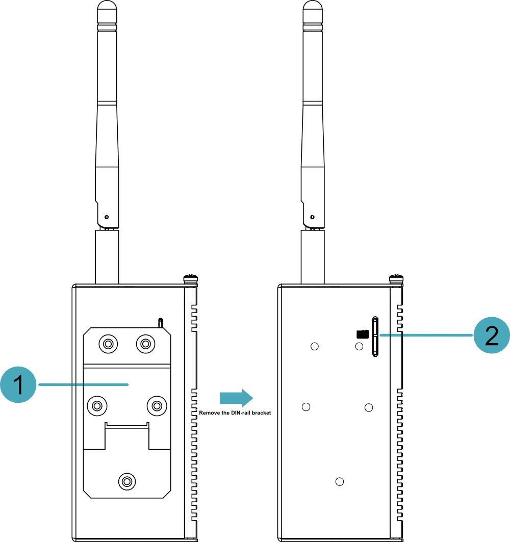
Introducing the types and definitions of the rear panel interface.
| NO. | Function Definition |
|---|---|
| 1 | 1 x DIN-rail bracket, install ED-IPC2400 Unit on the DIN-rail through the bracket. |
| 2 | 1 x Micro-SD card slot, it supports the installation of SD card for storing user data. |
1.3.3 Side Panel
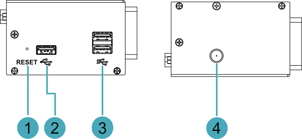
Introducing the types and definitions of side panel interfaces.
| NO. | Function Definition |
|---|---|
| 1 | 1 x Reset button, hidden button, press the button to restart the device. |
| 2 | 1 x USB 2.0 port, type A connector, each channel supports up to 480Mbps. |
| 3 | 2 x USB 3.0 ports, type A connector, each channel supports up to 5Gbps. |
| 4 | 1 x Wi-Fi/BT antenna port, SMA connector, which can connect to Wi-Fi/BT antenna. |
1.4 Button
ED-IPC2400 series device includes a RESET button, which is a hidden button, and the silkscreen on the case is "RESET". Pressing the RESET button will reset the device.
1.5 Indicator
Introducing the various statuses and meanings of indicators contained in ED-IPC2400 series device.
| Indicator | Status | Description |
|---|---|---|
| PWR | On | The device has been powered on. |
| Blink | Power supply of the device is abnormal, please stop the power supply immediately. | |
| Off | The device is not powered on. | |
| ACT | Blink | The system started successfully and is reading and writing data. |
| Off | The device is not powered on or does not read and write data. | |
| USER | On | User can customize a status according to actual application. |
| Off | The device is not powered on or not defined by the user, and the default status is off. | |
| Yellow indicator for Ethernet port | On | The data transmission is abnormal. |
| Blink | Data is being transmitted over the Ethernet port. | |
| Off | The Ethernet connection is not set up. | |
| Green indicator for Ethernet port | On | The Ethernet connection is in the normal state. |
| Blink | The Ethernet connection is abnormal. | |
| Off | The Ethernet connection is not set up. | |
| COM1~COM5 | On/Blink | Data is being transmitted. |
| Off | The device is not powered on or there is no data transmission. |
1.6 Interface
Introducing the definition and function of each interface in the product.
1.6.1 SD Card Slot
The silkscreen on the case of Micro SD card slot is " ", which is used to install SD card for storing user data.
1.6.2 Power Supply Interface
The ED-IPC2400 series device includes one power input, DC Jack connector. It supports 9V~28V input, and the silkscreen of port is "DC IN".
1.6.3 RS485/RS232 Interface
ED-IPC2400 series devices include 2~4 RS485 ports and 1~3 RS232 ports. Different product models correspond to different numbers of RS485 and RS232 ports:
- ED-IPC2410:4 x RS485、1x RS232
- ED-IPC2420:3 x RS485、2x RS232
- ED-IPC2430:2 x RS485、3 x RS232
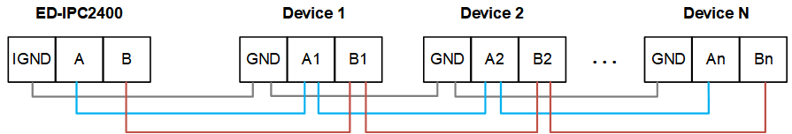
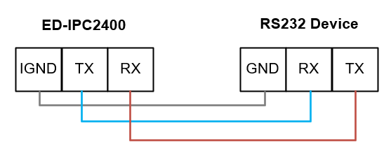
The silkscreen of RS485 single port is "GND/A/B". The silkscreen of RS232 single port is "GND/TX/RX", and the spacing of the terminals is 3.5mm.
Pin Definition - DB9 Terminal
Terminal pins are defined as follows:
 | Pin ID | Pin Name |
|---|---|---|
| 1 | NC | |
| 2 | RS232_TXD0 | |
| 3 | RS232_RXD0 | |
| 4 | NC | |
| 5 | GND | |
| 6 | NC | |
| 7 | NC | |
| 8 | NC | |
| 9 | NC |
| Signal | CM4 GPIO Name | CM4 Pin Out |
|---|---|---|
| RS232_TXD0 | GPIO14 | UART0_TXD |
| RS232_RXD0 | GPIO15 | UART0_RXD |
Pin Definition - Phoenix Terminal
Terminal pins are defined as follows:
 | Pin ID | Pin Name |
|---|---|---|
| 1 | RS485-4_A | |
| 2 | RS485-2_A | |
| 3 | RS485-4_B | |
| 4 | RS485-2_B | |
| 5 | GND | |
| 6 | GND | |
| 7 | RS232-5_TX or RS485-5_A | |
| 8 | RS232-3_TX or RS485-3_A | |
| 9 | RS232-5_RX or RS485-5_B | |
| 10 | RS232-3_RX or RS485-3_B |
The pin names of CM4 corresponding to RS485/RS232 interface are as follows:
| Signal | CM4 GPIO Name | CM4 Pin Out |
|---|---|---|
| RS485-4_A | GPIO8 | UART4_TXD |
| RS485-2_A | GPIO12 | UART5_TXD |
| RS485-4_B | GPIO9 | UART4_RXD |
| RS485-2_B | GPIO13 | UART5_RXD |
| RS232-5_TX or RS485-5_A | GPIO4 | UART3_TXD |
| RS232-3_TX or RS485-3_A | GPIO0 | UART2_TXD |
| RS232-5_RX or RS485-5_B | GPIO5 | UART3_RXD |
| RS232-3_RX or RS485-3_B | GPIO1 | UART2_RXD |
Connecting Cables
Schematic diagram of RS485 wires is as follows:
Schematic diagram of RS232 wires is as follows:
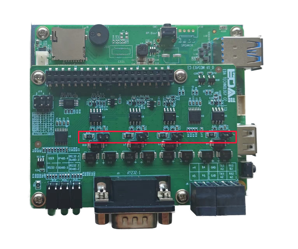
RS485 terminal resistance configuration
ED-IPC2400 device includes 2~4 RS485 ports, 120R jumper resistor is reserved between A and B of RS485 line, inserting jumper cap can enable this jumper resistor. The 120R termination resistor function is disabled when the jumper cap is not connected in the default state. The positions of the jumper resistor in the PCBA is as follows: J24, J25, J26 and J27 (red box location).
The corresponding relationship between 120R terminal resistance and serial port is as follows:
| Location in PCBA | Corresponding COM port | The specific location of the corresponding COM |
|---|---|---|
| J24 | COM2 | 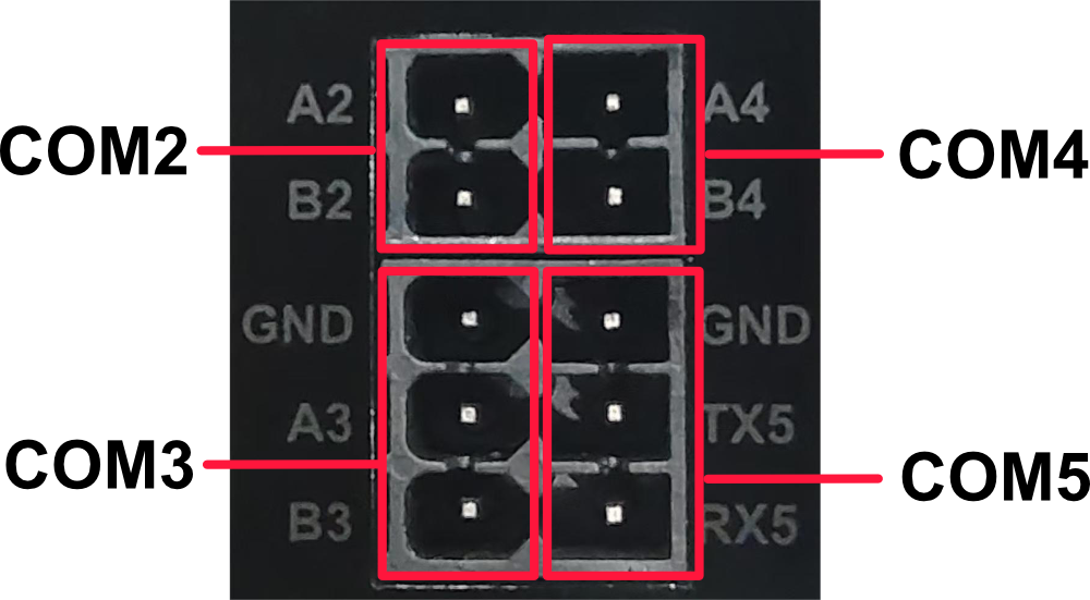 |
| J25 | COM4 | |
| J26 | COM3 | |
| J27 | COM5 |
TIP
You need to open the device case to view the position of 120R jumper resistor. For detailed operations, please refer to 2.1.1 Open Device Case.
1.6.4 1000M Ethernet Interface
The ED-IPC2400 device includes one adaptive 10/100/1000M Ethernet port, and the silkscreen is " ". The connector is RJ45, which is used to access the Ethernet. The pins corresponding to the terminals are defined as follows:
 | Pin ID | Pin Name |
|---|---|---|
| 1 | TX4- | |
| 2 | TX4+ | |
| 3 | TX3- | |
| 4 | TX3+ | |
| 5 | TX2- | |
| 6 | TX2+ | |
| 7 | TX1- | |
| 8 | TX1+ |
1.6.5 HDMI Interface
ED-IPC2400 series device includes one HDMI port, the silkscreen is "HDMI". The connector is type A HDMI, which can connect to an HDMI display and supports up to 4Kp60.
1.6.6 USB 2.0 Interface
ED-IPC2400 series device includes one USB2.0 port, the silkscreen is " ". The connector is type A USB, which can connect to standard USB 2.0 peripherals and supports up to 480Mbps.
1.6.7 USB 3.0 Interface
ED-IPC2400 series device includes 2 USB3.0 ports, the silkscreen is "". The connector is type A USB, which can connect to standard USB 3.0 peripherals and supports up to 5Gbps.
1.6.8 Antenna Interface
The ED-IPC2400 series device includes up to one SMA antenna port, the silkscreen is "WiFi/BT" and it can be connected to the Wi-Fi/BT antenna.
1.6.9 Motherboard Interface
Introducing the interfaces reserved in the ED-IPC2400 series device, which can be obtained only after the device case is opened( For detailed operations, please refer to 2.1.1 Open Device Case ), and can be expanded according to actual needs.
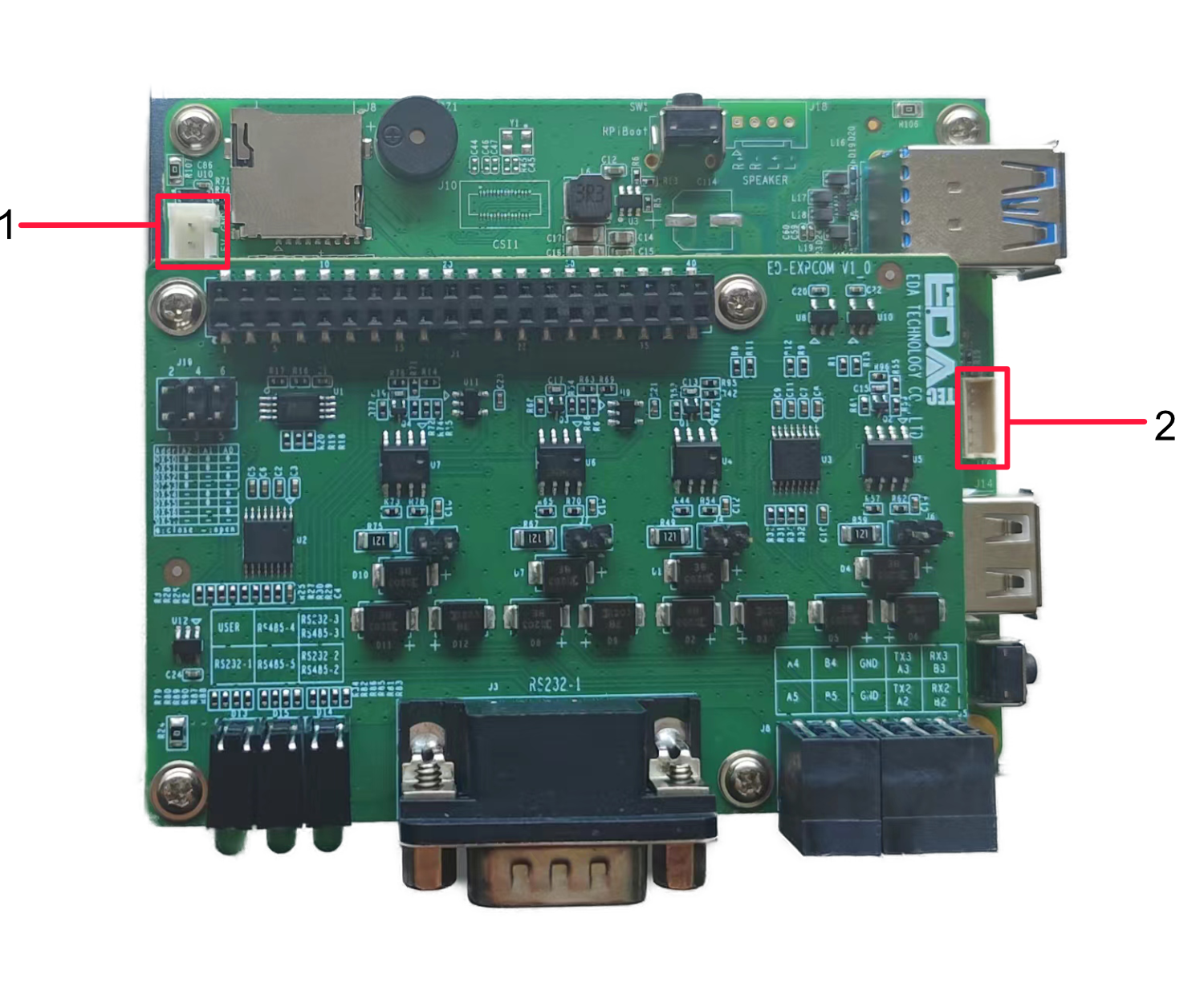
| NO. | Function |
|---|---|
| 1 | 5V 1A Output |
| 2 | USB 2.0 Pin Header |
1.6.9.1 5V 1A Output
The motherboard of ED-IPC2400 series device includes an extended 5V 1A power output port with 3-Pin 2.0mm spacing white WTB connector, which is reserved for the extended LCD screen to supply power. The pins are defined as follows:
 | Pin ID | Pin Name |
|---|---|---|
| 1 | GND | |
| 2 | 5V | |
| 3 | GND |
1.6.9.2 USB 2.0 Interface
The motherboard of ED-IPC2400 series device includes an extended USB 2.0 Pin Header with 5-Pin 1.5mm spacing WTB connector. It is used to expand a USB 2.0 interface, the pins are defined as follows:
 | Pin ID | Pin Name |
|---|---|---|
| 1 | VBUS | |
| 2 | USB_DM | |
| 3 | USB_DP | |
| 4 | GND | |
| 5 | GND |
1.7 Supercapacitor (Optional)
The ED-IPC2400 supports an optional supercapacitor backup power module, featuring a comprehensive safe shutdown protection mechanism.
- In the event of an unexpected power failure when the supercapacitor is fully charged, the system can automatically switch to supercapacitor power supply, allowing the device to continue normal operation until the capacitor's charge is depleted. It then automatically shuts down safely, effectively preventing operational interruptions and data loss.
- The device provides user-customizable emergency scripts, supporting pre-configuration of critical data saving, backup, or other emergency procedures. At the moment of power loss, the system will automatically execute the preset scripts to ensure critical operations are completed, allowing for a composed response to sudden power outages.
TIP
- For specific operations on customizing supercapacitor-related parameters, please refer to AN18 Supercapacitor Usage Guide.
- The supercapacitor requires the device to be powered on for at least 5 minutes to fully charge, and normal functionality is only guaranteed when it is fully charged.