4 Software Operation Guide
4.1 USB
4.1.1 Check USB Device Information
List USB device
lsusb
The information displayed is as follows:
Bus 002 Device 001: ID 1d6b:0003 Linux Foundation 3.0 root hub
Bus 001 Device 005: ID 1a2c:2d23 China Resource Semico Co., Ltd Keyboard
Bus 001 Device 004: ID 30fa:0300  USB OPTICAL MOUSE
Bus 001 Device 003: ID 0424:9e00 Microchip Technology, Inc. (formerly SMSC) LAN9500A/LAN9500Ai
Bus 001 Device 002: ID 1a40:0201 Terminus Technology Inc. FE 2.1 7-port Hub
Bus 001 Device 001: ID 1d6b:0002 Linux Foundation 2.0 root hub
4.1.2 USB Storage Device Mounting
You can connect an external hard disk, SSD or USB stick to any USB port on Raspberry Pi and mount the file system to access the data stored on it.
By default, your Raspberry Pi will automatically mount some popular file systems, such as FAT, NTFS and HFS+, in the location of /media/pi/HARD-DRIVE-LABEL.
In general, you can directly use the following commands to mount or unmount external storage devices.
lsblk

NAME        MAJ:MIN RM  SIZE RO TYPE MOUNTPOINT
sda           8:0    1 29.1G  0 disk
└─sda1        8:1    1 29.1G  0 part
mmcblk0     179:0    0 59.5G  0 disk
├─mmcblk0p1 179:1    0  256M  0 part /boot
└─mmcblk0p2 179:2    0 59.2G  0 part /
Use the mount command to mount sda1 to the /mnt directory. After the mount is completed, users can directly operate storage devices in the /mnt directory.
sudo mount /dev/sda1 /mnt
After using, use the command umount to uninstall the storage device.
sudo umount /mnt
4.1.2.1 Mount
You can install the storage device in a specific folder location. It is usually done in the /mnt folder, such as /mnt/mydisk. Please note that the folder must be empty.
Insert the storage device into the USB port on the device.
Use the following command to list all disk partitions on Raspberry Pi:
sudo lsblk -o UUID,NAME,FSTYPE,SIZE,MOUNTPOINT,LABEL,MODEL
Raspberry Pi uses mount points/and /boot. Your storage device will appear in this list, along with any other connected storage devices.
Use the Size, Label and Model columns to identify the name of the disk partition that points to your storage device. For example, sda1.
The FSTYPE column contains file system types. If your storage device uses the exFAT file system, please install the exFAT driver:
sudo apt update
sudo apt install exfat-fuse
- If your storage device uses NTFS file system, you will have read-only access to it. If you want to write to the device, you can install the ntfs-3g driver:
sudo apt update
sudo apt install ntfs-3g
- Run the following command to get the location of the disk partition:
sudo blkid
like, /dev/sda1
- Create a target folder as the mount point of the storage device. The mount point name used in this example is mydisk. You can specify a name of your choice:
sudo mkdir /mnt/mydisk
- Mount the storage device at the mount point you created:
sudo mount /dev/sda1 /mnt/mydisk
- Verify that the storage device has been successfully mounted by listing the following:
ls /mnt/mydisk
WARNING
If there is no desktop system, external storage devices will not be automatically mounted.
4.1.2.2 Unmount
When the device is turned off, the system will unmount the storage device so that it can be pulled out safely. If you want to uninstall the device manually, you can use the following command:
sudo umount /mnt/mydisk
If you receive a "destination busy" error, it means that the storage device has not been unmounted. If no error is displayed, you can safely unplug the device now.
4.1.2.3 Set Up Automatic Mount InThe Command Line
You can modify the fstab setting to mount automatically.
- First, you need to get the disk UUID.
sudo blkid
- Find the UUID of the mounted device, such as 5C24-1453.
- Open the fstab file
sudo nano /etc/fstab
- Add the following to the fstab file
UUID=5C24-1453 /mnt/mydisk fstype defaults,auto,users,rw,nofail 0 0
Replace fstype with the type of your file system, which you can find in step 2 of "Mounting storage devices" above, for example, ntfs.
- If the file system type is FAT or NTFS, add umask = 000 immediately after nofail, which will allow all users to have full read/write access to every file on the storage device.
Information about more fstab commands can be viewed using man fstab.
4.2 Ethernet Configuration
4.2.1 Gigabit Ethernrt
There is an adaptive 10/100/1000Mbsp Ethernet interface on CM4 Sensing, which is adjacent to the DC power socket. It is recommended to use Cat6 (Category 6) network cable to cooperate with it. By default, the system uses DHCP to automatically obtain IP.
4.2.2 Using The NetworkManager To Configure
If you use the desktop image, it is recommended to install the NetworkManager plug-in network-manager-gnome. After installation, you can directly configure the network through the desktop icon.
sudo apt update
sudo apt install network-manager-gnome
sudo reboot
TIP
If we use our factory image, the network-manager tool and the network-manager-gnome plug-in are installed by default,If we use our factory image, the NetworkManager service is automatically started and the dhcpcd service is disabled by default.
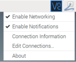
After the installation is completed, you will see the NetworkManager icon in the status bar of the system desktop.
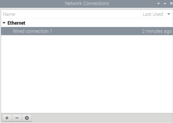
Right-click the NetworkManager icon and select Edit Connections.

Select the connection name to modify, and then click the gear below.

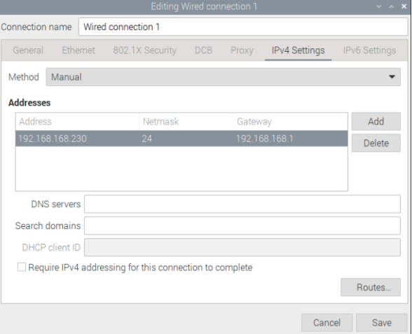
Switch to the configuration page of IPv4 Settings. If you want to set static IP, the Method selects Manual, and Addresses the IP you want to configure. If you want to set it as dynamic IP acquisition, just configure the Method as Automatic(DHCP) and restart the device.

If you use the Lite version of the system, you can configure it through the command line.
If you want to use the command to set the static IP for the device, you can refer to the following methods.
Set the static IP
sudo nmcli connection modify <name> ipv4.addresses 192.168.1.101/24 ipv4.method manual
Set the gateway
sudo nmcli connection modify <name> ipv4.gateway 192.168.1.1
Set dynamic IP acquisition
sudo nmcli connection modify <name> ipv4.method auto
4.2.3 Configuration With dhcpcd Tool
The official system of Raspberry Pi uses dhcpcd as the network management tool by default.
If you use the factory image provided by us and want to switch from NetworkManager to dhcpcd network management tool, you need to stop and disable NetworkManager service and enable dhcpcd service first.
sudo systemctl stop NetworkManager
sudo systemctl disable NetworkManager
sudo systemctl enable dhcpcd
sudo reboot
The dhcpcd tool can be used after the system is restarted.
Static IP can be set by modifying/etc/dhcpcd.conf. For example, eth0 can be set, and users can set wlan0 and other network interfaces according to their different needs.
interface eth0
static ip_address=192.168.0.10/24
static routers=192.168.0.1
static domain_name_servers=192.168.0.1 8.8.8.8 fd51:42f8:caae:d92e::1
4.3 WiFi (optional)
Customers can purchase ED-IPC2000 series with WiFi version, which supports 2.4 GHz and 5.0 GHz IEEE 802.11 b/g/n/ac dual-band WiFi. We provide dual-band external antenna, which has passed wireless authentication together with Raspberry Pi CM4.
4.3.1 Enable WiFi
The WiFi function is blocked by default, so you need to set the country region before you can use it. If you use the desktop version of the system, please refer to the chapter: Initialization Settings Configure WiFi. If you use the Lite version of the system, please use raspi-config to set the WiFi country area. Please refer to the documentation.:"Raspberry Pi official documents - Using the Command Line"
4.3.1.1 Configure Using The Network Manager Tool
After installing the desktop plug-in, you can directly connect to the WIFI network through the desktop icon.
You can also use the command line to execute the following commands:
Scan WIFI
sudo nmcli device wifi
Connect WIFI with password
sudo nmcli device wifi connect <SSID> password <password>
Set up WIFI automatic connection
sudo nmcli connection modify <name> connection.autoconnect yes
4.3.1.2 Configure Using The dhcpcd Tool
The official system of Raspberry Pi uses dhcpcd as the network management tool by default.
sudo raspi-config
- Choose 1 System Options
- Choose S1 Wireless LAN
- Choose your country in Select the country in which the Pi is to be used ,than choose OK,This prompt only appears when setting up WIFI for the first time.
- Please enter SSID,input WIFI SSID
- Please enter passphrase. Leave it empty if none,input password than restart the device
4.3.2 External Antenna and Internal PCB Antenna
You can switch whether to use an external antenna or a built-in PCB antenna through software configuration. Considering compatibility and widest support, the factory default system is the built-in PCB antenna. If the customer chooses a complete machine with a case and equipped with an external antenna, you can switch by the following operations:
Edit /boot/config.txt
sudo nano /boot/config.txt
Choose external antenna add
dtparam=ant2
Then reboot the device.
4.3.3 AP and Bridge Mode
WiFi on ED-IPC2000 series also supports configuration in AP router mode, bridge mode or mixed mode.
Please refer to the open source project github: garywill/linux-router to learn how to configure it.
4.4 Bluetooth (optional)
ED-IPC2000 series can be selected whether the Bluetooth function is integrated or not. If it is equipped with Bluetooth, this function is turned on by default.
Bluetoothctl can be used to scan, pair and connect Bluetooth devices. Please refer to the ArchLinux-Wiki-Bluetooth guide to configure and use Bluetooth.
4.4.1 Usage
Scan:
bluetoothctl scan on/off
Find:
bluetoothctl discoverable on/off
Trust device:
bluetoothctl trust [MAC]
Connect device:
bluetoothctl connect [MAC]
Disconnect device:
bluetoothctl disconnect [MAC]
4.4.2 Example
Into bluetootch shell
sudo bluetoothctl
Enable Bluetooth
power on
Scan device
scan on

Discovery started
[CHG] Controller B8:27:EB:85:04:8B Discovering: yes
[NEW] Device 4A:39:CF:30:B3:11 4A-39-CF-30-B3-11
Find the name of the turned-on Bluetooth device, where the name of the turned-on Bluetooth device is test.
devices

Device 6A:7F:60:69:8B:79 6A-7F-60-69-8B-79
Device 67:64:5A:A3:2C:A2 67-64-5A-A3-2C-A2
Device 56:6A:59:B0:1C:D1 Lefun
Device 34:12:F9:91:FF:68 test
Pair device
pair 34:12:F9:91:FF:68
Attempting to pair with 34:12:F9:91:FF:68
[CHG] Device 34:12:F9:91:FF:68 ServicesResolved: yes
[CHG] Device 34:12:F9:91:FF:68 Paired: yes
Pairing successful
Add as trusted device
trust 34:12:F9:91:FF:68
[CHG] Device 34:12:F9:91:FF:68 Trusted: yes
Changing 34:12:F9:91:FF:68 trust succeeded
4.5 RTC
ED-IPC2000 series are integrated with RTC. For the version sold in China, we will install CR1220 button cell (RTC backup power supply) by default when shipping. In this way, the system can be guaranteed to have an uninterrupted and reliable clock, which is not affected by factors such as equipment power down.
The default shipping system image will integrate the RTC automatic synchronization service we wrote, so guests can automatically synchronize the clock without setting it, and can use RTC without feeling. The general principle is:
When the system is turned on, the service automatically reads the saved time from RTC and synchronizes it to the system time.
If there is an Internet connection, the system will automatically synchronize the time from the NTP server and update the local system time with Internet time.
When the system is shut down, the service automatically writes the system time into RTC and updates the RTC time.
Because of the installation of button cell, although CM4 Sensing is powered off, RTC is still working and timing.
In this way, we can ensure that our time is accurate and reliable.
WARNING
If it is the first time to boot, because there is no effective time in RTC, synchronization may fail, so just restart it directly. When rebooting, the system time will be written into RTC for normal use.
If you don't want to use this service, you can turn it off manually:
sudo systemctl disable rtc
sudo reboot
Re-enable this service:
sudo systemctl enable rtc
sudo reboot
Read RTC manually:
sudo hwclock -r2022-11-09 07:07:30.478488+00:00
Manually synchronize RTC time to the system:
sudo hwclock -s
Write the system time into RTC
sudo hwclock -w
Trouble Shooting
Please first check whether there is an rtc device (/dev/rtc0) mount:
ls /dev/rtc0
if not, maybe you used the official standard system, but didn't install our BSP package. Please refer to the chapter Install BSP Online Based On The Original Raspberry Pi OS. In addition, you also need to install ed-rtc package to enable RTC automatic synchronization.
Other possible checkpoints:
- l Is CR1220 button cell installed?
- l NTP network time protocol, you need to connect to the Internet to synchronize the time automatically, and you need to open the port (UDP, 123), otherwise the synchronization will fail.
4.6 LED Indicatior
ED-IPC2000 series have two indicators, the red LED is connected with the LED_PI_nPWR pin of CM4, which is the power indicator light, and the green LED is connected with the LED_PI_nACTIVITY pin of CM4, which is the running status indicator light.
4.7 Buzzer
The buzzer is controlled by GPIO6.
Open buzzer:
raspi-gpio set 6 op dh
Close buzzer
raspi-gpio set 6 op dl
4.8 Encryption Chip
Install atecc tool: atecc-util
For more encryption chip usage, please refer to the README document in the link.
4.9 Camera (optional)
If the device is equipped with a camera, you can use the command:
Check camera
libcamera-hello
Camera shots
libcamera-jpeg -o test.jpg
Record 10 seconds of video
libcamera-vid -t 10000 -o test.h264
Play the video you just recorded
vlc test.h264
TIP
Only ED-IPC2020 includes this interface
4.10 Audio (optional)
TIP
Only ED-IPC2020 includes this interface.
4.10.1 Check Sound Card
Users can use the following commands to view sound card devices:
aplay -l
4.10.2 Recording
Users can record with the following commands:
arecord -fcd test.mp3
It also supports users to specify sound card devices for recording:
arecord -fcd -Dhw:<sound card number> test.mp3
For more usage of arecord, users can view it with the following commands:
man arecord
4.10.3 Playback
Users can use the following commands to play sounds:
aplay test.mp3
It also supports users to specify sound card devices for recording:
aplay -Dhw:<sound card number> test.mp3
For more usage of aplay, users can check it with the following command:
man aplay
4.11 Serial Communication
4.11. 1 Install picocom Tool
Picocom serial terminal can be debugged conveniently in Linux environment.
First install picocom
sudo apt-get install picocom
You can type Ctrl+a first, and then Ctrl+h to see the available commands.
*** Picocom commands (all prefixed by [C-a])

*** [C-x] : Exit picocom
*** [C-q] : Exit without reseting serial port
*** [C-b] : Set baudrate
*** [C-u] : Increase baudrate (baud-up)
*** [C-d] : Decrease baudrate (baud-down)
*** [C-i] : Change number of databits
*** [C-j] : Change number of stopbits
*** [C-f] : Change flow-control mode
*** [C-y] : Change parity mode
*** [C-p] : Pulse DTR
*** [C-t] : Toggle DTR
*** [C-g] : Toggle RTS
*** [C-|] : Send break
*** [C-c] : Toggle local echo
*** [C-w] : Write hex
*** [C-s] : Send file
*** [C-r] : Receive file
*** [C-v] : Show port settings
*** [C-h] : Show this message
Type Ctrl+a first, then Ctrl+c to switch the local echo mode.
Type Ctrl+a first, then Ctrl+q to exit picocom.
4.11.2 Debug UART

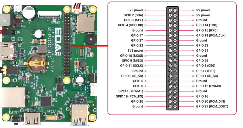
There is a debugging serial port in ED-IPC2000 series 40Pin, and GPIO14 GPIO15 are read and write pins respectively.
In addition, users need to use the raspi-config tool to set it to.
- Open raspi-config: sudo raspi-config.
- Choose option 3 - Interface Options.
- Choose option P6 - Serial Port.
- Prompt Would you like a login shell to be accessible over serial? 回答 'Yes'
- Exit raspi-config
- Restart device: sudo reboot
To enable debugging serial port, you need to modify the config.txt configuration file.
sudo nano /boot/config.txt
Add at the end
[all]enable_uart=1
The default baud rate of debugging serial port is 115200. You can check the current baud rate of debugging serial port through cmdline.txt file.
sudo nano /boot/cmdline.tx
4.12 Error Message
| Error Message | explanation |
|---|---|
| GPIO-x occupied | GPIOx is occupied, please confirm whether there is a GPIO conflict. |
| Reuse i2c:x failed | The i2c pin has been used, so the corresponding pin cannot be reused as I2C. |
| Unable to reuse i2c x – addr x | The I2C address has been occupied, and the device can no longer be set to the X address. |
| Not found i2c x | /dev/i2c-x cannot be found. The I2C function may not be turned on or the I2C pin is occupied and cannot be set to I2C. |
| Uart x cannot reuse | Uart x cannot be reused, and the pin may have been occupied. |
| GPIO x has already been configured | GPIO x has already been configured, so GPIO x can no longer be configured. |
| i2c-y 0x{:x} not exist | The specified device with address x mounted on I2c-y bus does not exist. Please check whether the device exists. |
| Not found x.dtbo file | This problem is that the dtbo file is missing. If you find this problem, please contact our after-sales colleagues. |
| x not contain uuid information | This problem is that the configuration information is lost and the automatic configuration of BSP cannot be completed. If you find this problem, please contact our after-sales colleagues. |
| x not contain product information | This problem is that the configuration information is lost and the automatic configuration of BSP cannot be completed. If you find this problem, please contact our after-sales colleagues. |
