1 Hardware Manual
This chapter introduces the product overview, packing list, appearance, button and interface.
1.1 Overview
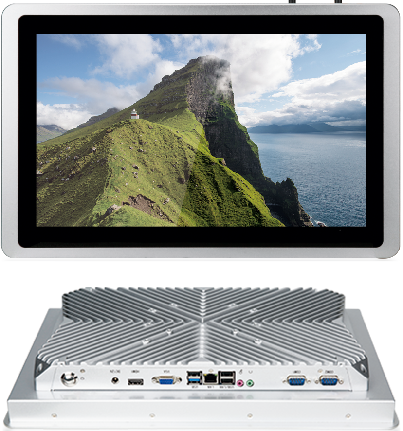
ED-HMI2320-156C is a 15.6-inch industrial HMI based on Raspberry Pi CM4. According to different application scenarios and user needs, different specifications of RAM and eMMC computer systems can be selected.
- RAM can choose 1GB, 2GB, 4GB and 8GB.
- eMMC can choose 8GB, 16GB and 32GB.
ED-HMI2630-101C provides common interfaces such as HDMI, USB, Ethernet, RS232, RS485, MIC IN and LINE OUT, and supports network access through Wi-Fi, Ethernet and 4G. It supports Micro SD Card and mSATA SSD storage expansion; integrated RTC, EEPROM and encryption chip, which enhances the ease of use and reliability of the product. It is mainly used in the field of industrial control and IOT.
1.2 Packing List
- 1 x ED-HMI2320-156c Unit
- [Optional] 1 x ED-ACC-DMB2320 (desktop installation base, with 6 M4 screws)
- [Optional Wi-Fi/BT version] 1 x 2.4GHz/5GHz Wi-Fi/BT antenna
- [Optional 4G version] 1 x 4G/LTE antenna
1.3 Appearance
Introducing the functions and definitions of interfaces on each panel.
1.3.1 Front Panel
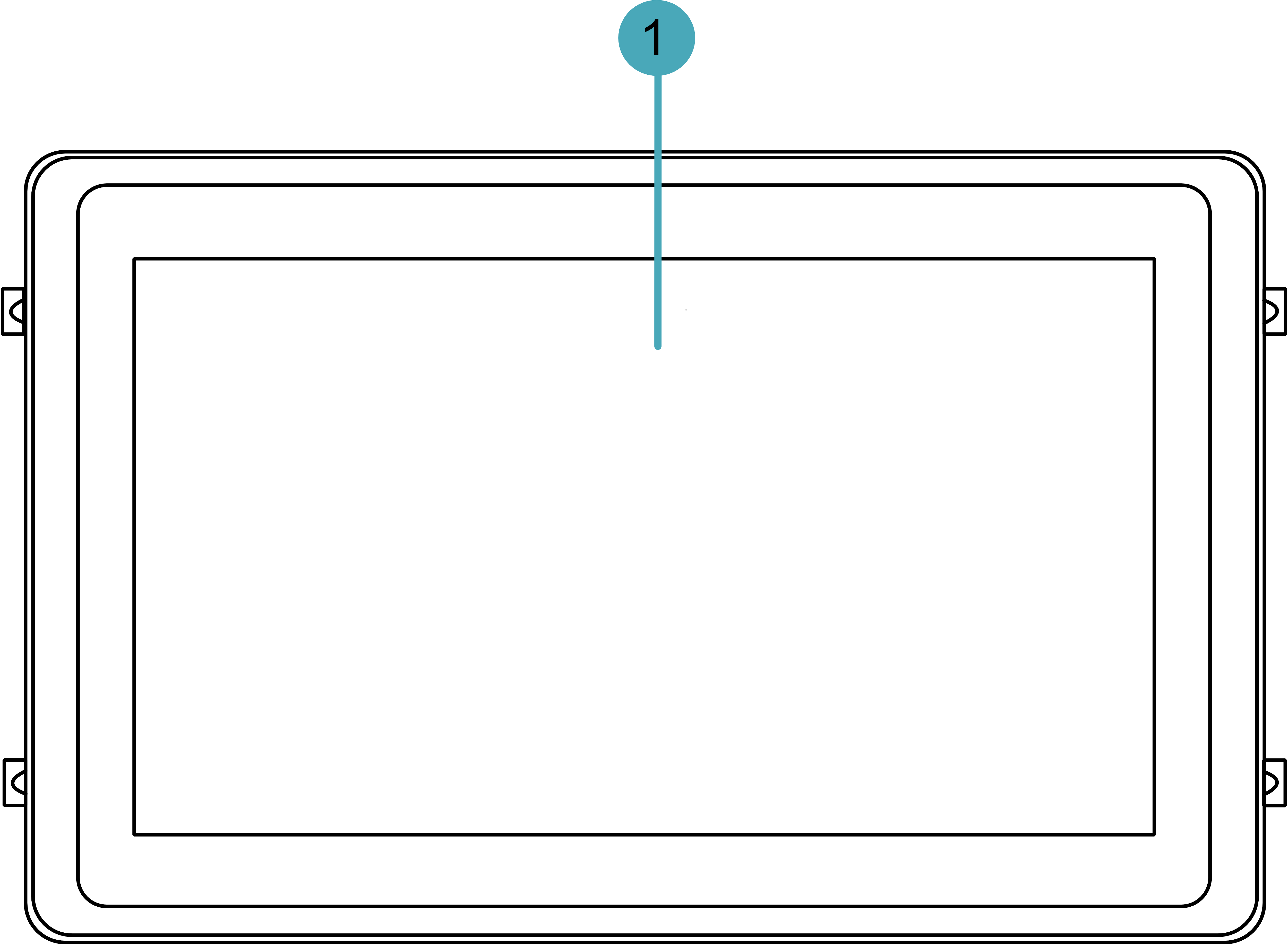
This section introduces functions and definitions of front panel.
| NO. | Function Definition |
|---|---|
| 1 | 1 x LCD display, 15.6-inch LCD touch screen, which supports up to 1920x1080 and multi-point capacitive touchscreen. |
1.3.2 Rear Panel
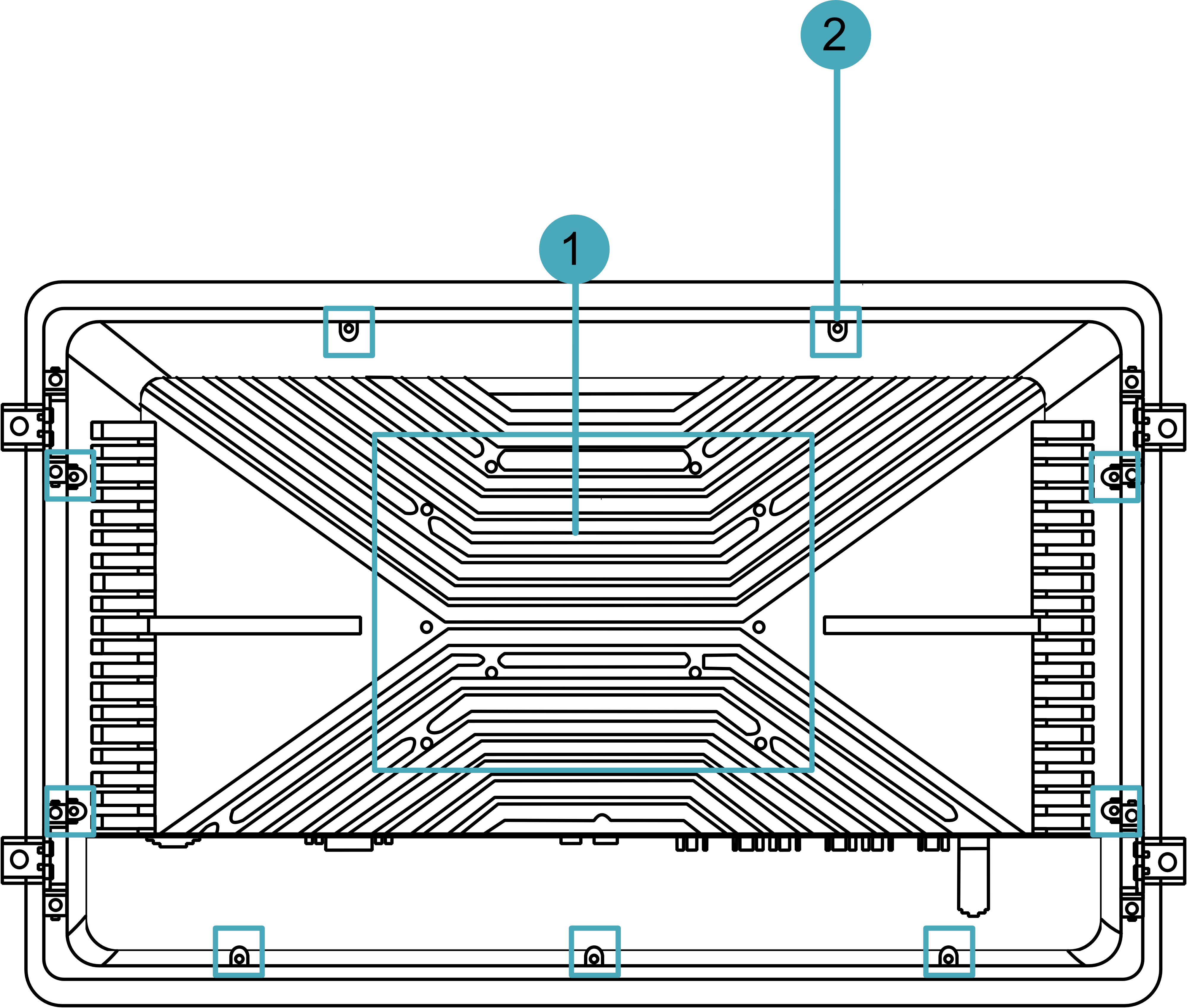
This section introduces interfaces and definitions of rear panel.
| NO. | Function Definition |
|---|---|
| 1 | 10 x base installing holes. When installing the device, it is used to install the device desktop base,. |
| 2 | 9 x Case installing holes, When closing the device case, it is used to fix the device case. |
1.3.3 Side Panel
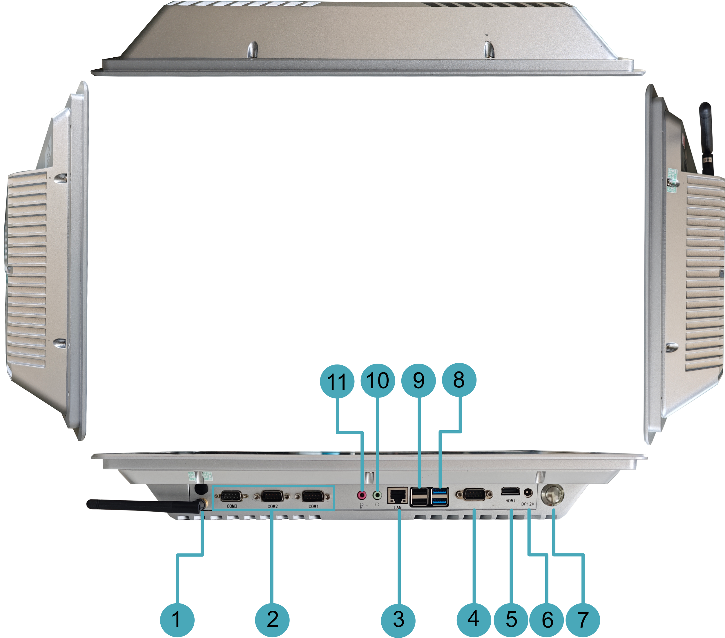
This section introduces interfaces and definitions of side panel.
| NO. | Function Definition |
|---|---|
| 1 | 2 x SMA ports for connecting 4G and Wi-Fi/BT antennas (optional). |
| 2 | 3 x RS485/232, DB9 male terminal, can be configured into different numbers of RS232 and RS485 interfaces according to actual needs. The RS232 interface uses pins 2, 3 and 5 of the terminal, and the single signal is defined as RX/TX/GND. The RS485 interface uses pins 1 and 2 of the terminal, and the single signal is defined as A/B.
|
| 3 | 1 x Ethernet interface (0/100/1000M adaptive), RJ45 terminal, for accessing Ethernet; PoE power supply can be supported through optional expansion modules, with a maximum PoE power of 60W, compatible with IEEE 802.3bt standard. |
| 4 | 1 x RS232, DB9 male terminal, using pins 2, 3 and 5 of the terminal, the corresponding signals are defined as RX/TX/GND, single-board debugging serial port, which is used for single-board debugging. |
| 5 | 1 x HDMI, type-A connector, which is compatible with HDMI 2.0 standard. Resolution supports 4K 60Hz. |
| 6 | 1 x DC input, DC Jack connector (optional 2-Pin 3.5mm pitch Phoenix terminal), with overcurrent, overvoltage and reverse polarity protection, supporting 9V~36V input. |
| 7 | 1 x Power button, including short press and long press operations. When it is not powered on:
|
| 8 | 2 x USB 3.0, double-layer type-A connector, each channel supports up to 5Gbps transmission rate. |
| 9 | 2 x USB 2.0, double-layer type-A connector, each channel supports up to 480Mbps transmission rate. |
| 10 | 1 x LINE output, green 3.5mm audio interface, stereo output. |
| 11 | 1 x MIC input, red 3.5mm audio interface, supports microphone input. |
1.4 Button
The ED-HMI2320-156c device includes a button. Short press and long press correspond to different operations. When the device is not powered on, short press the button to boot the device; long press to enter the eMMC flashing mode, in which the image can be flashed to the device. when the device is powered on, short press the button is invalid, long press the button will force the device to shut down.
1.5 Interface
1.5.1 Power Supply Interface
The ED-HMI2320-156c device includes 1 power input, DC Jack connector (optional 2-pin 3.5mm pitch Phoenix terminal), supports 9V~36V input, the interface silk screen is "DC12V", and the pin definition is as follows.
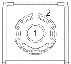 | Pin ID | Pin Name |
|---|---|---|
| 1 | 9V~36V | |
| 2 | GND |
1.5.2 HDMI Interface
The ED-HMI2320-156c device includes one HDMI interface, a standard type-A connector, and the interface silkscreen is "HDMI". It supports connecting to an HDMI display and supports up to 4Kp60 video output.
1.5.3 COM Interface (COM0)
The ED-HMI2320-156c device includes one COM0 interface with a DB9 male terminal. By default, it is the debugging serial port of the board and is used for device debugging.
Pin Definition
The terminal pins are defined as follows:
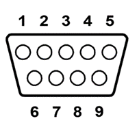 | Pin ID | Pin Name |
|---|---|---|
| 1 | NC | |
| 2 | DB9_RS232_RX | |
| 3 | DB9_RS232_TX | |
| 4 | NC | |
| 5 | GND | |
| 6~9 | NC |
The pin names of the RS232 interface corresponding to CM4 are as follows:
| Signal | CM4 GPIO Name | CM4 Pin Out |
|---|---|---|
| DB9_RS232_RX | GPIO15 | CM4_UART_RXD0 |
| DB9_RS232_TX | GPIO14 | CM4_UART_TXD0 |
1.5.4 COM Interface (COM1~COM3)
The ED-HMI2320-156c device includes 3 COM ports (COM1~COM3), which can be expanded to 0~2 RS485 ports and 1~3 RS232 ports according to actual user needs.
3 x RS232 without RS485
The pin names of CM4 corresponding to RS232 are as follows:
| COM口 | Signal | CM4 GPIO Name | CM4/SPI Pin Out |
|---|---|---|---|
| COM1 | COM1_RS232_RX | GPIO1 | CM4_UART_RXD2 |
| COM1_RS232_TX | GPIO0 | CM4_UART_TXD2 | |
| COM2 | COM2_RS232_RX | GPIO5 | CM4_UART_RXD3 |
| COM2_RS232_TX | GPIO4 | CM4_UART_TXD3 | |
| COM3 | COM3_RS232_RX | - | SPI_UART_RXD1 |
| COM3_RS232_TX | - | SPI_UART_TXD1 |
2 x RS232 and 1 x RS485
The pin names of CM4 corresponding to RS232 and Rs485 are as follows:
| COM口 | Signal | CM4 GPIO Name | CM4 Pin Out |
|---|---|---|---|
| COM1 | COM1_RS232_RX | GPIO1 | CM4_UART_RXD2 |
| COM1_RS232_TX | GPIO0 | CM4_UART_TXD2 | |
| COM2 | COM2_RS232_RX | GPIO5 | CM4_UART_RXD3 |
| COM2_RS232_TX | GPIO4 | CM4_UART_TXD3 | |
| COM3 | RS485_1_A | GPIO12 | CM4_UART5_TXD |
| RS485_1_B | GPIO13 | CM4_UART5_RXD |
1 x RS232 and 2 x RS485
The pin names of CM4 corresponding to RS232 and Rs485 are as follows:
| COM口 | Signal | CM4 GPIO Name | CM4 Pin Out |
|---|---|---|---|
| COM1 | COM1_RS232_RX | GPIO1 | CM4_UART_RXD2 |
| COM1_RS232_TX | GPIO0 | CM4_UART_TXD2 | |
| COM2 | RS485_1_A | GPIO12 | CM4_UART5_TXD |
| RS485_1_B | GPIO13 | CM4_UART5_RXD | |
| COM3 | RS485_2_A | GPIO8 | CM4_UART4_TXD |
| RS485_2_B | GPIO9 | CM4_UART4_RXD |
1.5.4.1 RS232 Interface
ED-HMI2320-156C device includes 1~3 RS232 ports, with DB9 male terminals. The RS232 interface uses pins 2, 3, and 5 of the terminal, and the single-channel signal is defined as RX/TX/GND.
RS232_1 Pin Definition
The terminal pins are defined as follows:
 | Pin ID | Pin Name |
|---|---|---|
| 1 | NC | |
| 2 | COM1_RS232_RX | |
| 3 | COM1_RS232_TX | |
| 4 | NC | |
| 5 | GND | |
| 6~9 | NC |
RS232_2 Pin Definition
The terminal pins are defined as follows:
 | Pin ID | Pin Name |
|---|---|---|
| 1 | NC | |
| 2 | COM2_RS232_RX | |
| 3 | COM2_RS232_TX | |
| 4 | NC | |
| 5 | GND | |
| 6~9 | NC |
RS232_3 Pin Definition
The terminal pins are defined as follows:
 | Pin ID | Pin Name |
|---|---|---|
| 1 | NC | |
| 2 | COM3_RS232_RX | |
| 3 | COM3_RS232_TX | |
| 4 | NC | |
| 5 | GND | |
| 6~9 | NC |
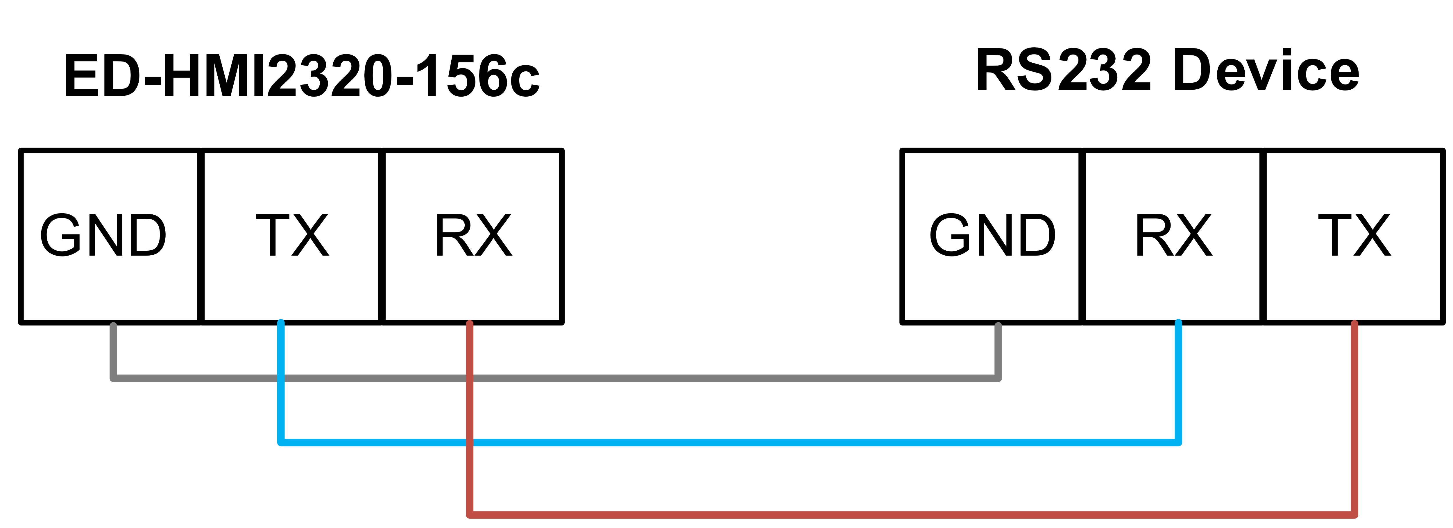
Connecting cables
The wiring diagram of the RS232 serial port is as follows:
1.5.4.2 RS485 Interface
The ED-HMI2320-156c device includes 0~2 RS485 ports with DB9 male terminal. The RS485 interface uses pins 1 and 2 of the terminal, and the single signal is defined as A/B.
RS485_1 Pin Definition
The terminal pins are defined as follows:
 | Pin ID | Pin Name |
|---|---|---|
| 1 | RS485_1_B | |
| 2 | RS485_1_A | |
| 3 | GND | |
| 4 | NC | |
| 5 | NC | |
| 6~9 | NC |
RS485_2 Pin Definition
The terminal pins are defined as follows:
 | Pin ID | Pin Name |
|---|---|---|
| 1 | RS485_2_B | |
| 2 | RS485_2_A | |
| 3 | GND | |
| 4 | NC | |
| 5 | NC | |
| 6~9 | NC |
Connecting cables
The wiring diagram of the RS485 serial port is as follows:

1.5.5 USB 3.0 Interface
The ED-HMI2320-156c device includes two USB 3.0 interfaces with double-layer standard type-A connectors. It supports connecting standard USB 3.0 peripherals and supports up to 5Gbps.
1.5.6 USB 2.0 Interface
The ED-HMI2320-156c device includes two USB 2.0 interfaces with double-layer standard type-A connectors. It supports connecting standard USB 2.0 peripherals and supports up to 480Mbps.
1.5.7 1000M Ethernet Interface (ETH0)
The ED-HMI2320-156c device includes one adaptive 10/100/1000M Ethernet interface, the interface silkscreen is "LAN", using RJ45 terminals, and can support PoE power supply when used with expansion modules. It is recommended to use a Cat6 or higher specification network cable when connected to Ethernet.
1.5.8 LINE OUT Interface
The ED-HMI2320-156c device includes 1 audio output interface, the interface silkscreen is "", uses a green 3.5mm audio connector and supports stereo output.
1.5.9 MIC IN Interface
The ED-HMI2320-156c device includes 1 MIC input interface, the interface silkscreen is " ", uses a red 3.5mm audio connector and supports microphone input.
1.5.10 Antenna interface (optional)
The ED-HMI2320-156c device includes up to 2 SMA antenna interfaces, corresponding to the 4G antenna and Wi-Fi/BT antenna.
