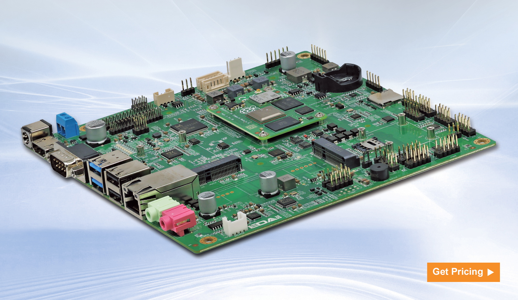
| ED-SBC2300 Series Features |
| Mini-ITX Industrial Computer Motherboard Based on Raspberry Pi CM4 |
| Mini-ITX standard motherboard, fanless design |
| Broadcom BCM2711, quad core Cortex-A72 (ARM v8) 64-bit SoC @ 1.5GHz |
| Up to 8GB LPDDR4 RAM and 32GB eMMC storage |
| Support Micro SD card and mSATA SSD storage expansion |
| Support HDMI+LVDS or HDMI+eDP touchscreen dual displays |
| LAN supports up to 1Gbps (dual Lans are optional) |
| Support 2 x USB 3.0 and 5 x USB 2.0 |
| Support 2 x RS485 and 7x RS232 |
| 2.4GHz and 5GHz dual-band Wi-Fi, Bluetooth and 4G LTE |
| Wide voltage power input range of DC 9V~36V and PoE power supply |
| Integrated RTC, EEPROM and crypto authentication |
Document Download
| ED-SBC2300 Datasheet |
Specifications
| System | |
| CPU | Broadcom BCM2711, quad core Cortex-A72 (ARM v8) 64-bit SoC @ 1.5GHz |
| VPU |
H.265(HEVC), up to 4Kp60 decode H.264, up to 1080p60 decode, 1080p30 encode |
| GPU | OpenGL ES 3.1 & Vulkan 1.0 |
| Memory | Options for 1GB, 2GB, 4GB, 8GB LPDDR4-3200 SDRAM |
| Storage |
Options for 8GB, 16GB, 32GB eMMC storage Micro SD card (user storage expansion) mSATA SSD (optional) |
| Software | |
| Operating System |
Raspberry Pi OS(Desktop) 32-bit
Raspberry Pi OS(Lite) 32-bit
Raspberry Pi OS(Desktop) 64-bit
Raspberry Pi OS(Lite) 64-bit
|
| Rear I/O | |
| Power | 1 x DC IN, DC Jack connector, with reverse polarity protection, overvoltage protection, and overcurrent protection. It supports 9V~36V input. |
| HDMI | 1 x HDMI port, type A connector, which compatibles with HDMI 2.1 standard and supports 4K 60Hz. |
| COM | 1 x RS232 port, DB9 male connector, using the 2, 3 and 5 pins, the corresponding signal is defined as RX/TX/GND. |
| USB 3.0 | 2 x USB 3.0 ports, type A connector, support up to 5Gbps. |
| USB2.0 / 1000M Ethernet |
Choose one between 2 x USB 2.0 ports and 1 x 1000M Ethernet port. - 2 x USB 2.0 ports, type A connector, which support up to 480Mbps. - 1 x adaptive 10/100/1000M ethernet port, RJ45 connector. It can be used to access the network. Different ports can be selected according to actual application. - ED-SBC2310: 2 x USB 2.0 - ED-SBC2311: 1 x 1000M Ethernet - ED-SBC2320: 2 x USB 2.0 - ED-SBC2321: 1 x 1000M Ethernet |
| 1000M Ethernet | 1 x adaptive 10/100/1000M ethernet port, RJ45 connector. It can be used to access the network. PoE can be supported through optional expansion module. The maximum power of PoE is 60W and it is compatible with IEEE 802.3bt standard. |
| LINE OUT (optional) |
1 x Audio Output, 3.5mm audio jack connector(green), stereo audio output. Note: Only ED-SBC2320 and ED-SBC2321 contains this interface. |
| MIC IN (optional) |
1 x MIC Input, 3.5mm audio jack connector(red), which can connect to microphone. Note: Only ED-SBC2320 and ED-SBC2321 contains this interface. |
| SD Card Slot | 1 x Micro SD card slot, which is used to install SD card for storing user data. |
| SIM Card Slot | 1 x Micro SIM card slot, which is used to install SIM card for getting 4G signal. |
| Expansion I/O | |
| Power Supply |
1 x power port, 2-Pin 5mm spacing connector, reserving to provide power supply for motherboard. It supports 9V~36V input, the signal is defined as VIN+/GND.
|
| Speaker (optional) |
1 x PA output, 4-Pin 2.0mm spacing WTB connector, dual channel stereo audio output. It can be extended to connect two 4Ω 3W stereo speakers, these pins are defined as R+/R-/L+/L-. Note: Only ED-SBC2320 and ED-SBC2321 contains this interface. |
| USB 2.0 |
3 x USB 2.0 ports or 5 x USB 2.0 ports, different numbers of USB 2.0 ports can be selected according to actual application. - ED-SBC2310 and ED-SBC2320: 3 x USB 2.0 ports (include USB1 and USB3) - ED-SBC2311 and ED-SBC2321: 5 x USB 2.0 ports (include USB1, USB2 and USB3) USB1, USB2 and USB3 are the silkscreens of the USB 2.0 ports on the motherboard, corresponding to J19, J20 and J21. The ports and functions are defined as follows: - USB1 and USB2 respectively contain 2 x USB 2.0 ports, 2x5(9)-Pin 2.54mm spacing Pin Header. These pins are defined as +5V/+5V/USB1 Date-/USB2 Date-/USB1Date+/ USB2Date+/GND/GND/NC. - USB3 contains 1 x USB 2.0 port, 5-Pin 2.54mm spacing Pin Header, these pins are defined as +5V/Date-/Date+/GND/NC. Note: Only support to choose one between USB2 and double-layer type A USB2.0 ports. |
| RS232 | 6 x RS232, 2x5(9)-Pin 2.54mm spacing Pin Header, which support to expand the RS232 ports. The single signal is defined as DCD/RXD/TXD/DTR/GND/DSR/RTS/CTS/R1. |
| * 1RS485 | 2 x RS485, 2x2-Pin 2.54mm spacing Pin Header, which support to expand the RS485 port and the single signal is defined as A/B. A 120R jumper resistor is reserved between A and B of RS485 line. The jumper cap can be inserted to enable the jumper resistor. |
| 6-Pin GPIO | 1 x GPIO Pin Header, 2x3-Pin 2.54mm spacing Pin Header, which uses to lead out the expansion GPIO ports. User can customize the function according to actual application. The pins are defined as VCC/GND/4xGPIO. |
| mSATA | 1 x mSATA port, Mini PCIe connector, which supports to connect mSATA* 2 SSD. |
| Front Panel (Buttons/ Indicators) | 1 x Front Panel port, 2x5-Pin 2.54mm spacing Pin Header, reserving to connect power button, reset button, HDD indicator and power indicator. The pins are defined as HDD LED+/HDD LED-/PWR LED+/PWR LED-/RESET-SW/ GND/GND/POWER-SW/GND/NC. |
| Auto-boot after powering on |
1 x Auto-boot port, 3-Pin 2.54mm spacing Pin Header, which can set whether to enable the auto-boot after powering on by choosing to connect different pins. The pins and functions are defined as follows: - Pin 1-2(Default): Disable - Pin 2-3: Enable |
| LVDS Display (optional) |
1 x LVDS Display Port, 2x15-Pin 2.54mm spacing Pin Header. It is reserved to connect LVDS display, and supports up to 1080p 60Hz. Note: Only ED-SBC2320 and ED-SBC2321 contains this interface. The LVDS and eDP interfaces can not be selected at the same time, you can only select LVDS or eDP. |
| eDP Display (optional) |
1 x eDP Display Port, 2x15-Pin 2.54mm spacing Pin Header. It is reserved to connect eDP display, and supports up to 1080p 60Hz. Note: Only ED-SBC2320 and ED-SBC2321 contains this interface. The LVDS and eDP interfaces can not be selected at the same time, you can only select LVDS or eDP. |
| Voltage Setting of LVDS/eDP Display (optional) |
1 x Voltage Setting port of LVDS/eDP display, 2x15-Pin 2.54mm spacing Pin Header. We can set different voltage by choosing to connect different pins, which meets the power supply requirements of various LVDS/eDP display. The pins and functions are defined as follows: - Pin 1-2(Default): +3.3V - Pin 3-4: +5V - Pin 5-6: +12V Note: Only ED-SBC2320 and ED-SBC2321 contains this interface. |
| Enabling Setting of LVDS/eDP Display (optional) |
1 x Enabling Setting port of LVDS/eDP display, 2x15-Pin 2.54mm spacing Pin Header. We can open or close the LVDS/eDP display by choosing to connect different pins. The pins and functions are defined as follows: - Pin 1-2: Open LVDS/eDP display - Pin 2-3(Default): Close LVDS/eDP display Note: Only ED-SBC2320 and ED-SBC2321 contains this interface. |
| Resolution Setting of LVDS Output (optional) |
1 x Resolution Setting port of LVDS Output, 3x4-Pin 2.0mm spacing Pin Header. We can select screens of different sizes and resolutions by setting the level of pins. Available screens: 12.1-inch (800x600), 15-inch (1024x768), 15.6-inch (1920x1080), 17-inch (1280x1024) and 21.5-inch (1920x1080). Note: Only ED-SBC2320 and ED-SBC2321 contains this interface. |
| Brightness Control of LVDS/eDP Display (optional) |
1 x Brightness Control port of LVDS/eDP display, 4-Pin 2.0mm spacing WTB connector. We can adjust brightness of LVDS/eDP display by choosing to connect different pins. The pins and functions are defined as follows: - Pin 1-2:Brightness increase - Pin 2-3:Brightness decrease - Pin 2-4:Brightness enable/disable Note: Only ED-SBC2320 and ED-SBC2321 contains this interface. |
| Backlight Control (optional) |
1 x Backlight Control port, 6-Pin 2.0mm spacing WTB connector, which provides 12V power supply, PWM enable and PWM adjustment for backlight of LVDS/eDP display. The pins are defined as +12V/+12V/GND/GND/LVDS_BKL_EN/LVDS_BKL_CTRL. Note: Only ED-SBC2320 and ED-SBC2321 contains this interface. |
| Backlight Driver (optional) |
1 x Backlight Driver port, 6-Pin 2.0mm spacing WTB connector, which integrates on-board backlight driver circuit, supports enabling and adjustment of backlight brightness. The pins are defined as Vdc-/Vdc-/Vdc+/Vdc+/Vdc-/Vdc-. Note: Only ED-SBC2320 and ED-SBC2321 contains this interface. |
| Expansion Performance | |
| EEPROM |
Supports 4K byte storage and improves the ease of use of device.
|
| Crypto Authentication | It can be matched to realize the required upper layer application and improves the security of device. |
| RTC |
Ensure that the system clock is not affected by device power-off. Note: A CR2032 battery is provided by default in China. |
| Buzzer | A tip or an abnormity can be configurated according to actual application, which realizes the alarm function. |
| Electrical Characteristics | |
| Input Voltage | 9V ~ 36V DC |
| Maximum Power Consumption | 60W(Max) |
| Mechanical Characteristics | |
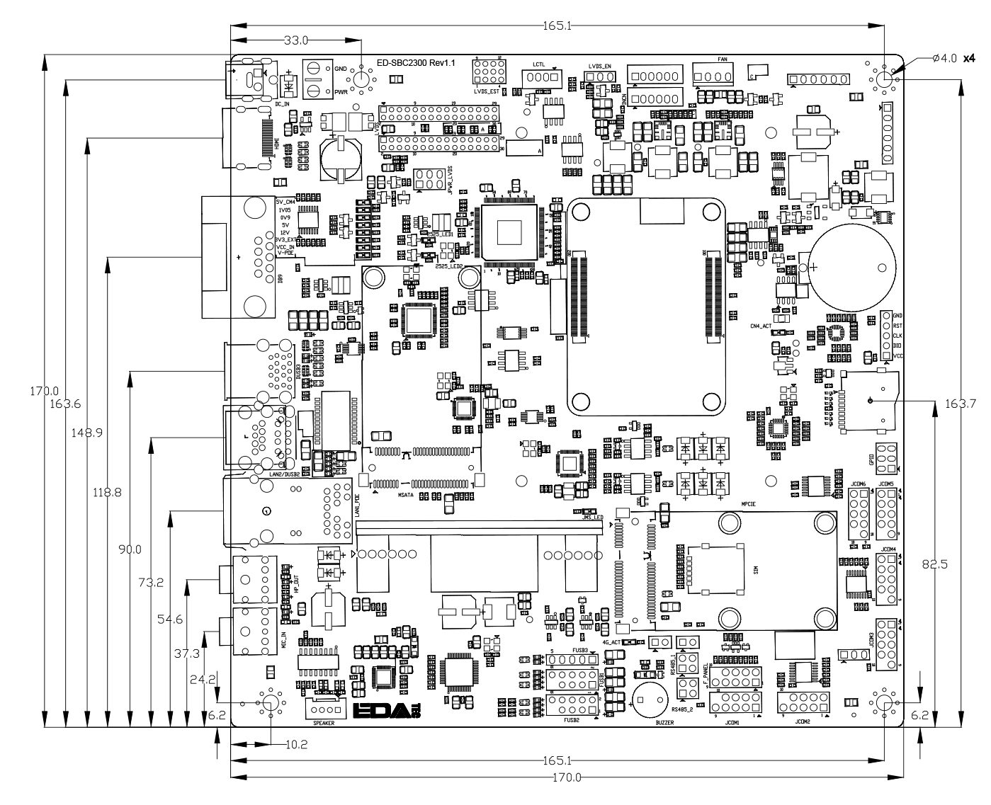
| Dimensions | 170mm x 170mm (W x D) |
| Weight | 100g |
| Wireless | |
| Wi-Fi/Bluetooth (optional) |
2.4GHz and 5GHz dual-band Wi-Fi - 2.4GHz Wi-Fi: Compatible with IEEE 802.11 b/g/n. - 5GHz Wi-Fi: Compatible with IEEE 802.11 a/n/ac. - Bluetooth 5.0, compatible with 2402MHz ~ 2480MHz frequency. |
| 4G (optional) |
Connect with various 4G LTE modules through the Mini PCIe interface. EC20-CN Module (China/India) - LTE FDD: B1/B3 - LTE TDD: B38/B39/B40/B41 - TDSCDMA: B34/B39 - WCDMA: B1 - CDMA 1x/EVDO: BC0 - GSM: 900/1800MH EC25-AFX Module (North America) - LTE-FDD: B2/B4/B5/B12/B13/B14/B66/B71 - LTE-TDD - WCDMA: B2/B4/B5 - GSM/EDGE EC25-AUX Module (Latin America/Australia/New Zealand) - LTE-FDD: B1/B2/B3/B4/B5/B7/B8/B28 - LTE-TDD: B40 - WCDMA: B1/B2/B4/B5/B8 - GSM/EDGE: B2/B3/B5/B8 EC25-EUX Module (Europe/Middle East/Africa/Thailand) - LTE-FDD: B1/B3/B7/B8/B20/B28A - LTE-TDD: B38/B40/B41 - WCDMA: B1/B8 - GSM/EDGE: B3/B8 |
| Environmental & Regulatory | |
| Operating Temperature | -25°C ~ 50°C |
| Storage Temperature | -25°C ~ 60°C |
| Ambient Humidity | 5% ~ 95% (non-condensing) |
| Certifications |
FCC
- FCC 47 CFR Part 15 Subpart B
CE
- EN IEC 62368-1/EN IEC 62311/EN IEC 61000-3-2/EN IEC 61000-3-3
- EN 55032/EN 55035/
- EN 301 489-1/EN 301 489-3/EN 301 489-17/EN 301 489-52
- EN 301 328/EN 301 440/EN 301 511/EN 301 908-1/EN 301 908-2
|
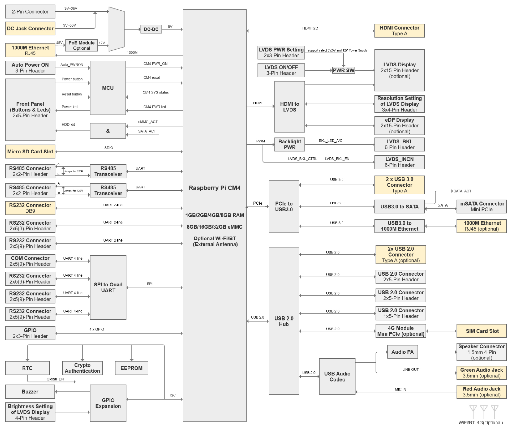
System Block Diagram
Dimension Unit:mm
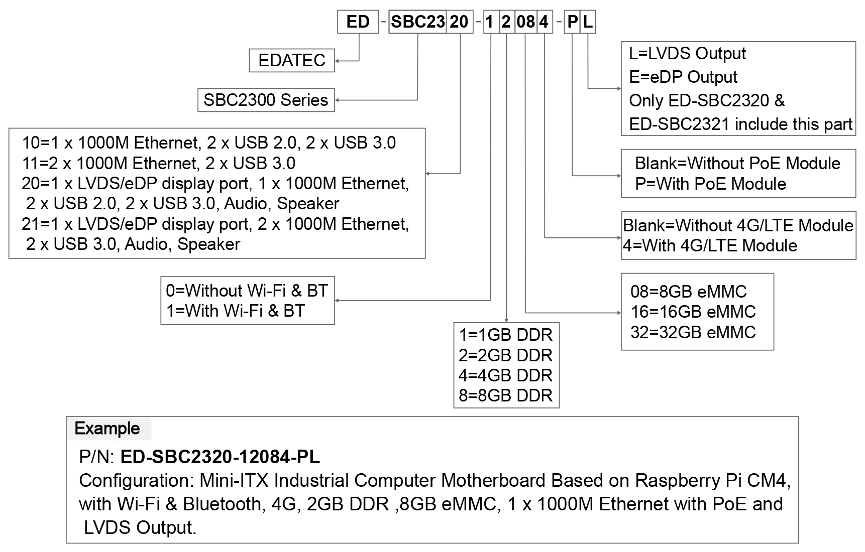
Oder Information
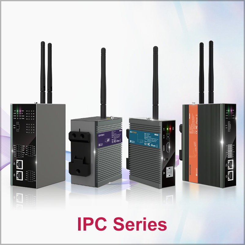
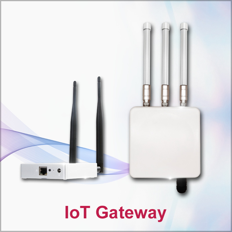
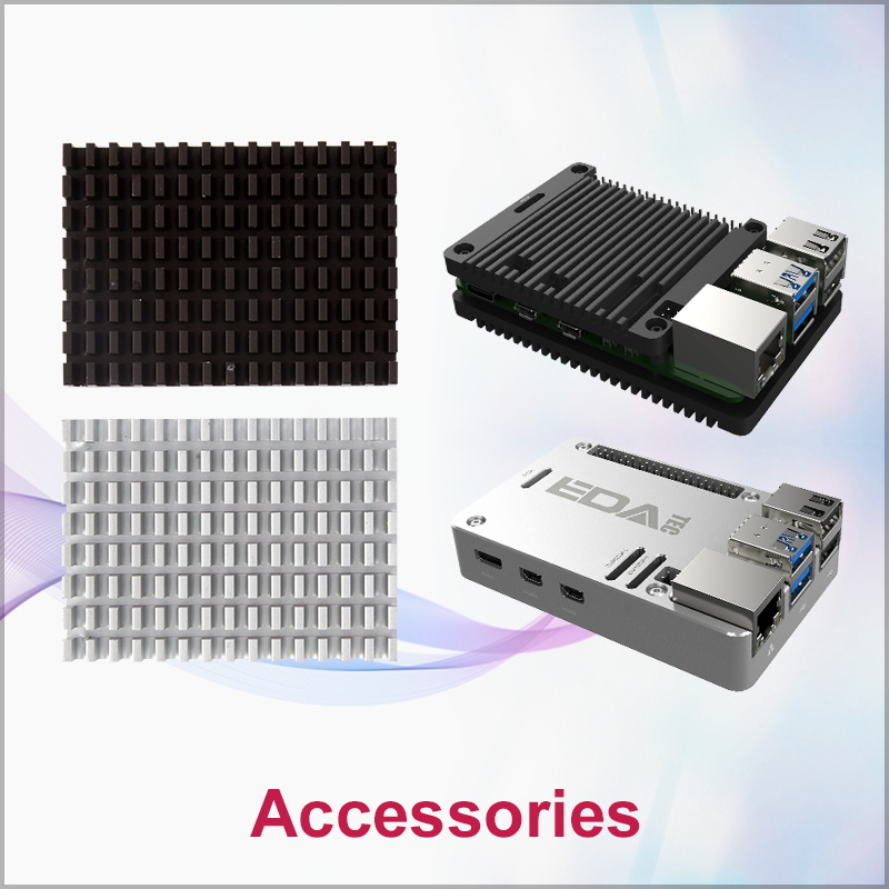
Related Products